SIROCO ARIZONA LN S User manual
Installation guide
FM 0120 E 4
26/07/10
Rev.
B
Page 1 of 6
ARIZONA LN S
1 - Device description
2 - Operation
3 - Mounting information
- Trouble shooting
5 - Security advice
SIRO O S.A.S.
10 rue Jean Rostand - Z.I.
BP 315
69745 GENAS edex
Tel: +33 (0)4 78 90 96 96
Fax: +33 (0)4 78 90 15 98
www.siroco.fr
Installation guide
FM 0120 E 4
26/07/10
Rev.
B
SIRO O S.A.S.
10 rue Jean Rostand - Z.I.
BP 135
69745 GENAS edex
Tel: +33 (0)4 78 90 96 96
Fax: +33 (0)4 78 90 15 98
www.siroco.fr
Page 2 of 6
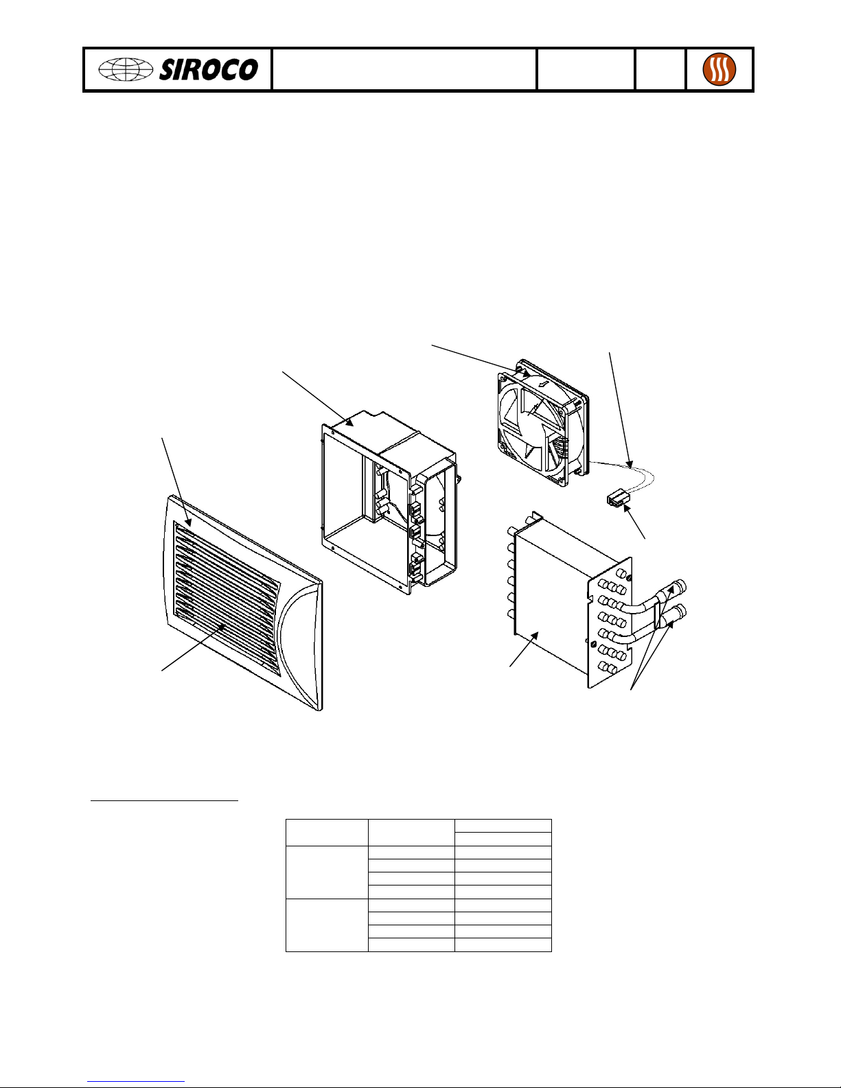
1 - Device description
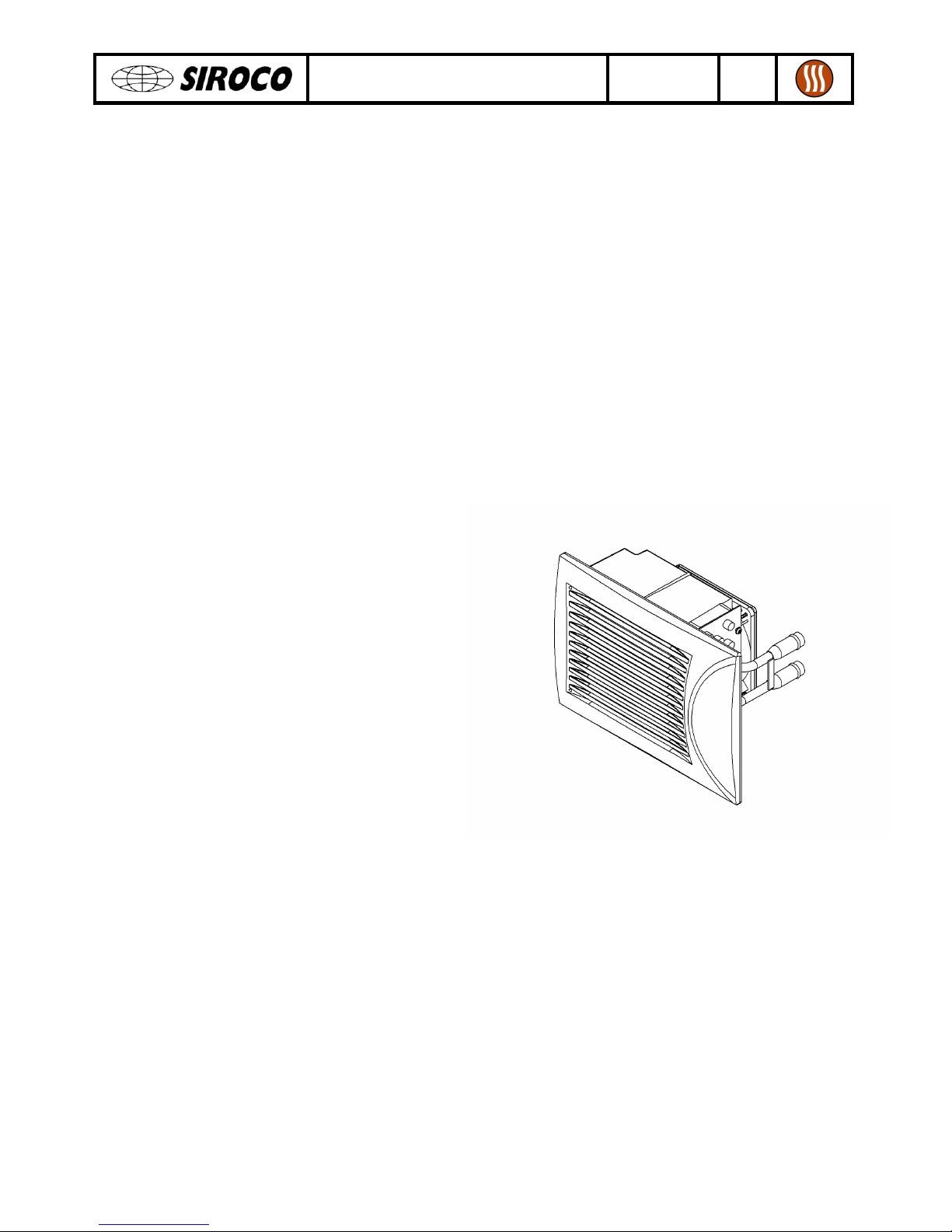
ARIZONA LN S heater consist of a blower, a coil, a plastic part and a removable front plate. Plastic
part is made from polypropylene. Front plate is made from heat and impact resistant ABS. Heater
operate under one speed: a double poles connector have to be connected. There are an input air
supply (on heater back), an output air supply (on front plate) and an input-output cooling water
supply.
ARIZONA LN S front plate is available in different colors : white, grey, anthracite or black. Heater is
available in 12 V or 24 V with connections pipes diameters of 16 mm.
Product part numbers:
ARIZONA LN S
Voltage Front plate
color Part number
White
0120 0351
Grey
0120 0352
Anthracite
0120 0353
12 V
Black
0120 0354
White
0120 0355
Grey
0120 0356
Anthracite
0120 0357
24 V
Black
0120 0358
Blower
Air outlet
Heat exchanger
P
olypropylene
plastic part
Electrical wires
(cross-section 1,5 mm
2
)
Water input and
output
Double poles
connector
ABS front plate
(supplied sectional)

Installation guide
FM 0120 E 4
26/07/10
Rev.
B
SIRO O S.A.S.
10 rue Jean Rostand - Z.I.
BP 135
69745 GENAS edex
Tel: +33 (0)4 78 90 96 96
Fax: +33 (0)4 78 90 15 98
www.siroco.fr
Page 3 of 6
2 - Operation
ooling water, beforehand heated by the vehicle, run on coil. In the same time, fan unit blows fresh
air through the heat exchanger. Then, air temperature rise up. Finally, air output evacuate hot air.
Operating conditions:
Product must be on a ventilated place.
Operating temperature have to be between -30° and +80° .
ooling fluid must be antifreeze and anticorrosive for copper and aluminum. Use a cooling fluid
officially recognize by automotive manufacturers.
Technical data:
Voltage Electrical power
Weight
Nominal air flow
Heating capacity
Sound level
12/24 V
12 W 1,4 kg 110 m³/h 3 kW 50 dB
Optimum heating capacity is reached with air inlet temperature of 0° , nominal air flow of 0,5 m
3
/h, free ethylene glycol
water and water inlet temperature of 100° .
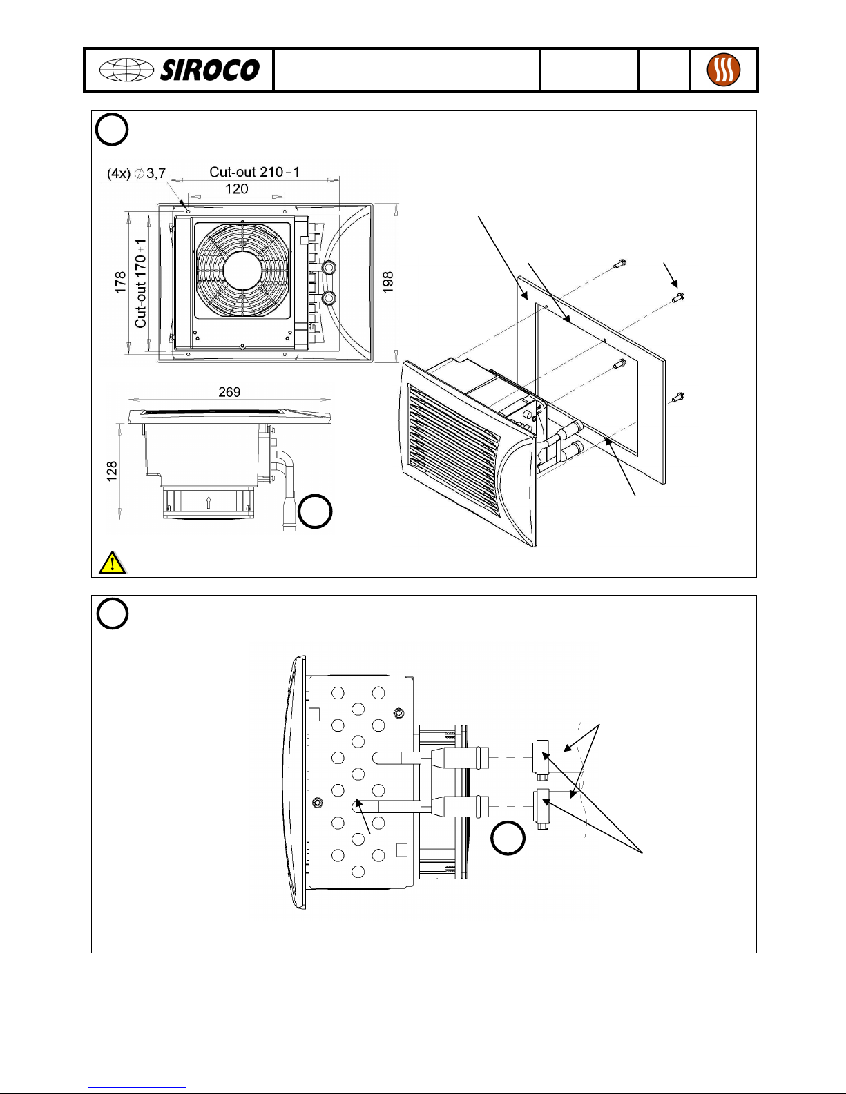
3 - Mounting information
Fix front plate on heater by using 4 supplied srews (3x15mm).
Front plate
1
4
screws
3x15 mm
ARIZONA
LN S
heater
8 x ø 3,5 mm
Installation guide
FM 0120 E 4
26/07/10
Rev.
B
SIRO O S.A.S.
10 rue Jean Rostand - Z.I.
BP 135
69745 GENAS edex
Tel: +33 (0)4 78 90 96 96
Fax: +33 (0)4 78 90 15 98
www.siroco.fr
Page 4 of 6
Fix product on its cut stand with 4 not supplied screws. Blower motor axis should rather be
in horizontal position on the vehicle.
Do not drill heater’s body so as not to damage heat exchanger !
onnect water input and output by using cooling pipes with corresponding diameter. Use
suitable clamping rings. There is no preferential cooling water direction.
heck for leaks in water.
Fixation stand
2
3
210 x 170 mm
cut-out
4
not supplied
screws
4 x Ø 3,7 mm
lamp
ing
rings
Pipes
3
3
Installation guide
FM 0120 E 4
26/07/10
Rev.
B
SIRO O S.A.S.
10 rue Jean Rostand - Z.I.
BP 135
69745 GENAS edex
Tel: +33 (0)4 78 90 96 96
Fax: +33 (0)4 78 90 15 98
www.siroco.fr
Page 5 of 6
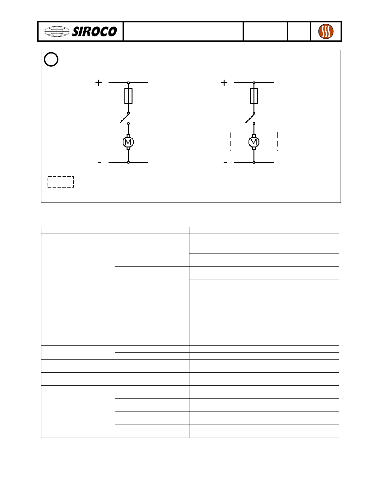
onnect double poles connector according to the following circuit diagram. Use at least 1,5
mm² cable cross-section.
Heater
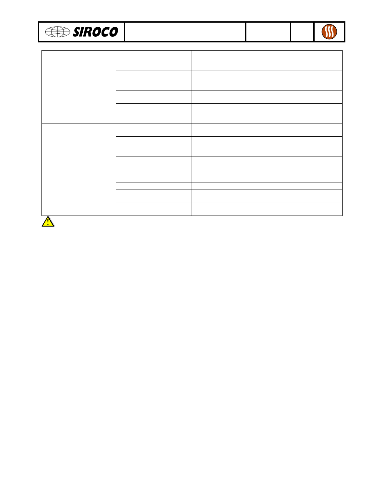
- Trouble shooting
Fault found Possible cause Action to take
heck fuse position and amperage. If necessary
replace it. Before renew a fuse, always identify
causes.
Fuse defective
Examine blowers for a blockage or another type of
defect and rectify the cause.
Switch on ignition and/or main battery switch.
heck battery connections.
No vehicle power
heck vehicle operating instructions for possible
advice.
onnecting cable
damaged or torn out
Replace cable. heck for correct cable routing and
connections according to the circuit diagram.
Electrical connections
reversed
heck connecting wires according to the circuit
diagram and if necessary assemble correctly.
Blower switch defective Replace the switch with a new original component.
Blockage in fan unit Rectify cause of blockage, e.g. object in impeller. If
necessary order new unit.
Blower not working
Blower motor defective Replace plastic part + motor.
No blower power heck connection on blower switch. Blower doesn’t operate
at all speeds Defective resistance Replace plastic part + motor.
Blower only runs at low
and middle speed
Fuse defective Replace fuse.
Unit cannot be switched
off
Short-circuit in cable Rectify circuit diagram. If necessary, install new
cable.
Rated voltage is wrong Rated voltage of unit and on-board circuit must be
the same. Order new unit.
Air nozzles closed or
covered
Open nozzles or free up inlet/outlet openings.
Electrical wires are
underdimensioned
Install recommended cable cross-section.
Blower only operate at
reduced power
Heat exchanger severely
contaminated
arefully clean avoiding damage which can lead to
leaks. WARNING! Observe safety instructions.
12 V 2 V
Motor
Motor
2 A fuse
Black wire Black wire
Red wire
Red wire
1 A
fuse
Installation guide
FM 0120 E 4
26/07/10
Rev.
B
SIRO O S.A.S.
10 rue Jean Rostand - Z.I.
BP 135
69745 GENAS edex
Tel: +33 (0)4 78 90 96 96
Fax: +33 (0)4 78 90 15 98
www.siroco.fr
Page 6 of 6
Fault found Possible cause Action to take
Vehicle engine is not
running
Start engine.
ooling water still cold Wait until the engine reaches operating temperature
Water valve closed See the vehicle manufacturer’s operating
instructions.
Water lines kinked or
squashed
Eliminate fault by installing correctly.
Heating doesn’t function
Water pump pressure
insufficient
Heat exchanger does not have cooling water flowing
through. Install additional pump or more powerful
one.
Volumetric air flow from
blower is too low
See action to take under “Blower”
Water flow rate through
heat exchanger is too
low
Water lines kinked or squashed. Relay hoses. Water
pump pressure too low (see above for action).
Flush-out water circuit. Air in heat exchanger
When the pumping pressure is sufficient the heater is
self bleeding. Install additional or more powerful
water pump.
Unit is underdimensioned Install a more powerful unit.
Insufficient pumped
water pressure
Install additional pump or a more powerful one.
Reduced heating
performance
Heat exchanger severely
contaminated
arefully clean avoiding damage which can lead to
leaks.
Products
which
have already been pulling appart are not covered by guaratee.
5 - Security advice
onsider the following advice for your own safety :
•Installation must only be done by well-formed and authorized specialists.
•Product must operate on a well-ventilated place.
•Products have to be used only according to the intended use. Products shall not used in
improper environment. Pay attention to guarantee.
•Before using products, ensure that regulations and laws are strictly adhered according to the
country.
•For security reasons (fire hazards), fuses with required amperage must be used to protect
electrical connections.
•ut electrical connections before working on product.
•Do not get into contact with the heat exchanger and its connections.
•Do not grip into the unit and do not put objects inside.
Table of contents
Popular Fan manuals by other brands


Luminance Brands
Luminance Brands kathy ireland HOME VERANDA instructions

Westinghouse
Westinghouse ETL-ES-Alta Vista-WH22 owner's manual

Create
Create Wind Easy user manual

Ruck Ventilatoren
Ruck Ventilatoren RS 100 Assembly instruction

Panasonic
Panasonic F-60TAN Operating and installation instructions

Stirling
Stirling EE-5612 quick start guide

Taurus
Taurus ALPATEC PONENT 16 WALL manual

for Living
for Living 043-5218-2 instruction manual

Omega Altise
Omega Altise OT750RI instruction manual

Kichler Lighting
Kichler Lighting Motu instruction manual

Weinmann
Weinmann Emergency MEDUMAT Easy Description and instructions for use

Ortech
Ortech ODS45-9003 instructions