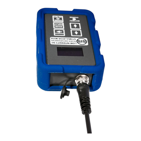
SIS SIS W250 User manual

SIS MACHINES
TECHNICAL OPERATING MANUAL_W250_v1.5
This operating manual is downloadable from http s ://www.siselectromed.com/
Due to periodic revisions, always check that you are reading the most up to
date version of this manual.
PLEASE READ THIS MANUAL CAREFULLY BEFORE USING THE SIS
EQUIPMENT FOR CORRECT AND SAFE OPERATION.
Page 1. SIS MANUFACTURING LTD, NZ. JANUARY 2019.

SIS MACHINE W250 MODEL OPERATING MANUAL
CONTENTS
SECTION PAGE
DEL VERY AND UNPACK NG_ _ _ _ _ _ _ _ _ _ _ _ _ _ _ 3
WARN NG FOR B OLOG CAL APPL CAT ONS_ _ _ _ _ _ 3
DEV CE DESCR PT ON_ _ _ _ _ _ _ _ _ _ _ _ _ _ _ _ _ _ 4
POWER SOURCE_ _ _ _ _ _ _ _ _ _ _ _ _ _ _ _ _ _ _ _ _ 4
ELECTRODE CABLE (HARNESS) CONNECT ON_ _ _ _ 4
KEYPAD CONTROLS AND OPERAT ON_ _ _ _ _ _ _ _ _ 5-6
APPL CAT ONS_ _ _ _ _ _ _ _ _ _ _ _ _ _ _ _ _ _ _ _ _ _ _ 6
Surface Wound, Surgical Wound, Skin Ulcer_ _ _ _ _ _ 6-11
DEV CE↔WOUND CAL BRAT ON_ _ _ _ _ _ _ _ _ _ _ 12
Tissue Regeneration_ _ _ _ _ _ _ _ _ _ _ _ _ _ _ _ _ _ _ 12-15
AUD O AND V SUAL ALERTS_ _ _ _ _ _ _ _ _ _ _ _ _ _ _ 16-17
ELECTROTHERAPY ELECTRODE↔SK N CONTACT_ _ 18
CONTRA ND CAT ONS AND SAFETY_ _ _ _ _ _ _ _ _ _ _ 19
MED CAL D SCLA MER _ _ _ _ _ _ _ _ _ _ _ _ _ _ _ _ _ _ 20
MA NTENANCE _ _ _ _ _ _ _ _ _ _ _ _ _ _ _ _ _ _ _ _ _ _ 21
WARRANTY_ _ _ _ _ _ _ _ _ _ _ _ _ _ _ _ _ _ _ _ _ _ _ _ _ 22
Returns, Disposal _ _ _ _ _ _ _ _ _ _ _ _ _ _ _ _ _ _ _ _ 23
DEV CE SPEC F CAT ONS _ _ _ _ _ _ _ _ _ _ _ _ _ _ _ _ 24
MANUFACTURER'S DECLARAT ON_ _ _ _ _ _ _ _ _ _ _ _ 25
Page 2. SIS MANUFACTURING LTD, NZ. JANUARY 2019.

SIS MACHINE W250 MODEL OPERATING MANUAL
DELIVERY AND UNPACKING
Please unpack the shipping package carefully and inspect contents
immediately on receipt. Check that all ordered equipment is included in the
shipping box and notify S S Manufacturing Ltd New Zealand immediately of
any missing items from your order.
Visible damage or tampering to shipping boxes must be recorded before
signing the delivery receipt. Please take photographs of any received
damaged items. Report the damage or tampering immediately to the shipping
carrier. You must also notify S S Manufacturing Ltd immediately of any
received damaged or tampered items or of any lost shipments.
WARNING FOR BIOLOGICAL APPLICATIONS
THE S S MACH NE MODEL W250 S ELECTRON CALLY CAL BRATED
W TH EXTREME PREC S ON FOR THERAPEUT C B OLOG CAL
ELECTRO-ST MULAT ON N COMB NAT ON W TH THE S S S LVER-
NYLON ELECTRODES. USE OF OTHER ELECTRODES CAN CAUSE
ADVERSE AND UNPRED CTABLE B OLOG CAL EFFECTS. FOR OTHER
B OLOG CAL ELECTRO-ST MULAT ON APPL CAT ONS, F S S S LVER-
NYLON ELECTRODES CANNOT OR ARE NOT USED, ONLY USE
SURFACE, NSERTED OR MPLANTED ELECTRODES APPROVED FOR
B OLOG CAL CONTACT AND MED CAL/THERAPEUT C APPL CAT ONS.
READ THE CONTRA ND CAT ONS AND SAFETY NSTRUCT ONS N TH S
MANUAL BEFORE US NG TH S EQU PMENT.
Page 3. SIS MANUFACTURING LTD, NZ. JANUARY 2019.

SIS MACHINE W250 MODEL OPERATING MANUAL
DEVICE DESCRIPTION
The S S machine model W250 is designed for electromedical low intensity
(amperage) direct current stimulation and silver iontophoresis for a surface
wound or ulcer, electromedical measurement, and supplementation or
replacement of endogenous wound bioelectrics, and stimulation of surface or
internal tissue fibroblast and other cell modifications and transdifferentiations.
1. POWER SOURCE
The W250 is powered by replaceable AAA type batteries. Rechargeable
batteries can be used and do not compromise the correct function of the
device. Refer to the DEV CE SPEC F CAT ONS section of this manual for
further information.
Do not use zinc-carbon batteries that can leak and damage the device.
1.1. INSERTING AAA BATTERIES
. POWER OFF the device if it is operating.
b. Remove the shockproof silicon cover from the casing.
c. Remove the battery compartment cover.
d. nsert 3×AAA batteries. Ensure correct polarity of the batteries—follow
the battery diagram and polarity symbols inside the battery
compartment.
e. Replace the battery compartment cover.
f. Replace the shockproof silicon cover over the casing.
2. ELECTRODE CABLE (HARNESS) CONNECTION
2.1. CONNECTION OF ELECTRODE CABLE TO SIS MACHINE
Unplug the Seal Cap from the connection socket (Jack) in the top end panel
of the device. nsert the cable connector plug all the way into the connection
socket. Screw tighten the Locking Ring on the cable connector plug to the
socket; DO NOT use excessive force.
2.2. CABLE TESTING
Perform a cable connection and integrity test from the CABLE TEST screen
before each application.
Page 4. SIS MANUFACTURING LTD, NZ. JANUARY 2019.

SIS MACHINE W250 MODEL OPERATING MANUAL
3. KEYPAD CONTROLS AND OPERATION
POWER
ON OFF
Power device on, 2 seconds hold.
Power device off, 5 seconds hold.
Main
Operating
Screen
Operational MODE displayed.
STATUS displayed.
PROGRAM Access Main
Menu
scroll
through Main
Menu options
EXIT
PROGRAM
to select
Return to Main Operating Screen.
WOUND Wound nd ulcer he ling oper tion l mode.
REGEN Tissue regener tion oper tion l mode.
STIM DATA
Output Current nd Volt ge
nd me sured bioelectric
d t
PROGRAM or
Return to Main
Menu
STATISTICS Electrode stimul tion
efficiency d t
CABLE TEST
Instructions 1
PROGRAM
Instructions 2
PROGRAM
Result:
PASSED or
FAILED
DISPLAY
AUTO-OFF (DEFAULT) or
ALWAYS ON
TIMER Session dur tion d t
MONITORING
AUTO (DEFAULT) or OFF
ABOUT Inform tion bout device
SOUND
──────
DISPLAY
ON or OFF (2 seconds hold)
OLED display turned ON or OFF (1 second hold) when D SPLAY set to
AUTO-OFF (DEFAULT)
The default device settings after powered on are OLED display and sound
turned on. f no keypad input is detected during operation with STATUS: OK
Page 5. SIS MANUFACTURING LTD, NZ. JANUARY 2019.

SIS MACHINE W250 MODEL OPERATING MANUAL
and the D SPLAY setting has not been changed from AUTO-OFF (DEFAULT),
then the display turns off after 2 minutes for power saving. At any time when
the menu is accessed, if no user input is detected after 1 minute, the device
automatically powers off.
The red BATTERY CHARGE LED flashes every 5 seconds while the device
is operating. The LED is not under user control.
3.1. ELECTRODE STIMULATION EFFICIENCY (ESE) MONITORING
The W250 monitors the contact of the S S or other electrode(s) with the body,
both in real-time and statistically via complex measurement, logging and
assessment algorithms with self-adaptive A aspects. The highly summarized
logged ESE data are shown in the STAT ST CS screen. ESE monitoring is
not under user control, except in REGEN mode when the device has
calibrated to internal fibrotic tissue; refer to the T SSUE REGENERAT ON
section of this manual for more guidance.
APPLICATIONS
4. Surf ce Wound, Surgic l Wound, Skin Ulcer
! NOTE: Apply standard, available procedures for cleaning/irrigating wounds.
Read and follow the NSTRUCT ONS FOR USE ( FU) on the FU card
included in each S S electrode pack. NOTE: The silver-nylon side of an S S
electrode is the active surface that contacts the body.
Position nd secure the SIS electrodes to the body first, nd then connect the
SIS electrode c ble to the two SIS electrode wires, nd oper te the W250.
4.1. ELECTRODE SIZE
The W250 c n more ccur tely monitor the electrode↔skin/wound cont ct
the sm ller the size of the electrodes. Do not use over-sized SIS electrodes:
select an electrode size that best matches the wound dimensions and
geometry. Use the S S Small round 4.75cm diameter electrode for most ⌀
small to medium size wounds. Use the 15×10cm Large rectangular S S
electrode for larger area wounds. Cut the (+)Positive Electrode to the size
and shape of the wound if necessary. For superficial wound applications, the
(-)Return Electrode can be smaller than the (+)Positive Electrode.
Page 6. SIS MANUFACTURING LTD, NZ. JANUARY 2019.

SIS MACHINE W250 MODEL OPERATING MANUAL
4.2. ELECTRODE POSITIONING
Diagrams of typical S S electrode positionings for wounds and ulcers:
https://siselectromed.com/wound-he ling-infected-wound-chronic-
wound-di betic-ulcer/
For e ch electrode pl cement, follow SECURING ELECTRODES
instructions.
! NOTE: SUPERF C AL WOUND electrode positioning has the strong
advantage of not contacting the wound bed and so not mechanically
interfering with the formation of granulation tissue.
4.2.1. SUPERFICIAL WOUND (INFECTED)
A. Position the S S (+)Positive Electrode onto the surrounding normal tissue
as close as possible/no more than 2cm (3/4") from the edge of the
wound; place electrode carefully not to physically disturb the wound.
B. Position the S S (-)Return Electrode onto intact skin as much as possible
directly behind the center of the wound on the opposite anatomical
surface of the injured body part.
NOTE: f SUPERF C AL WOUND electrode positioning is not achievable (e.g.
due to a wound dressing considered not removable), or if the NO WOUND or
CANNOT CAL BRATE alerts cannot be corrected, then follow 4.9. WOUND
STER L ZAT ON instructions. Revert to SUPERF C AL WOUND electrode
positioning when possible.
ROTATIONAL (+)POSITIVE ELECTRODE POSITIONING
For a larger superficial wound, depending on the limitations of wound location
and geometry, each time the S S (+)Positive Electrode is replaced, it can be
advantageous to re-position the (+)electrode at a different o'clock location
around the wound edges, for example in the repeating sequence: 3-6-9-12
o'clock, in order to distribute stimulation evenly to the entire wound, over time.
The (-)Return Electrode should remain in the same location throughout.
Page 7. SIS MANUFACTURING LTD, NZ. JANUARY 2019.

SIS MACHINE W250 MODEL OPERATING MANUAL
4.2.2. DEEPER WOUND (INFECTED)
A. Rinse the S S (+)Positive Electrode with saline/sterilizing fluid if available.
Position the electrode directly onto the wound bed; the electrode should
not extend beyond wound edges or as minimally as possible.
B. Cover the S S (+)Positive Electrode with saline/sterilizing liquid-rinsed
gauze or other non-adherent moisture-holding wound dressing if
available.
C. Position the S S (-)Return Electrode onto intact skin as much as possible
directly behind the center of the wound on the opposite anatomical
surface of the injured body part.
NOTE: f DEEPER WOUND electrode positioning is not achievable (e.g. due
to a wound dressing considered not removable), apply SUPERF C AL
WOUND electrode configuration. Revert to DEEPER WOUND electrode
positioning when possible.
Page 8. SIS MANUFACTURING LTD, NZ. JANUARY 2019.

SIS MACHINE W250 MODEL OPERATING MANUAL
4.2.3. FIRST AID: SIS (+)POSITIVE ELECTRODE ONLY (A) OR
WITH SIS (-)RETURN ELECTRODE AND SIS MACHINE (A, B)
A. Select an S S (+)Positive Electrode large enough to cover the entire
wound and extending at least 2cm (3/4") beyond the edges of the wound
on all sides. Position the electrode directly over the wound.
B. Position the S S (-)Return Electrode onto intact skin as much as possible
directly behind the center of the wound on the opposite anatomical
surface of the injured body part.
4.3. SECURING ELECTRODES
The contact of the entire surface of an S S electrode positioned onto normal,
intact (i.e. non-damaged) skin should be as uniform as possible to surface
anatomy geometry.
Use adhesive fixation tape, stretch strap, bandages or other emergency
means to secure the electrode to the body:
➔When positioning an S S electrode onto normal intact skin, extend the
dressing tape beyond all edges of the electrode.
➔When positioning an S S electrode onto periwound/adjacent-wound-
edge tissue, if it is impossible to extend the dressing tape beyond the
edge of the S S (+)Positive Electrode adjacent to the wound edge
without physically disturbing the wound, do not extend the dressing tape
beyond this edge of the electrode.
4.4. CONNECTION OF ELECTRODE CABLE TO ELECTRODES
4.4.1 ELECTRODE CABLE POLARITY
●The S S electrode that is connected to the red wire of the electrode
harness is the S S (+)Positive Electrode.
●The S S electrode that is connected to the bl ck wire of the electrode
harness is the S S (-)Return Electrode.
nsert the two gold metal 'banana plugs' at the ends of the electrode cable
into the two white plastic connectors at the ends of the S S electrode wires;
insert the 'banana plugs' all the way in until they are no longer visible.
Page . SIS MANUFACTURING LTD, NZ. JANUARY 2019.

SIS MACHINE W250 MODEL OPERATING MANUAL
NOTE: Do not tape the connections of the electrode cable to the electrode
wires as doing so can cause excessive mechanical force on the cable
connection to the electro-stimulator.
4.5. OPERATIONAL MODE
Select WOUND operational mode. Follow on-screen alert messages.
Page 10. SIS MANUFACTURING LTD, NZ. JANUARY 2019.

SIS MACHINE W250 MODEL OPERATING MANUAL
4.6. WOUND STERILIZATION
This application should only be used for a surface wound or ulcer if
SUPERF C AL WOUND and DEEPER WOUND applications are not
technically achievable. The application can only be used if a starting, total
circuit resistance of <40 kΩ can be achieved; the actual measured total circuit
resistance value is shown in the ST M DATA screen as RES.
Refer to the ELECTROTHERAPY ELECTRODE↔SK N CONTACT section of
this manual for further information.
A. Position the S S (+)Positive and (-)Return Electrodes on opposite sides
across the wound as close as possible to the wound edges; position the
(+)Positive Electrode closest to the most infected side of the wound.
4.6.1. OPERATIONAL MODE
Program REGEN operational mode.
PROGRAM a 1.5cm² electrode size (default).
! IMPORTANT INFORMATION:
MAXIMUM RECOMMENDED SIS ELECTRODE LIFETIME FOR WOUND
AND ULCER TREATMENT:
SIS (+)POSITIVE (RED WIRED) ELECTRODE: 12-24 HOURS
SIS (-)RETURN (BLACK WIRED) ELECTRODE: 12-48 HOURS
Page 11. SIS MANUFACTURING LTD, NZ. JANUARY 2019.

SIS MACHINE W250 MODEL OPERATING MANUAL
5. DEVICE↔WOUND CALIBRATION
The following table gives further guidance on how to improve device-to-
wound calibration if the NO WOUND or CANNOT CAL BRATE alerts cannot
be corrected, even after re-checking the appropriate wound applications
instructions and device application re-attempts have failed:
WOUND DEPTH NCREAS NG
CONDUCT V TY
(+)ELECTRODE
POS T ON NG
AND S ZE
OTHER
ACT ONS
SUPERF C AL Wet the periwound/
adjacent-wound-
edge tissue with
saline or clean
water if available.
Move closer to the
wound edge.
Cut down electrode to
a smaller size.
Debride
wound if
appropriate
physician
or wound
nurse only.
DEEP Moisten wound bed
with saline or clean
water if available.
Check electrode does
not extend beyond
wound edges.
Refer to the ELECTROTHERAPY ELECTRODE↔SK N CONTACT section of
this manual for further information.
6. TISSUE REGENERATION
6.1. INTERNAL FIBROTIC TISSUE
6.1.2. ELECTRODE POSITIONING
The S S (+)Positive Electrode must completely 'cover' the target internal
organ or other anatomical structure. The electrode must be at least the same
size or slightly larger than the target internal organ or other anatomical
structure as it would be seen 2-dimensionally in a diagnostic X-ray/CAT scan/
MR scan/ultrasound taken from the position and anatomical plane of the
electrode on the body surface.
A. Position the S S (+)Positive Electrode onto intact skin skin directly over
the target infected organ or other anatomical structure.
B. Position the S S (-)Return Electrode onto intact skin on the opposite
anatomical surface of the body to the S S (+)Positive Electrode so that
the target infected organ or other anatomical structure is aligned bet ween
the two S S electrodes.
Page 12. SIS MANUFACTURING LTD, NZ. JANUARY 2019.

SIS MACHINE W250 MODEL OPERATING MANUAL
Follow 4.4. CONNECT ON OF ELECTRODE CABLE TO ELECTRODES
instructions.
6.1.3. OPERATIONAL MODE
Select REGEN operational mode.
6.1.4. SELECT (+)POSITIVE ELECTRODE SIZE
Select and program the S S (+)Positive Electrode size.
6.1.5. CONSTANT CURRENT SCALING
The output CURRENT is automatically scaled to the user-programmed
surface area size of the S S (+)Positive Electrode, as shown below and in
real-time in the ST M DATA screen. The smallest electrode that can be
programmed is 1.5 cm²; the maximum size of any electrode shape is 50 cm²:
f a standard 4.75cm (1.87") ⌀diameter Small circular S S electrode is used,
which has an actual surface area of 17.7cm² [πr2], select and program its
approximate surface area of 20cm². Similarly, for an irregular shaped S S
electrode cut to the size of an injured tissue area, calculate and program its
approximate overall surface area.
6.1.5.1. To override the automatic constant output current scaling for any
reason, select and program either a larger or smaller S S (+)Positive
Electrode than actually used. For example, to program an output current of 60
microAmps for an actually used 30cm² S S (+)Positive Electrode, select and
program a 40cm² (+)Positive Electrode size.
Page 13. SIS MANUFACTURING LTD, NZ. JANUARY 2019.

SIS MACHINE W250 MODEL OPERATING MANUAL
6.1.6. TOTAL CIRCUIT RESISTANCE OPERATING LIMITS
The total circuit resistance operating limit of the W250 for all possible user-
programmed S S (+)Positive Electrode sizes is shown in the table below; the
actual measured total circuit resistance is shown in real-time in the ST M
DATA screen as RES.
(+)Positive
Electrode
surf ce re
(cm²)
1.5 2.5 5 10 15 20 25 30 35 40 45 50
Tot l circuit
resist nce
oper ting limit
in kΩ(MΩ)
(3.4) (2) (1) 500 333 250 200 166 142 125 111 100
f the total circuit resistance shown in the ST M DATA screen cannot be
maintained continuously below the corresponding operating limit, treat a
smaller target internal fibrotic tissue area at one time with a smaller
(+)Positive Electrode size.
NOTE: Total circuit resistance values above 100kΩ will trigger cautionary
H GH RES STANCE device alerts; refer to section 7. AUD O AND V SUAL
ALERTS for further guidance.
Also refer to the ELECTROTHERAPY ELECTRODE↔SK N CONTACT
section of this manual for further information.
Page 14. SIS MANUFACTURING LTD, NZ. JANUARY 2019.

SIS MACHINE W250 MODEL OPERATING MANUAL
6.2. SURFACE INJURED TISSUE
6.2.1. ELECTRODE POSITIONING
A. Follow DEEPER WOUND instructions for positioning the S S
(+)Positive and (-)Return Electrodes to the surface injured tissue.
B. The starting, total circuit resistance must be <40 kΩ for operation to
begin; if >40KΩ, operation automatically switches to the NTERNAL
F BROT C T SSUE mode. The total circuit resistance value is shown in
real-time in the ST M DATA screen as RES.
6.2.2. OPERATIONAL MODE
Select REGEN operational mode.
6.2.3. (+)POSITIVE ELECTRODE SIZE
There is no user selection of S S (+)Positive Electrode size. The output
voltage self-adaptively scales to the injured tissue's bioelectric properties.
Page 15. SIS MANUFACTURING LTD, NZ. JANUARY 2019.

SIS MACHINE W250 MODEL OPERATING MANUAL
7. AUDIO AND VISUAL ALERTS
Alert Message Meaning / Notes Action Required
STANDBY CAL BRAT NG Device is calibrating to
wound or internal tissue
target pathway.
Wait.
STATUS: OK Device is operating within
normal limits. Electrode
contact is established.
None.
MODE: WOUND BED WOUND mode is activated
and the device has
calibrated to the wound
bed.
No action is required if the
(+) electrode is positioned at
the wound edge or on the
wound bed.
MODE: WOUND EDGE WOUND mode is activated
and the device has
calibrated to the wound
edge.
No action is required if the
(+) electrode is positioned at
the wound edge.
f the(+) electrode is
positioned on the wound
bed, recheck 4.2.2.
DEEPER WOUND
instructions.
STATUS: ALERT Problem detected with
electrode contact.
Follow alert message
instructions.
POOR CONTACT Electrode contact is
immediately or statistically
insufficient for therapeutic
effect, due to mechanical
(physical) and/or electro-
chemical factors.
Follow alert message
instructions.
Replace or apply additional
dressing tape to electrodes
(pads) if necessary. f in
WOUND operational mode,
see 5. DEV CE↔WOUND
CAL BRAT ON instructions.
UNSTABLE CONTACT Electrode contact is varying
too rapidly for therapeutic
effect.
C RCU T BREAK No electrical stimulation
circuit.
Follow alert message
instructions.
H GH RES STANCE Cautionary alert only.
Device is operating within
normal limits. Alert will
automatically de-activate
after 30 seconds.
Follow alert message
instructions.
Check skin for redness or
other signs of irritation.
BATTERY CHARGE LOW Remaining charge in the
replaceable batteries below
minimum operating level.
Replace batteries. Refer to
DEV CE SPEC F CAT ONS.
Page 16. SIS MANUFACTURING LTD, NZ. JANUARY 2019.

SIS MACHINE W250 MODEL OPERATING MANUAL
NO WOUND No wound detected from
electrode placement.
Wait for device to power off.
Re-check appropriate
application instructions. f in
WOUND operational mode,
see 5. DEV CE↔WOUND
CAL BRAT ON instructions.
Power on device again if
necessary.
CANNOT CAL BRATE Device cannot calibrate
due to alerted, uncorrected
electrode contact problem.
POWER NG OFF The device is about to
automatically power off due
to uncorrected alert status,
lack of user activity, low
battery charge, or user
powering down the device.
Page 17. SIS MANUFACTURING LTD, NZ. JANUARY 2019.

SIS MACHINE W250 MODEL OPERATING MANUAL
8. ELECTROTHERAPY ELECTRODE↔SKIN
CONTACT
Electrical resistance, which is part of total electrical impedance to the flow of
electric current, is measured in units of Ohms (Ω):
1 megaOhm (MΩ) = 1000 kiloOhm (kΩ) = 1,000,000Ω
The total circuit resistance during non-invasive electrotherapy stimulation via
any pair of any type of electrotherapy electrode is the sum of the electrical
resistances at both the electrode↔skin/body contact areas, plus the internal
body electrical resistance(s) in the pathway(s) of electric current between the
two electrodes. Large variations in total circuit resistance up in to the MΩ
range can occur depending on many device-related and bioelectric factors.
NOTE: A major factor that affects electrode↔skin/wound contact area
electrical resistances is moisture; the wetter these areas the lower their
contributing electrical resistances to the total circuit resistance.
B OELECTR C WOUND ASSESSMENT: Bioelectrically, as a wound or ulcer
heals, the through-wound electrical resistance linearly increases. f the
electrode↔skin/wound contact electrical conductivity factors are held
relatively constant over time, or if their known dynamics are calibrated out of
the total circuit resistance measurements, the target through-wound electrical
resistance measurements can be reliably obtained, at regular measurement
intervals. This methodology can enable bioelectric data based assessment of
(rate of) wound healing.
W250 FUNCTIONS
Total circuit resistance is shown in the ST M DATA screen as RES and
updates every 30 seconds with an average value of multiple real-time
measurements. The W250 continuously and rapidly self-adapts to the
electrical resistance dynamics of the electrode↔skin/wound contact areas.
The device-generated Output Voltage is shown in the ST M DATA screen as
VOLTS. An Output Voltage level and spike monitoring algorithm assesses 10
minute stimulation periods at a time, and is calibrated in relation to a
relatively low ≤ 50-100 kΩ RES value, in order to assess early possibility of
intact (non-wound) skin irritation during extended device application.
Page 18. SIS MANUFACTURING LTD, NZ. JANUARY 2019.

SIS MACHINE W250 MODEL OPERATING MANUAL
9. CONTRAINDICATIONS AND SAFETY
DO NOT POS T ON ELECTRODES OVER THE BRA N. CONSULT W TH A
SPEC AL ST HEALTHCARE PROFESS ONAL BEFORE APPL CAT ON.
DO NOT POS T ON ELECTRODES OVER THE HEART (CENTRAL AND
LEFT S DE OF CHEST). CONSULT W TH A SPEC AL ST HEALTHCARE
PROFESS ONAL BEFORE APPL CAT ON.
DO NOT POS T ON ELECTRODES ON THE ABDOMEN F THE SUBJECT
S PREGNANT OR M GHT BE PREGNANT.
DO NOT POS T ON ELECTRODES NEAR A PACEMAKER OR OTHER
MPLANTED ELECTRO-ST MULATOR. CONSULT W TH A SPEC AL ST
HEALTHCARE PROFESS ONAL BEFORE APPL CAT ON.
DO NOT POS T ON ELECTRODES ACROSS THE EYES. CONSULT W TH
A SPEC AL ST HEALTHCARE PROFESS ONAL BEFORE APPL CAT ON.
DO NOT POS T ON ELECTRODES ACROSS THE ANTER OR NECK
(CAROT D S NUS). CONSULT W TH A SPEC AL ST HEALTHCARE
PROFESS ONAL BEFORE APPL CAT ON.
DO NOT USE THE ELECTRO-ST MULATOR F THERE S A H STORY OF
SE ZURES. CONSULT W TH A SPEC AL ST HEALTHCARE
PROFESS ONAL BEFORE APPL CAT ON.
DO NOT EXPOSE THE ELECTRO-ST MULATOR TO WATER.
D SCONNECT ELECTRODES FROM HARNESS (CABLE) OR REMOVE
FROM BODY WHEN ENTER NG WATER.
DISCONTINUE USE F SK N RR TAT ON OCCURS.
KEEP AWAY FROM CHILDREN.
Page 1 . SIS MANUFACTURING LTD, NZ. JANUARY 2019.

SIS MACHINE W250 MODEL OPERATING MANUAL
8. MEDICAL DISCLAIMER
NO ADV CE
nformation provided for education and research information only. This
manual contains general information about medical conditions and
treatments. The information is not advice, and should not be treated as such.
The information in this manual is made available on the basis that no
professional advice on a particular medical matter is being provided. No
liability is accepted for any injury, loss or damage incurred by use of or
reliance on the information provided in this manual.
PROFESS ONAL ASS STANCE
You must not rely on the information in this manual as an alternative to, or
substitute for, medical advice from your professional healthcare provider. f
you have any specific questions about any medical matter you should consult
your professional healthcare provider. f you think you may be suffering from
any medical condition you should seek immediate medical attention. You
should never delay seeking medical advice, disregard medical advice, or
discontinue medical treatment because of information in this manual.
L M TAT ON OF WARRANT ES
The medical information in this manual is provided “as is” without any
representations or warranties, express or implied. S S Manufacturing Ltd NZ
makes no representations or warranties in relation to the medical information
in this manual. Without prejudice to the generality of the foregoing paragraph,
S S Manufacturing Ltd NZ does not warrant that: the medical information in
this manual will be constantly available, or available at all; or the medical
information in this manual is complete, true, accurate, up-to-date, or non-
misleading. Nothing in this medical disclaimer will limit any of the liabilities of
S S Manufacturing Ltd NZ in any way that is not permitted under applicable
law, or exclude any of its liabilities that may not be excluded under applicable
law.
Page 20. SIS MANUFACTURING LTD, NZ. JANUARY 2019.
This manual suits for next models
1
Table of contents
Other SIS Medical Equipment manuals
Popular Medical Equipment manuals by other brands

BIOTRONIK
BIOTRONIK CardioMessenger Smart Technical manual

Storz
Storz CALCULASE instruction manual

VSSI
VSSI V-Top instruction manual

Carestream
Carestream DRX-Revolution Hardware guide

ErgoCentric
ErgoCentric Multi Tilt user guide

Baxter Healthcare Corporation
Baxter Healthcare Corporation Colleague Operator's manual