Siser TS DUE User manual

This manual is the property of SISER S.r.l., any even partial reproduction is forbidden
Mod. PRD 22 rev.2 - last updating: 01/2015
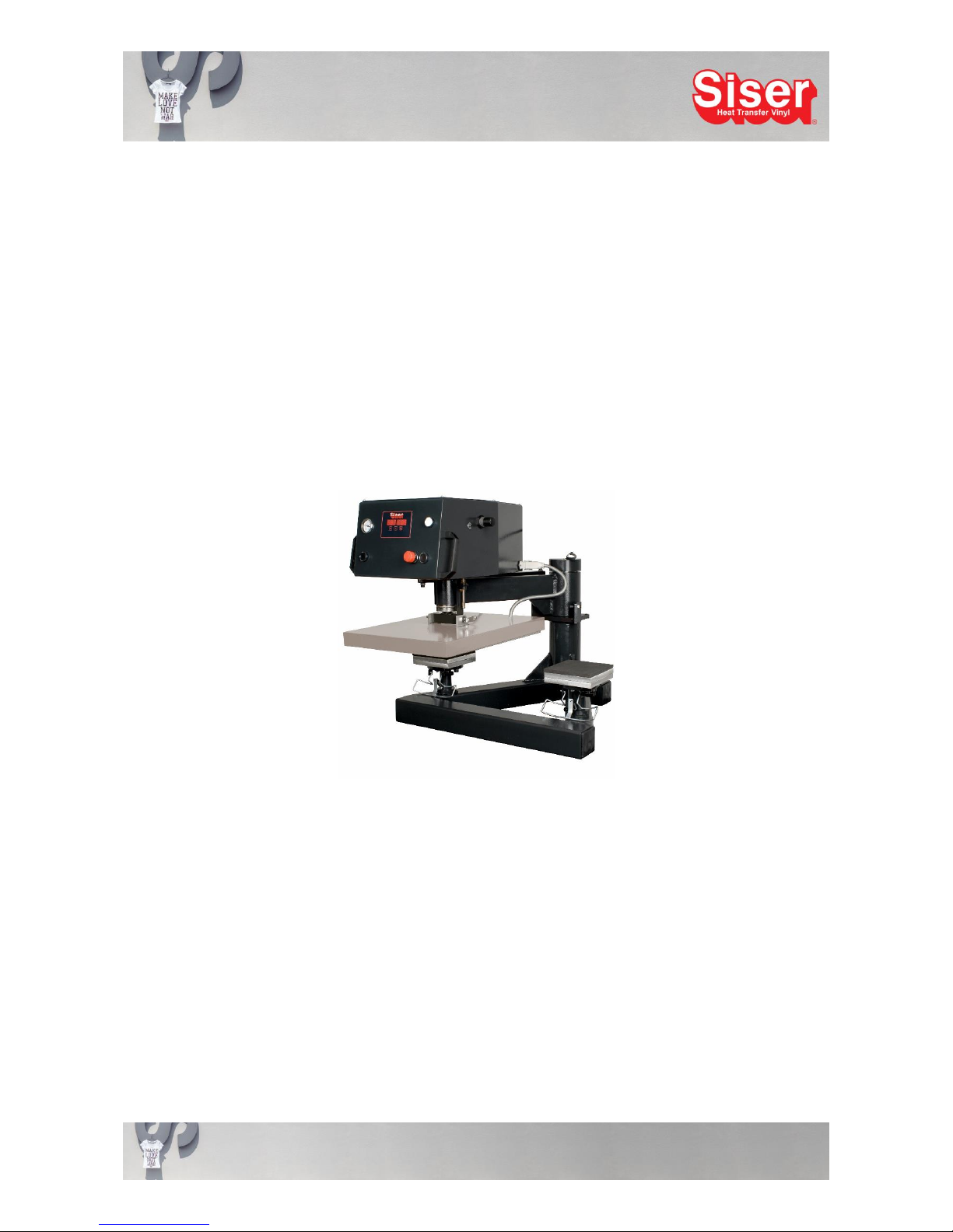
OPERATING INSTRUCTIONS FOR PNEUMATIC
Heat Transfer Press
TS DUE
with interchangeable plates

This manual is the property of SISER S.r.l., any even partial reproduction is forbidden
Mod. PRD 22 rev.2 - last updating: 01/2015
Thank you very much for buying one of our Siser TS DUE heat transfer presses.
We are sure you will capitalise on this excellent unit for years if you take the time to read these instructions
carefully.
Introduction
Please study these instructions carefully before transporting, mounting, using or maintaining the transfer press,
as they will give you important directions for a safe handling. Moreover you will find information about how to
order spare parts in this manual. Please retain these instructions for later reference in a safe, easily accessible
place. Please make sure that all operators of the transfer press have understood all instructions and graphic
symbols labelled on the press.
Accidents can also be avoided by strictly following the safety regulations according to the machine directive
89/37/CEE replaced by 2006/42/CEE - 73/23/CEE replaced by LVD 2006/95/CEE –89/336/CEE replaced by
EMC 2004/108/CEE –EN 292/1 –EN 292 replaced by UNI EN ISO 12100 and UNI ENI ISO 12100-2 –EN
60204.
It is specifically prohibited to remove or manipulate shrouds or legally compulsory labels or plates.
Contents
1. Warranty
2. Technical Data
3. Cap and Plate Sets
4. Operating the Transfer Press
5. Safety Regulations
6. Mounting, Transport and Mounting Location
7. Electrical Connection
8. Directions for Use
9. Maintenance
10. Dismantling and Disposal of Transfer Press
11. Spare Parts List
12. Exploded View
13. Electronic Diagram
14. Electronic Diagram board S2
15. Pneumatic Diagram
This manual is the property of SISER S.r.l., any even partial reproduction is forbidden
Mod. PRD 22 rev.2 - last updating: 01/2015
1. Warranty
Siser provide you with a 12 months warranty on all their transfer presses
(from date of purchase).
To submit a warranty claim is only possible if the transfer press has been mounted and used according to the
instructions in this manual and all necessary maintenance has been regularly performed.
During the warranty period defective or broken parts will be repaired free of charge by Siser Italy.
Transport and shipping expenses are on buyer's account.
The reclaim of defective parts after their replacement is at the discretion of Siser.
Parts needing to be replaced because of maintenance, wear or carelessness are not included in this warranty.
Any claims of consequential costs of a loss or damage, e.g. loss of production, are explicitly excluded from
this warranty. No distributor, representative or agent is authorised to assume for Siser any other obligation or
liability or to submit a statement different from the one mentioned above.
By accepting this warranty the customer waives every compensation for losses or damages arising from a
production stop.
2. Technical Data
Mains Voltage 220 V
Power Consumption 2000 W
Weight 75 Kg
Size of Supporting Plate 2 x (40 x 50 cm)
Printing Pressure 1.2-1.5 kg/cm2–2.5-10 bar
Max. Temperature 250 °C
This manual is the property of SISER S.r.l., any even partial reproduction is forbidden
Mod. PRD 22 rev.2 - last updating: 01/2015
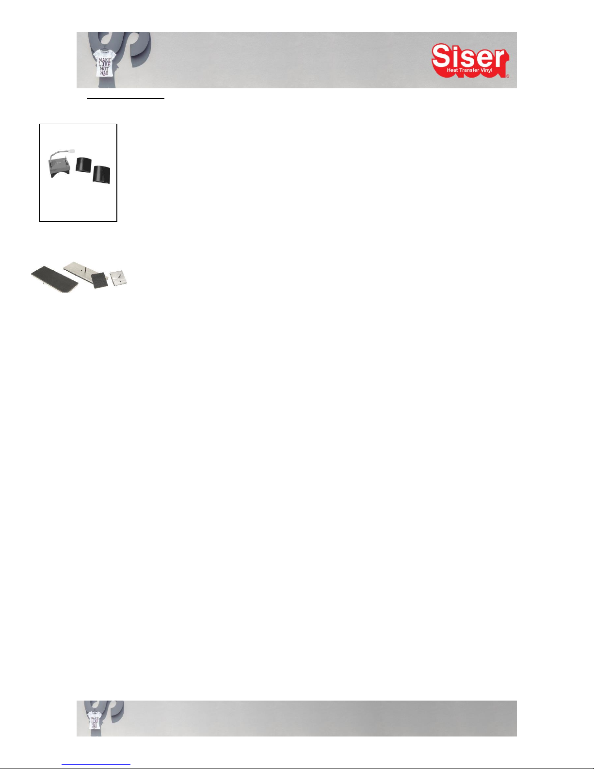
3. Cap and Plate Set
For this model you may purchase easily interchangeable sets for
converting the press:
A. Cap set with a bent heating plate and two supporting plates (cf. fig. a)
B. Plate set (cf. fig. b) consisting of :
a supporting plate sized 15 x 38 cm
e.g. for trouser legs or sleeves and
a supporting plate sized 15 x 15 cm
e.g. for shirt pockets
C. We'll be happy to produce plates in other sizes for you upon request.
Fitting and Connecting the Cap Set
Before fitting the cap set ensure that the unit is cold and switched off. Then unplug the cable between heating
plate and instrument box. Now untighten the clamping element of the heating plate suspension, remove the
heating plate with care and put it down on a safe, even surface.
Fit the bent heating cap plate in place of the normal heating plate and tighten it to the suspension using the
clamping element. Then connect the heating element to the instrument box by plugging in the connector into
the socket. The heating element is now ready for use. After that install the bent supporting cap plates observing
the following instructions:
To exchange the flat supporting plates with bent cap supporting plates untighten the two fixing screws just
underneath the supporting plates, remove the flat plates and fit the bent cap plates in the same way. Please
do not forget to tighten the plates again.
b. Plate set for sleeves,
trousers and pockets.
a. Cap Set twin
This manual is the property of SISER S.r.l., any even partial reproduction is forbidden
Mod. PRD 22 rev.2 - last updating: 01/2015
Fitting the Plate Sets
For fitting the various supporting plates untighten the two fixing screws just underneath the supporting plates.
Now you can swap the present supporting plate for a plate of your choice and fix the new plate by tightening
the fixing screws.
It is not necessary to swap the heating plate, even if the heating plate sticks out in case of smaller supporting
plates. However you should never use the bent supporting cap plate together with a flat heating plate for t-
shirts.
TS DUE with plates cm. 15x15

This manual is the property of SISER S.r.l., any even partial reproduction is forbidden
Mod. PRD 22 rev.2 - last updating: 01/2015
TS DUE with plates cm. 15x38
TS DUE with cap set
This manual is the property of SISER S.r.l., any even partial reproduction is forbidden
Mod. PRD 22 rev.2 - last updating: 01/2015
4. Operating the Transfer Press
This transfer press can be used for transferring thermically weldable materials onto any kind of textiles.
Not more than one person may operate the press at a time. Avoid exceeding the specified maximum
temperature when operating the press.
Siser is not liable for faults, accidents, damages, losses etc. resulting from not following the instructions in this
manual.
Note: It is strictly forbidden to operate or mount this transfer press contrary to the directions made in this
manual.
5. Safety Regulations
Before operating the transfer press, the operator must have fully understood the handling and function of the
electric components of this transfer press and must have read and grasped all information provided in this
manual.
NOTE: There is the risk of getting burned if you touch the heating plates during operation. We strongly
advise the operator to wear protective gloves providing protection up to a temperature of 250° C.
Avoid to touch the heating plates of the transfer press during operation and for a period of 15 minutes after the
press has been switched off, as the operating temperature of the press is very high. Please also avoid to touch
the lower supporting plates when closing the press or printing the textile, as these operations involve a risk of
getting squashed and burned.
It is strongly recommended that only one person operates the transfer press.
Any kind of maintenance and / or repair work on the transfer press must only be performed after the
heating plate has been switched off and has cooled down to ambient temperature.
Do not use the transfer press in a humid or wet environment. Before swapping the heating plates, switch off
the unit and allow it to cool down to ambient temperature.
To not perform any transfers to textiles containing solvents, flammable liquids, gaseous or liquid fuels.
Unauthorised changes of the unit or the replacement of parts without consent of Siser srl are prohibited.
Siser srl is not liable for damages, losses, injuries or consequential damages resulting from
acts, changes or other use of the transfer press not authorised by a prior written consent from
Siser srl.
All mounting, maintenance and repair work must be performed only by skilled and specially trained electricians.
It is strictly prohibited to remove or manipulate any kind of safety appliances.
The working area must be clean, tidy and free of any obstacles for manoeuvring the heat transfer press.
All general instructions for operation and all safety instructions must be strictly followed to avoid any
injuries that might result from the use of this transfer press and to ensure a successful utilisation of
the press.
This manual is the property of SISER S.r.l., any even partial reproduction is forbidden
Mod. PRD 22 rev.2 - last updating: 01/2015
6. Mounting, Transport and Mounting Location
The installation of the transfer press must only be performed by suitably qualified personnel, as the electrical
connections must comply with local regulations.
Before mounting the transfer press prepare a suitable mounting location. Handle the package containing the
transfer press with care and with the aid of suitable tools. As the transfer press is heavy, the mounting should
be performed by two people.
For the mounting location you need a stable table with a height of approximately 70 cm. Fixing the unit's feet
to the table top is a good way to increase the safety of the unit particularly if the work table is mobile.
7. Electrical Connection
The transfer press must be mounted in a room featuring a power supply system approved by local authorities
and complying with effective safety regulations for electric devices.
The available power supply lines must have a cross section sufficient for the transfer press's energy demand
of 2 kW, preferably in its own power circuit. The characteristic values of the power supply system must comply
with the characteristics of the heat transfer press. Please check the values stated on the label.
The coloured conductor markings must be carefully complied with and the transfer press must be earthed.
Please refer to EN 60439 –1 (CEI 17-13/1).
The power socket must have an electric protective earthing and a residual-current-operated protective device
(RCD) disconnecting the circuit if the residual current exceeds 30 mA.
Do not use cables with damaged insulation. It is inadvisable to use extension cords.
Remove the plug from the power socket before starting any maintenance or repair work, in particular
if it is necessary to open the box of the control panel or to perform work on the heating elements.
The graphic symbol „High-Tension“ signalises a serious danger and is attached on the box of the control panel
and on top of the heating elements. Switch off the master switch before exchanging or removing heating
elements.
8. Directions for Use
Please note the risks involved in using a transfer press mentioned in paragraph 4 of this manual, in
particular
the risk of squashing your hands in between the plates
the risk of an electric shock
the risk of burning your hands and arms on the heating plates
Wear protective gloves to avoid the risk of getting burned.

This manual is the property of SISER S.r.l., any even partial reproduction is forbidden
Mod. PRD 22 rev.2 - last updating: 01/2015
Implementing the Transfer Press
1) Plug the connector cable into a power socket of 220 V.
2) Open the air tap for the filter controller upwards.
3) Set the master switch from 0 to 1.
4) Check the connection between heating plate and control unit. Is the 6 pole connector securely plugged
into the socket of the control unit?
5) Set the desired temperature.
6) Set the desired pressing time on the timer.
7) Adjust the incoming pressure at the instrument on the upper left side of the press. The printing pressure
is shown on the manometer and can be adjusted using the pressure controller. To adjust the pressure,
pull the pressure controller outwards and turn it
-clockwise to increase the pressure
-anti-clockwise to reduce the pressure
After you have set the pressure, push the controller back into its original position.
8) Adjust the “real“ printing pressure by turning the pressure controller on the right upper side of the press.
To adjust the pressure turn it
-clockwise to increase the pressure
-anti-clockwise to reduce the pressure
9) Place the textile to be printed on the lower plate and position the plotted transfer onto it. Swivel the upper
heating plate above the prepared lower supporting plate using the handles fixed to the side of the heating
plate.
10) Press the two push buttons located on both sides of the pressure arm simultaneously. The heating plate
will descend and after the pressing time has elapsed, it will be lifted automatically in its original position.
The press is now ready for a new transfer process.
11) A new feature of TS DUE is the yellow stop-button in front of the heat press, which allows a stop of the
pressing-process at any time. This can be used for any pre- or post-pressure situation. Just push the
button to stop the pressing-process.
12) Switch off the transfer press when you do not use it.
WE HIGHLY RECOMMEND NOT TO TOUCH THE AIR FLOW CONTROLLER IN THE FILTER GROUP!

This manual is the property of SISER S.r.l., any even partial reproduction is forbidden
Mod. PRD 22 rev.2 - last updating: 01/2015
Operating Parameters
Please set the operating parameters (time and temperature) by using the display and the LEDs on the control
panel.
Annotations
1. After you have pressed the "S" button (SET), "01" starts flashing on the display. When the flashing has
stopped, set the desired temperature in Celsius on the electronic display: "+" rises the temperature, "-"
lowers the temperature. When the desired temperature is reached, confirm by pressing the "S" button.
2. After that you have to set the desired pressing time in seconds: "+" extends the time, "-" reduces the time.
If the switch is pressed a second time, the data is saved and the temperature set before is shown again
on the display. The heat transfer press is ready for use as soon as the desired temperature is reached.
It is always possible to check time and temperature by tapping the "S" button.
Working programms
With the new control board TS2 3P 4 different programs may be saved: the standard program in addition to 3
new programs dedicated to Flock, Flex or Sublimation transfers. Thanks to this new system you only need to
enter the right parameters in order to transfer quickly.
Parameter adjustment
Standard-program (00)
Please press the button Sfor 25/30 seconds. The display confirms the access to the program by showing 00
followed by a flashing and audible signal.
In order to modify the program, please press again the button S for 25/30 seconds.
Flex-Program (01)
Press button S
The display shows up 01, followed by the audible signal and blinking
On the display the preset parameters appear: 160°C and 15 seconds
Flock-Program (02)
Press button S
The display shows up 02, followed by the audible signal and blinking
On the display the preset parameters appear: 150°C and 15 seconds

This manual is the property of SISER S.r.l., any even partial reproduction is forbidden
Mod. PRD 22 rev.2 - last updating: 01/2015
Sublimation-program (03)
Press button S
The display shows up 03, followed by the audible signal and blinking
On the display the preset parameters appear: 200°C and 60 seconds
The operator may change the preset parameters with buttons „+“ and „-„.
The modified parameters may be saved directly by pressing button Sand may
always be recalled and altered again.
The preset temperature may be modified in each program (01…02…03) plus or
minus 20 °C. For the standard program however, temperatures between 0°C and 250° may be adjusted.
Display signals
In case of failures, the new control board TS2 3P gives different signals in order to
discover and resolve the problem immediately.
If 111 appears on the display and the light blinks, followed by an acoustic
signal, the temperature sensor is defect or not connected with the control board.
If 000 appears on the display and the light blinks, followed by an acoustic
signal, the temperature ranges about 15°C because of a default. The control board has to be checked.
9. Maintenance
Following the safety directions mentioned below is essential to avoid severe injuries to the operator and / or
damage to the transfer press.
Before performing any maintenance work, the transfer press must have been switched off and the plug
must have been removed from the power socket.
Note the high temperatures of the heating plate (top). It can take up to 15 minutes until the plate has cooled
down to a temperature below 50° C.
Carefully follow the instructions mentioned in this manual before performing any maintenance or cleaning work
on the transfer press.
Maintenance work must only be performed by skilled and specially trained staff.
Before switching on the unit again after maintenance or cleaning work, ensure that no tools or spare parts
have been left in or on the unit and that shrouds, safety appliances, graphic symbols and instructions attached
to the press are in good condition and easy to read.

This manual is the property of SISER S.r.l., any even partial reproduction is forbidden
Mod. PRD 22 rev.2 - last updating: 01/2015
10. Dismantling and Disposal of the Transfer Press
All work for dismantling or disposal must be performed by sufficiently qualified staff.
A transfer press is an industrial unit. All applicable laws concerning the disposal of industrial machinery in the
country of the user must be followed.
Disconnect the unit from the power supply and dismantle it. Sort the parts according to their composition, e.g.
aluminium, plastic, steel, mineral wool etc. The disposal of these material groups must be performed in
accordance to the applicable laws in the country of the user.
Strictly follow the safety instructions mentioned in this manual when dismantling the press.
This manual is the property of SISER S.r.l., any even partial reproduction is forbidden
Mod. PRD 22 rev.2 - last updating: 01/2015
11. Spare Parts List
1. base
2. swivel pin
3. piston
4. arm
5. cover of the heating plate
6. bracket (left and right)
7. cover of the instrument box
8. pressure bar
9. air filter controller
10. pressure controller
11. electronic valve
12. coil 24V
13. cogwheel rings
14. cable run
15. supporting plate support
16. ferrule
17. speed controller (on request)
18. heating plate
19. teflon rod
20. heating rods (5 pcs. –475 x 45 mm –W 400 –V 220)
21. temperature sensor (1m long)
22. teflon cover
23. silicone rubber
24. supporting plate
25. control board S2
26. connection
27. start button
28. stop button
29. interchangeable connection
30. fuse box
31. handle (right and left)
32. fuse (16 A)
33. manometer
34. transformer (1 pce. 220/24V –1 pce. 220/12V)
35. switch
36. pantograph
37. allen key
38. pantograph back bar
39. guide bar holder
40. guide bar
41. cylinder membrane
42. pressure regulator

This manual is the property of SISER S.r.l., any even partial reproduction is forbidden
Mod. PRD 22 rev.2 - last updating: 01/2015
12. Exploded View
Exploded view of transfer press with order numbers
13.
Electronic Diagram

This manual is the property of SISER S.r.l., any even partial reproduction is forbidden
Mod. PRD 22 rev.2 - last updating: 01/2015
This manual is the property of SISER S.r.l., any even partial reproduction is forbidden
Mod. PRD 22 rev.2 - last updating: 01/2015
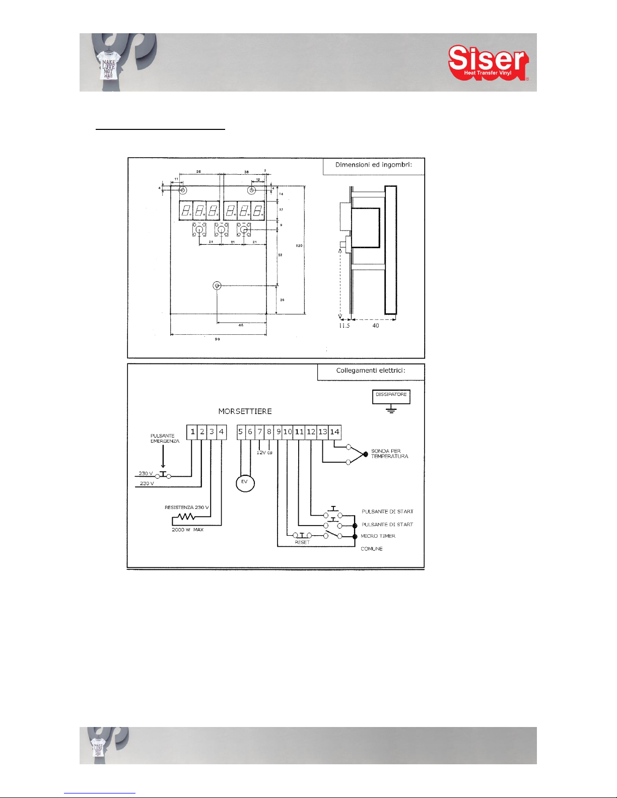
14. Electronic Diagram board S2
This manual is the property of SISER S.r.l., any even partial reproduction is forbidden
Mod. PRD 22 rev.2 - last updating: 01/2015
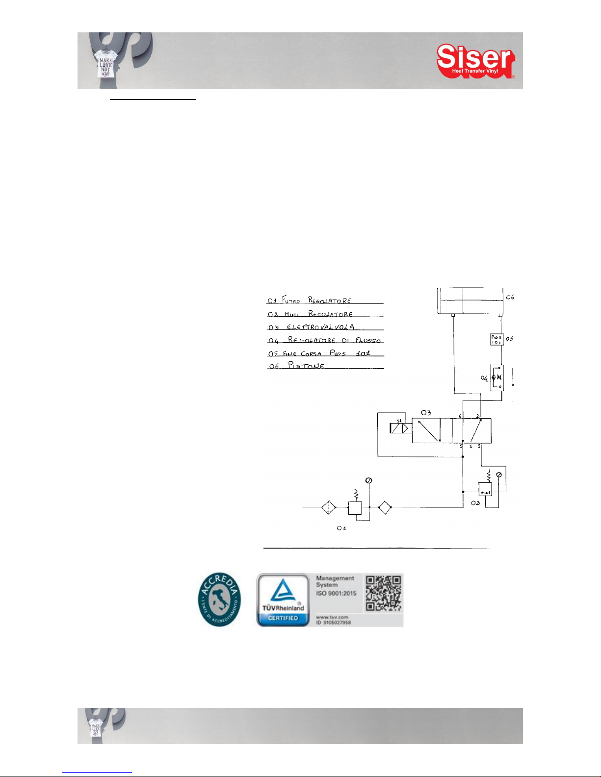
14. Pneumatic Diagram
1. filter controller
2. mini controller
3. electronic valve
4. control of air flow
5. end of piston run (PWS 101)
6. piston
Table of contents
Other Siser Power Tools manuals


