SISTEM AIR AUTO Jet TURBIX User manual

Technical manual
Manuel technique
Manual técnico
Technisches Handbuch
www.sistemair.com
MANUALE TECNICO
F
D
CENTRAL VACUUM SYSTEMS ByTecnoplus s.r.l.
EN
ES
V 1.0.0


19/04/2018 Rev:2.0.0 3
•
Type: separators with automatic unloading
• Model: AUTO Jet
• Revision 1.0.0
Line INSTRUCTION MANUAL
CENTRAL VACUUMSYSTEMS ByTecnoplus s.r.l.
1 USING THE MANUAL 4
2 TECHNICAL FEATURES 5
3 CONSTRUCTION FEATURES 6
4 SAFETY FEATURES 8
4.1 Safety symbols 9
4.2 Declaration of the absence of harmful substances 9
4.3 Safety measures regarding xed guards 9
4.4 Safety measures regarding movable guards 8
5 INTENDED USE OF THE MACHINE 10
6 UNINTENDED USE OF THE MACHINE 10
7 EQUIPMENT AND ACCESSORIES 11
8 INSTALLATION 12
8.1 Positioning 12
8.2 Fixing 12
8.3 Reversibility 13
8.4 Tube network connection 14
8.5 Compressed air network connection 15
8.6 Electrical connection 16
8.7 Application examples 17
9 CONTROL PANEL 18
10 COMMISSIONING AND USE 19
11 MAINTENANCE AND END OF LIFE 19
11.1 Intervention criteria 19
11.3 End of life 19
12 WARRANTY 20
13 DECLARATION OF CONFORMITY 21
INDEX

Auto Jet Instruction Manual
419/04/2018 Rev:2.0.0
CENTRAL VACUUMSYSTEMS ByTecnoplus s.r.l.
GENERAL INFORMATION
1. USING THE MANUAL
The instruction manual is a document written by the manufacturer and is an integral part of the central
vacuum unit. In the event that it is resold, given or rented to others, it must be handed to the new user
or owner.
It is recommended to use it and store it carefully during its entire service life.
The main objective of this manual is to indicate the correct use of the equipment, so that the best per-
formance is obtained, while keeping it in perfect working order and safe condition.
No part of this document may be reproduced, copied or disclosed by any means without the written
permission of TECNOPLUS s.r.l. owner of the SISTEM AIR brand. The TECNOPLUS company s.r.l.
reserves the right to make improvements or modifications to this manual and to this device at any time,
without the obligation to give prior notice to third parties.
To obtain the best results, the use of original SISTEM AIR consumables is recommended
The SISTEM AIR trademark mentioned in this manual is a registered trademark and belongs to to the
owner TECNOPLUS S.r.l.

5
2
19/04/2018 Rev:2.0.0
English
2- TECHNICAL FEATURES
B
C
D
E
F
G
H
A
Separators with automatic unloading
Template
Auto Jet
TURBIX
Article
7010.3
Control panel YES
Degree of protection IP 44
Supply V ac 230
Absorption A 1,5
Container capacity l 76
Pneumatic actuator pressure Bar 6
Dust entry mm 80
Blowing motor exhaust outlet mm 80
Pressurized air inlet G 3/4”
Nozzle pressure Bar 6 ÷10
Maximum number of recommended operators
2
Weight kg 105
Size A mm 740
Size B mm 740
Size C mm 370
Size D mm 253
Size E mm 182
Size F mm 165
Size G mm 153
Size H mm 1760

Auto Jet Instruction Manual
619/04/2018 Rev:2.0.0
CENTRAL VACUUMSYSTEMS ByTecnoplus s.r.l.
Suction module
connection
Stainless steel
cyclone cone
Stainless steel cylinder
dust collection
Nozzle solenoid
valve
Nozzle manifold
Dust entrance
connection
Electric control panel
Pressure regulator
pneumatic actuator
Load bearing frame
Exhaust pipe Ø 153 mm
Pneumatic actuator
Compressed
air nozzles
Aperture with gasket
3 - CONSTRUCTION FEATURES

7
2
19/04/2018 Rev:2.0.0
English
Dust separators for industrial use can be used in countless applications, thanks to their versatility and
compatibility with the other components of a centralized industrial vacuum system.
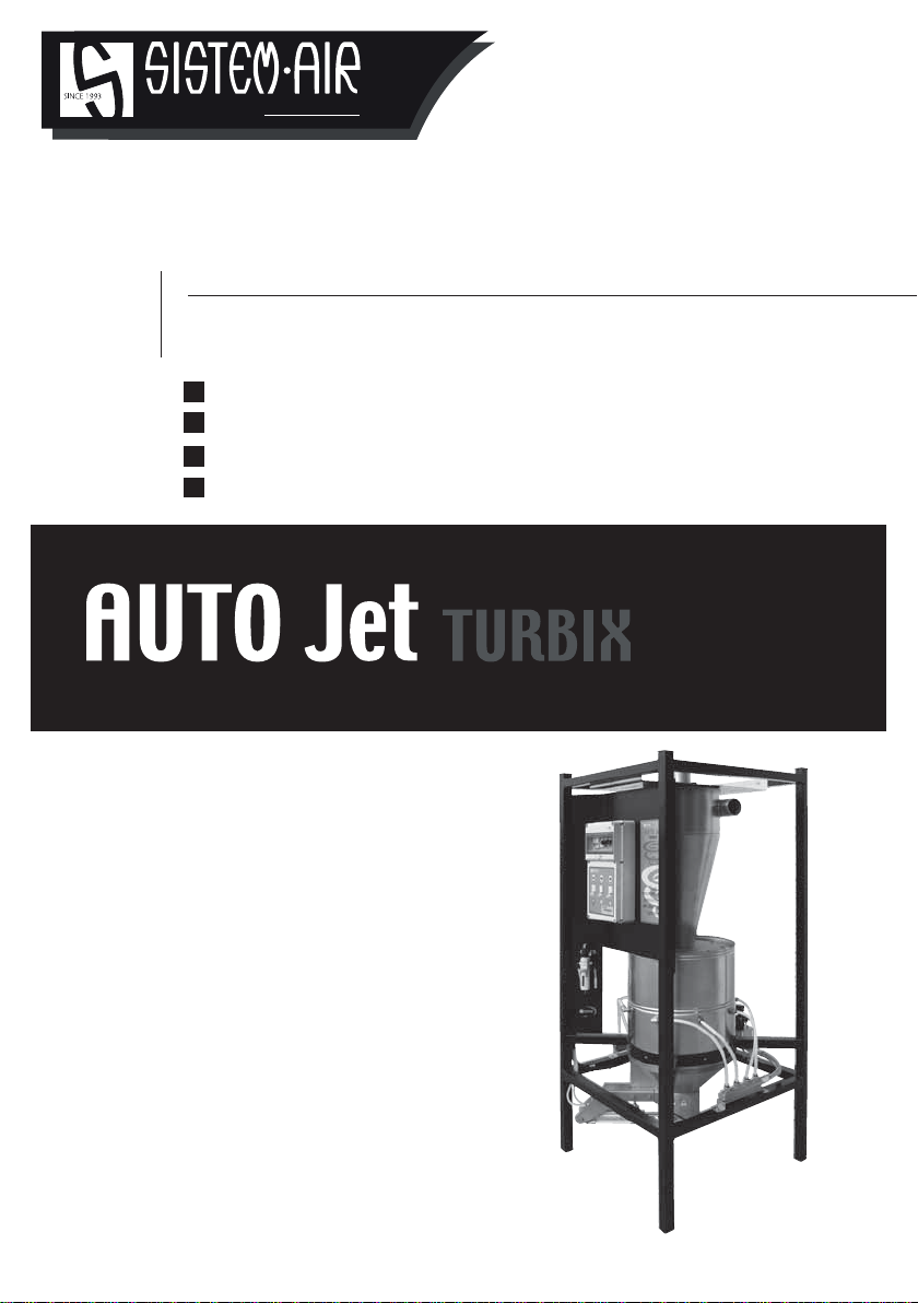
In particular, the special Auto Jet Turbix separator is a unique product of its kind: the presence of the
cone with cyclonic effect allows it to have an extraordinary ability to eliminate dust, preventing it from
clogging the central vacuum unit filter, while the automatic exhaust device makes it suitable for the as-
piration of large volumes of material without needing continuous emptying of the collection vessel. The
presence of the nozzles that discharge compressed air into the collection cylinder represent a further
advantage in the automatic emptying, making the separator suitable for use even in the case of aspira-
tion of very light and voluminous materials.
The AUTO Jet separator has been designed and constructed according to the criteria imposed by cur-
rent regulations and the community directives, without neglecting fundamental elements such as func-
tionality and practicality of use.
The main technical characteristics can be listed as follows:
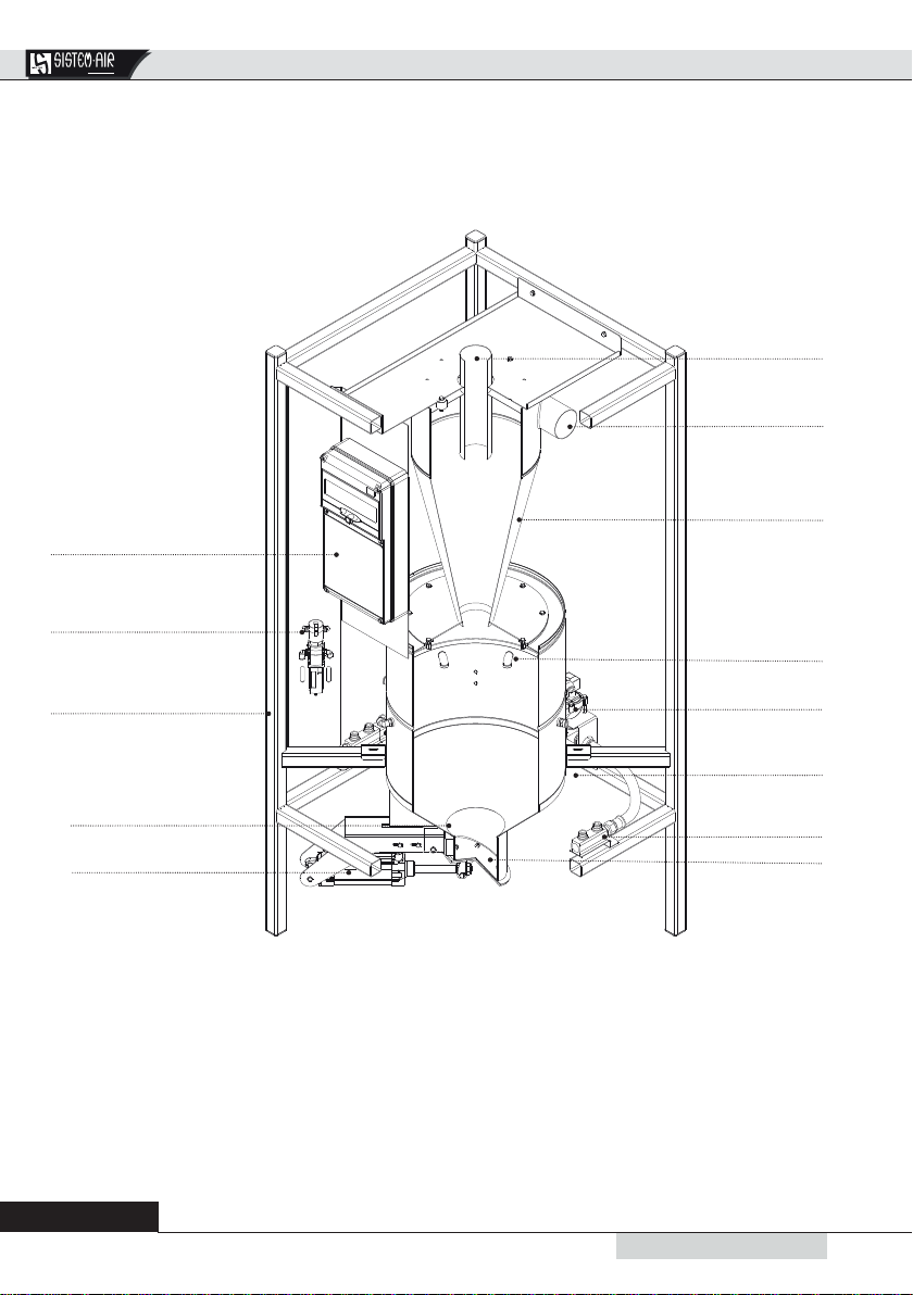
• Load bearing structure in epoxy powder coated steel
• Cylindrical shell in AISI 304 stainless steel
• Pneumatic linear actuator
• Possibility to connect 8 compressed air nozzles
• Control panel for the blowing, powder filling and dust discharge systems.
The pneumatic actuator allows the opening of the discharge door even in the presence of strong
depressions inside the separator, in order to allow the discharge of the material in any situation.
To facilitate the discharge of any type of collected material, even the lightest and most voluminous ones,
the separator is equipped with 8 nozzles that allow the discharge of compressed air when the lower
door is opened.
The shape of the cone allows the cyclonic separation of the collected material to be carried out,
guaranteeing a great effectiveness in eliminating dust, even fine ones, withoutusing a filter. Maintenance
will also be greatly reduced on the plant filter.
Rotating the material inlet fitting through 360 °, it is possible to rotate the inlet of the collected material by
unscrewing the fixing screws of the cone with predefined progressive angles of 45 ° each.
The separator with automatic drain is made of stainless steel: this material makes it suitable for the
aspiration of liquids, but also of incandescent particles. By accurately adjusting the timing of the
discharge, in case of entry of liquid and solid materials during the same suction cycle, it is possible to
avoid the formation of wet sediments which then solidify, becoming difficult to dispose of.

Auto Jet Instruction Manual
819/04/2018 Rev:2.0.0
CENTRAL VACUUMSYSTEMS ByTecnoplus s.r.l.
4 - SAFETY FEATURES
It is recommended to read carefully all of the instructions relative to installation, use and maintenance
contained in this manual.
Moreover, the following WARNINGS must always be followed:
•In case of maintenance:
- disconnect the appliance from electrical power supply
- close the AUTO Jet compressed air system
- discharge the pressurized air present in the AUTO JET system
• Do not use the appliance for improper use.
• Do not allow children to approach the equipment
• This appliance must not be used by persons (including children) with reduced intellectual, sensory
or mental abilities, or by persons without experience and knowledge, unless they are supervised, or
instructed to use the appliance by persons responsible for their safety.
• Wear protective gloves and a mask to perform maintenance work,
• Use only original spare parts
Finally, remember that pictograms or signs of danger and prohibition are found in the parts of the equip-
ment where, if you do not comply with the conditions dictated by the warnings, you can certainly create
unsafe situations.
WARNINGS: TECNOPLUS S.R.L. declines any form of responsibility or warranty if the purchaser or for
those who make changes or modifications to the product purchased, albeit minimal.
The equipment thus designed and manufactured is able to satisfy the current needs of the centralized
household suction market regarding both quality and application.
All materials and components used for its construction meet the CE safety standards and the certifi-
cates are held at the offices of TECNOPLUS S.R.L.
Finally, through the three potentiometers on the control panel it is possible to adjust the following
operating parameters:
- suction timing (to avoid excessive filling of container)
- aperture opening timing (to be set according to the specific weight and consistency of the vacuumed
material)
- compressed air jet timing which operate in emptying phase
Using the TEST button it is possible to test these three settings immediately, in order to find the optimal
settings based on the type of vacuumed materials.

9
2
19/04/2018 Rev:2.0.0
English
4.2 Declaration of the absence of harmful substances
TECNOPLUS S.r.l. declares that its products and equipment are made with materials that comply with
the limits established by current health and environmental protection regulations and do not contain
substances classified as SVHC (Substance of Very High Concern) in accordance with EC regulation
1907 / 2006 (REACH, ie registration, evaluation, authorization of chemical substances; Registration,
Evaluation, Authorization and Restriction of Chemical substances). Even if the aforesaid substances
are not used in the processing cycles of the raw materials and our products, their presence can not be
excluded in the order of p.p.m. (parts per million), due to micro-pollution of raw materials.
4.3 Safety related to xed closure guards
Access to the electrical parts is protected by a cover removable only by means of special equipment.
Each intervention on the equipment must be performed by qualified operators and with disconnection
of the electrical power supply.
4.4 Safety relating to movable closure guards
There are no movable closure guards, each enclosure is considered as a fixed enclosure, secured by
special screws. TECNOPLUS s.r.l. remind users that it is strictly forbidden to replace the screws used in
the design and construction of the machines, with others of different characteristics.
TECNOPLUS s.r.l. will immediately suspend the product warranty in case of any tampering by the
Customer.
We remind you to pay full attention to pictograms and warnings of danger or prohibition that
are located on various parts of the product: if not respected, it is possible to create unsafe
situations.
DANGER OF ELECTRICITY OR ELECTRICAL CURRENT
Danger of serious personal injury.
During maintenance operations, disconnect the power supply and ensure that the
power supply cannot be restored.
DANGER OF CUTTING
Danger of serious personal injury.
During maintenance operations, disconnect the power supply and ensure that
the power supply cannot be restored.
DANGER OF AUTOMATIC START
Danger of serious personal injury.
During maintenance operations, disconnect the power supply and ensure that the
power supply cannot be restored.
4.1 Safety symbols

Auto Jet Instruction Manual
10 19/04/2018 Rev:2.0.0
CENTRAL VACUUMSYSTEMS ByTecnoplus s.r.l.
6 - UNINTENDED USE OF THE MACHINE
It is extremely important NOT to use the appliance for the following uses, deemed incorrect and
dangerous:
•It must not be used to vacuum heavy, incandescent or liquid materials unless previously noti-
fied to the Manufacturer.
Furthermore the appliance is not designed to be used in explosive hazard environments, therefore:
• It is forbidden to vacuum materials with a high risk of explosion (gunpowder) or materials that are in-
dividually inert but which, once they have been vacuumed and mixed in the dust collection container,
can cause dangerous chemical reactions.
• It is absolutely forbidden to use the equipment in explosive atmospheres or outside the standard tem-
perature, pressure and humidity values.
•Do not vacuum any material that could cause electrostatic charges inside the tubing if not pre-
viously communicated to the Manufacturer.
Uses other than those indicated above are not allowed.
Any adaptation or modification of the product in order to make it suitable for vacuuming a par-
ticular type of material must be approved in writing by the manufacturer.
Any use other than that for which the product was built represents an anomalous condition that
can cause damage to the unit and constitute a serious danger for the user.
5 - INTENDED USE OF THE MACHINE
The AUTO Jet Turbix must strictly be connected to the system network and accordingly to a fine
dust separator, as it is not to be considered as a separator, but as a pre-separator. Incorrect connection
can generate blockages and breakdown of the central vacuum unit.
Installation of the AUTO Jet Turbix is recommended in environments where large amounts of powder
suction, particularly fine powder is required
When continuous use of the suction system is expected, powders can be discharged and collected in
containers of various kinds and sizes, without necessitating turning off the vacuum system.
When using the system to vacuum liquids, it is advisable to consult Sistem Air, in order to make the right
adjustments so as not to compromise the functionality of the motor unit.
The AUTO Jet Turbix must be used in combination with one or more blower motors with systems
configured for air flows up to 400 m3 / h.
These components are used for plants with the following characteristics:
- Ø 63/80 mm upright column
- Dust inlet Ø 80 mm
- Possibility of using the system simultaneously with up to 2 operators advised.
OPERATORS Ø flexible tube 32 OPERATORS Ø flexible tube 40
cccc ccc

11
2
19/04/2018 Rev:2.0.0
English
7 - KIT AND ACCESSORIES
The sales package of the plant also includes the accessories kit, comprised of the following elements:
1) N°1 AUTO Jet
2) N°2 rubber sleeves for connection to the suction tube network
3) N°4 metal clamps for fixing the sleeves
4) N°1 installation, use and maintenance manual
23
4
MANUALE TECNICO
www.sistemair.it
Domestic
1

Auto Jet Instruction Manual
12 19/04/2018 Rev:2.0.0
CENTRAL VACUUMSYSTEMS ByTecnoplus s.r.l.
8 - INSTALLATION
- CAUTION -
THESE OPERATIONS MUST BE PERFORMED
BY QUALIFIED PERSONNEL
It is the responsibility of the installer to check the risks present in the area where the product is
installed and to determine its suitability in compliance with the current legal regulations and with
the characteristics of the product described in this manual.
The installer must also comply with the provisions of this manual, as well as inform the user on the
operation and maintenance of the installed products, and report any hazards related to their use.
It is essential to leave adequate free space around the product to enable access in case of inspection,
repair and maintenance.
The product must not be exposed to atmospheric elements and must not be installed in areas subject
to: high humidity, possible flooding, or high temperatures.
The AUTO Jet Turbix separator can be installed in service rooms or in service areas protected from
bad weather, humidity and excessive temperature changes (working room temperature “-5 ÷ 45 ° C”,
relative humidity 20 ÷ 85% without condensation or freezing) .
8.1 Positioning
In order to allow correct use of the machine and easy maintenance, it is advisable to keep at least 60cm
free space on all four sides.
Allow the necessary space to facilitate the opening of the material discharge door, positioned in
the lower part of the AUTO Jet.
8.2 Mounting
The separator does not require special fixing.
However, it is necessary to make sure that the selected installation area has the following minimum
requirements for correct and safe positioning:
- a solid, perfectly level and horizontal supporting surface;
- a surface which is not subjected to vibration.
Moreover, it is also essential that there are no disconnections/irregularities which make the separator
unstable.

13
2
19/04/2018 Rev:2.0.0
English
1 2
8.3 Reversibility
The AUTO Jet is designed to be able to position the dust inlet fitting according to installation needs.
Unscrewing the 2 upper screws, fixing to the frame plate, and the 8 lower screws, fixing to the cylinder,
it is possible to rotate the inlet of the sucked material with pre-defined 45 ° progressive angles each.

Auto Jet Instruction Manual
14 19/04/2018 Rev:2.0.0
CENTRAL VACUUMSYSTEMS ByTecnoplus s.r.l.
8.4 Connection of the tube network
Connect the separator to the pipe
network of air intake, using the
sleeve and the metal
clamps supplied.
Connect, using the sleeve and the
supplied metal clamps, the AUTO
JET separator to a dust separator
with filter cartridge
The sizing of the suction unit and of the suction lines leading to theAuto Jet Turbix must be made giving
consideration to the number of simultaneous users and the type of material to be vacuumed.
N.B. It is advisable to position AUTO Jet as close as possible to the Industrial Motor to avoid power loss due
to tube network length and the use of connecting bends and branches.
The Sistem Air Technical Office is available for consultancy and / or estimates.
At the installa-
tion network
Tubing
Suction motor unit
AUTO Jet
Example of connection of the AUTO Jet separator:
Dust separator
with filter cartridge

15
2
19/04/2018 Rev:2.0.0
English
8.5 Connection of the compressed air network
Compressed air
connection G 3/4 “
Connection of compressed air system:
Connect the compressed air system to the G 3/4 “fitting located on the back of the AUTO Jet system.
It is always advisable to apply the maximum available pressure to the system, always respecting the
limits indicated, so as to be able to have the greatest flow rate on the nozzles, in order to assure their
correct operation.
Install a tap for closing the compressed air and a drain valve for the safe maintenance of the
appliance.
Pressure regulation applied to pneumatic actuator:
Before starting the AUTO Jet system, check that the pressure applied to the pneumatic actuator is
between 6 - 10 bar.
Never exceed the maximum pressure of 10 bar to avoid damaging the actuator itself.
In case the pressure is incorrect, adjust the regulator filter located on the front panel.
Regulator filter
pneumatic
actuator
- CAUTION -
NEVER APPLY PRESSURE OVER
10 BAR OR LOWER THAN 6 BAR

Auto Jet Instruction Manual
16 19/04/2018 Rev:2.0.0
CENTRAL VACUUMSYSTEMS ByTecnoplus s.r.l.
8.6 Electrical connection
X1
Electrical control panel
Open the front cover of the control panel to gain access to the terminal block for the electrical connec-
tions.
230VAC 50/60Hz
Suction outlets / Inlet
Suction start contact (MICRO)
central suction unit / Central vacuum
The complete schematic diagram is present inside the control panel.

17
2
19/04/2018 Rev:2.0.0
English
Liquids
The Turbix Auto Jet separator can be installed in
such a way as to allow the discharge of the vacu-
umed liquids where it is most suited to production
cycles:
- in drains,
- in dedicated tanks
- in cisterns.
It is advisable to contact the Technical Office to
best manage the use of this product with liquids.
8.7 Application examples
Solid residues / powders
The self-supporting frame can be raised or fixed
to other structures to allow the positioning of the
separator on top of trolleys, Big Bags or other col-
lection systems. In this way the handling and any
recovery of the vacuumed materials is facilitated.

Auto Jet Instruction Manual
18 19/04/2018 Rev:2.0.0
CENTRAL VACUUMSYSTEMS ByTecnoplus s.r.l.
9 - CONTROL PANEL
- + - + - +
TEST
Main Switch
Network presence
warning light
Vacuum line sockets
isolator
Nozzle test button and
pneumatic actuator
RED
potentiometer
GREEN
Potentiometer
BLUE
potentiometer
Main switch: magnetotherrmic switch for isolatiing and protecting the power supply line of the control
panel.
Warning light : if on, indicates the presence of power supply at the control panel.
Vacuum line isolator: switch to isolate the suction activation command in case of maintenance.
TEST button: by pressing this button it is possible to manually force a material discharge cycle, thus
checking that the AUTO Jet system is working correctly.
RED Potentiometer: adjustment of the maximum interval time between one discharge and the next
one. In this way it is possible to automatically force the discharge of the material without stopping the
suction.
Adjustment time: 5 to 225 seconds
GREEN Potentiometer: regulation of door opening time to allow complete emptying of collected mate-
rial inside the AUTO Jet separator.
Adjustment time: 5 to 225 seconds
BLUE potentiometer: adjustment of nozzle blowing time to facilitate complete emptying of collected
material inside the AUTO Jet separator.
N.B. The door opening time (RED potentiometer) has priority over the nozzle blowing time.
Adjustment time: 0 ÷ 225 seconds

19
2
19/04/2018 Rev:2.0.0
English
11.2 End of life
Disposal of the packaging, the accessories and the appliance must be carried out according to local reg-
ulations, ensuring the recycling of the raw materials from which they are made.
11 - MAINTENANCE AND END OF LIFE
11.1 Intervention criteria
It is absolutely forbidden to intervene on the product for repairs and / or maintenance not expressly au-
thorized in this manual.
All repairs for faults or malfunctions must be performed by qualified service personnel.
In case of interventions by unauthorized personnel, any warranty on the product becomes void and re-
lieves the manufacturer from any liability for any damage to persons and / or property resulting from such
intervention.
Before putting the AUTO Jet system into service, make sure that the tubing system is correctly and
securely fixed to it, that the electrical and compressed air connections have been made according to the
law, as well as the systems to which it is connected, and that the pressure in the circuit complies with
the limits indicated in chapter 8.5
Set up a vacuum cycle to check its operation, then before vacuuming the selected material, check that
there are no foreign bodies inside.
Verify that everything indicated in chapter 8 has been done correctly.
Set the main switch and the isolating switch to 1.
Set the adjustment of the 3 potentiometers on the control panel, see chapter 9.
Carry out some loading and unloading cycles of the material to verify that the settings are correct.
It is advisable never to exceed the level of the nozzles positioned in the dust collection cylinder
of the AUTO Jet system, in order to facilitate the operation of unloading the material.
Once the AUTO Jet system is operating: further adjustment of the potentiometer could be necessary if
the specific weight or type of material to be vacuumed is changed, even marginally.
In such cases it is sufficient to recalibrate the loading time, so that it is adequate to fill the loading
cylinder of the AUTO Jet system at each cycle.
In cases where the AUTO Jet system will be inoperative for an extended period, turn the main switch to
0, switch off the power supply, close the compressed air tap and discharge the AUTO Jet pressurized
air system.
10 COMMISSIONING AND USE

Auto Jet Instruction Manual
20 19/04/2018 Rev:2.0.0
CENTRAL VACUUMSYSTEMS ByTecnoplus s.r.l.
12 WARRANTY
PRODUCT LIMITED WARRANTY CONDITIONS
The Manufacturer guarantees to the original purchaser the absence of defects in material
and workmanship of the product for the period stated, from the date of purchase. Except as
prohibited by applicable law, this warranty is non transferable and it is limited to the
original purchaser. The present warranty gives the buyer specific legal rights and the possibility
to claim rights which can vary under local laws.
Read all warnings and instructions before using the product purchased.
The entire liability of the manufacturer and your exclusive remedy for any breach of warranty
will be at the discretion of the Manufacturer:
(1) To repair or replace the product, or (2) refund the purchase price, provided that the product
has been returned to the point of purchase, or such other place as may be specified by the
manufacturer, with a copy of the sales receipt or detailed and dated receipt. The shipping and
handling are not free of charge, except in cases where this is prohibited by applicable law.
To repair and replace the product, the manufacturer may, at their own discretion, use new,
refurbished or used parts in good working condition.Any replacement product will be warranted
for the remaining time of the original warranty period, or for any period of time that complies
with the provisions of the current law.
This warranty does not cover problems or damage resulting from (1) accident, abuse,
misapplication, repair, alteration or unauthorized disassembly; (2) maintenance operation, use
which is not in accordance with the product instructions or connection to an improper voltage
supply; or (3) use of consumables and spare parts which are not supplied by the manufacturer
or authorized service center.
Valid warranty claims are generally processed through the point of purchase of the product.
Please agree this detail with the retailer where you purchased the product.
The Warranty claims that cannot be processed through the point of purchase, as well as any
other product related questions, should be addressed directly to the manufacturer. Addresses
and contact information for customer support can be found at the internet address
www.sistemair.com
Except as stated by relevant laws in force, any implied warranty or condition of
merchantability or suitability for a particular purpose relating to this product is limited to the
duration of the Limited Warranty period for the specific product purchased.
Some jurisdictions do not allow limitations on the duration of implied warranties or the exclusion
or limitation of incidental or consequential damages, so the above limitation may not apply to
you. This warranty gives you specific legal rights and you may have other rights that vary from
state to state, or from jurisdiction to jurisdiction.
Consumers have legal rights under applicable national legislation governing the sale of
consumer products. Such rights are not affected by the warranties in this Limited Warranty.
No dealer, agent, or employee of the manufacturer is authorized to make any modification,
extension or addition to this warranty.
Table of contents