SKE SKR800W Product guide

SKE RADAR SKR800W
Manual Book(Ver: 1.0)

2
Catalogue
1. Warranty and service scope of radar level sensor............................................................................... 3
2. Unpacking inspection and precautions........................................................................................................ 3
2.1 Unpacking inspection............................................................................................................................... 3
2.2 Precautions .............................................................................................................................................. 4
3. Storage and transportation.......................................................................................................................... 4
3.1 Storage conditions ................................................................................................................................... 4
3.2 Transport the product to the measuring place........................................................................................ 4
4. Product introduction.................................................................................................................................... 5
4.1 Product Overview .................................................................................................................................... 5
4.2 Technical parameters............................................................................................................................... 6
4.3 Application............................................................................................................................................... 6
4.3.1 Measured medium....................................................................................................................... 6
4.3.2 Ambient temperature of radar level sensor ................................................................................ 6
4.3.3 Protection grade .......................................................................................................................... 6
5. Outline structure of radar level sensor........................................................................................................ 7
5.1 Outline structure diagram........................................................................................................................ 7
6. Terminal block of radar level sensor ............................................................................................................ 7
7. Description of radar commissioning parameters......................................................................................... 8
7.1 Radar level sensor mobile app main interface ........................................................................................ 8
7.2 Waveform interface ................................................................................................................................. 8
7.3 Radar menu ............................................................................................................................................. 9
7.3.1 User menu ................................................................................................................................... 9
7.3.2 Setting range and definition of basic parameters.................................................... 10
8. Radar installation and commissioning ....................................................................................................... 11
8.1 Preparations before installation ............................................................................................................ 11
8.2 Selection of radar installation position.................................................................................................. 11
8.3 Software configuration description ....................................................................................................... 12
9. Maintenance and repair ............................................................................................................................ 15
10. Trouble Shooting........................................................................................................................................ 16

3
1. Warranty and service scope of radar level sensor
The warranty period of the radar level sensor is one year from the date of delivery,
and the warranty period of repair and maintenance is half a year. This warranty is
only limited to the users of the original buyer or the designated dealer, and does
not apply to users who use it wrongly for human reasons, transform, neglect or damage
it due to accidents and abnormal use.
For the faulty radar level sensor returned within the scope of warranty, free
maintenance is provided. To obtain warranty service, please contact the after-sales
service department and attach the fault description. With the permission of our company,
send the radar sensor to the after-sales service department.
If the radar level sensor has expired the warranty period or it is confirmed that the
failure is caused by misuse, modification, negligence, accident and abnormal
conditions, the maintenance cost budget will be provided according to the relevant
maintenance charge standard, and the maintenance will be carried out after it is
approved. After the radar level sensor is repaired, it is sent back to the customer,
and the customer needs to pay the maintenance and transportation costs. (Attachment:
warranty)
2. Unpacking inspection and precautions
2.1 Unpacking inspection
Instruction manual
Certificate of conformity
Packing list
Radar Level Sensor
Check the name, model and other contents on the nameplate

4
Check whether the radar sensor housing is intact and observe
Check the random items against the packing list
Check whether the specifications, models and accessories are correct and complete
according to the packing list of the radar level sensor. If there is any problem,
please contact the customer service center in time for replacement.
2.2 Precautions
Please read this manual before installing the radar level sensor.
Modifications due to product upgrading are subject to change without notice. Please
refer to the real object.
3. Storage and transportation
3.1 Storage conditions
Temperature:–40~+60 ℃
Use the original packaging
3.2 Transport the product to the measuring place
Use the original packaging to transport the radar sensor to the measuring place
Collision, dampness and chemical erosion shall be prevented during
transportation and storage

5
4. Product introduction
4.1 Product Overview
76-81ghz frequency modulated continuous wave (FMCW) radar products (also known as
millimeter wave radar) adopt the millimeter wave band with higher frequency than Ku
band radar. They have important applications in long-range target detection,
long-range imaging, multispectral imaging in strong smoke and dust environment, and
can detect smaller targets than microwave radar and achieve more accurate positioning,
with higher resolution and stronger confidentiality.
As a 78GHz band radar used in the field of industrial measurement, high-precision,
non-contact level and liquid level measurement has incomparable advantages over other
ordinary microwave pulse radars and guided wave radars. With extremely narrow beam
and penetration ability, it can better adapt to ultra complex working conditions
without weakening the measurement performance.

6
4.2 Technical parameters
Radar Level
Two wire system
Max range
8m、15m
Error
±1‰FS、±2‰FS、±5‰FS
Migration
±9.9m
Signal output
4~20mA/Modbus
Power supply
DC 24V ( 22V~30V )
Ambient temperature
-20℃~+70℃
Ambient humidity
(0%~95%)RH
Protection
IP67
Display
Mobile Phone APP
Weight
0.35kgs
Sizes
ϕ
76mm×107mm
4.3 Application
4.3.1Measured medium
In general, the dielectric constant of the measured medium is required to be greater
than 2, so that it can have a good reflection cross section
4.3.2Ambient temperature of radar level sensor
The ambient temperature range of radar level sensor is: -20 ℃~ +70 ℃.I n areas with
strong sunlight, it is recommended to install the instrument in a cool place or use
a sunshade, which can not only avoid the excessive temperature in the instrument caused
by exposure to the sun, but also provide good ventilation and heat dissipation.
4.3.3Protection grade
Waterproof and dustproof grade: IP67

7
5. Outline structure of radar level sensor
5.1 Outline structure diagram
Diagram1
P1 diagram for sizes
6. Terminal block of radar level sensor
The radar level ga sensor leads out two power lines, the red one is connected to the
positive pole of the power supply, and the blue one is connected to the negative pole of
the power supply.
Interface description
Lead wire
Explain
red(+)
DC24V Positive of power supply
blue (-)
DC24V Negative of power supply
8
7. Description of radar commissioning parameters
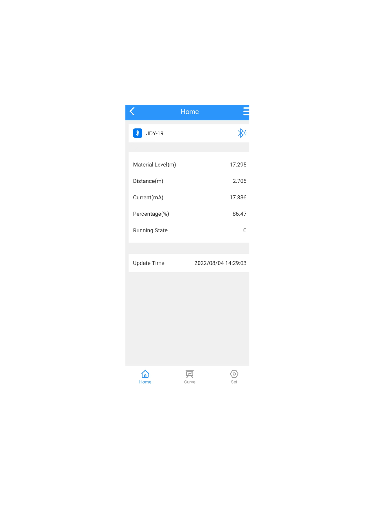
7.1 Radar level sensor mobile app main interface
P2 APP main interface
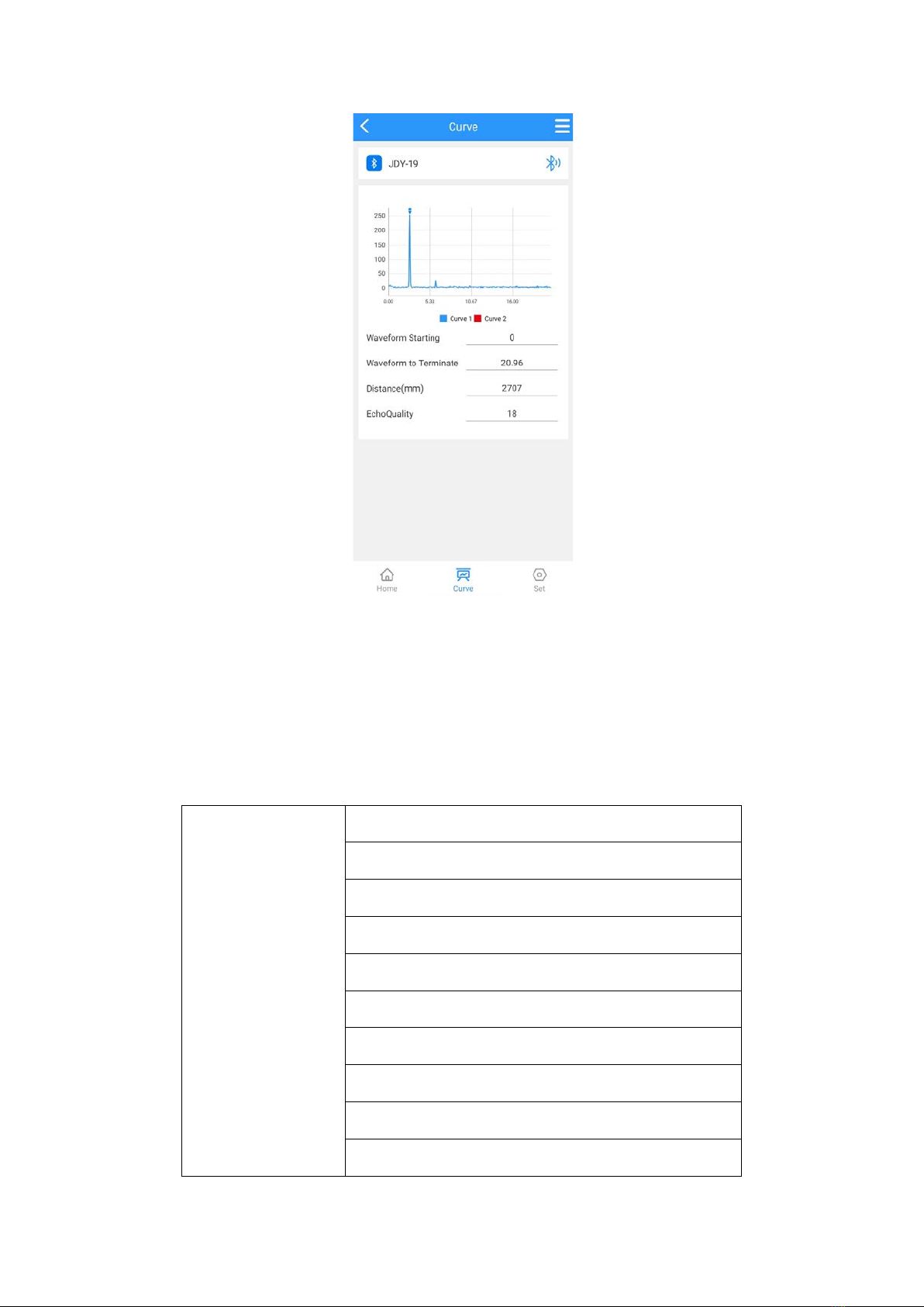
7.2 Waveform interface
9
P3 waveform interface
7.3 Radar menu
7.3.1User menu
Basic parameters
Measure range
Migration
4mA position
20mA position
Blind zone
Damping time
Device address
Baud rate
Backups
Restore

10
7.3.2 Setting range and definition of basic parameters
Basic settings:
Range(500~50000)mm:It depends on the working condition; Indicates the longest
distance that the level sensor can measure.
Migration(-9999~9999)mm:It depends on the specific working conditions
4mA Position:4mA Level corresponding to current output,Unit mm
20mA Position:20mA Level corresponding to current output,Unit mm
Blind zone:The range is 200mm to the measuring range, which is set according
to the specific working conditions
Display type:level value / space distance value
Damping time:In order to improve the stability of the measured output value,
a larger [damping time] can be set to achieve the stability of the measured value
and increase the anti-interference ability. For example, when the damping time
is 10, the measured object level changes step at time t, and the measured output
value follows the actual position of the measured object after 10 seconds.
Device address:During RS-485 communication, the slave address is the local
address (value range: 1-99, default value: 1).
Baud rate:The baud rate of this device during RS-485 communication is 9600
by default.
Backup user parameters:
After the working parameters are backed up, if you forget the original working
parameters after manually modifying the parameters, you can "restore" them in
the basic settings.
Restore user parameters:
Used to restore the backed up user parameters.

11
8. Radar installation and commissioning
8.1 Preparations before installation
Understand the installation location, structure, measuring range
Required tools: DC 24V power supply, etc
After the tools are ready, unpack the products and check the packing list to
determine whether the materials are complete.
8.2 Selection of radar installation position
Avoid installing the instrument in the center or close to the edge of the container, otherwise it is likely to produce
wrong readings.
P4 installation position
Avoid false echo diagram
P5 False echo

12
ladder and grid container treatment
P6 Ladder and Grid container
Wall hanging and grid container treatment
P7Wall hanging and Grid container
8.3 Software configuration description
Instrument connection
Connect the power line to the DC 24V terminal of the instrument; Pay attention
to the positive and negative poles, and do not connect them reversely.
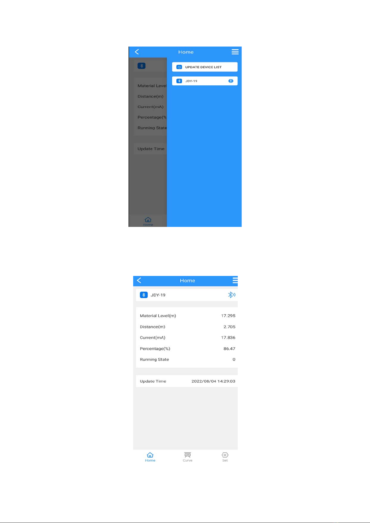
Set instrument parameters
Open the mobile app to display the device connection interface. As shown in the
following figure:
13
P8
Directly click the device name to be set to enter the main interface, as shown
in the following figure.
P9

14
Click the "curve" or "setting" button at the bottom of the screen to enter the
echo curve interface and parameter setting interface respectively. Click the
"setting" button here to enter the parameter setting interface, as shown in the
following figure.
P10
Click "basic parameters" to enter the basic setting interface. As shown in the
following figure.
P11

15
Set the "range" according to the working condition, directly click the following
digital input box to modify, and the other parameters are modified in the same
way. After the parameters are modified, you need to click the "set" button to
set it before it takes effect. You can click the "read" button to refresh the
parameters.
4mA position and 20mA position must be within the range. The relationship between 4mA
position, 20mA position and range is shown in the following figure:
P12
As shown in the figure, when the level is lower than 4mA, the main interface displays the
level of 0, and when the level is higher than 20mA, the main interface displays the level
value of 20mA.
9. Maintenance and repair
Pay attention to keeping the radar sensor clean, and try to be waterproof,
moisture-proof, corrosion-proof, and avoid being violently collided and hit by other
objects
Avoid direct sunlight on the main body of the radar sensor, keep away from heat
sources and pay attention to ventilation. If the ambient temperature exceeds the rated
temperature, corresponding cooling protection measures should be taken.
When the ambient temperature is too low, the instrument protection box or other
protective devices can be used for antifreeze protection, and pay attention to keeping
the radar dry.
16
Radar sensor should be detected regularly. (the detection cycle is determined
by the user according to the specific situation)
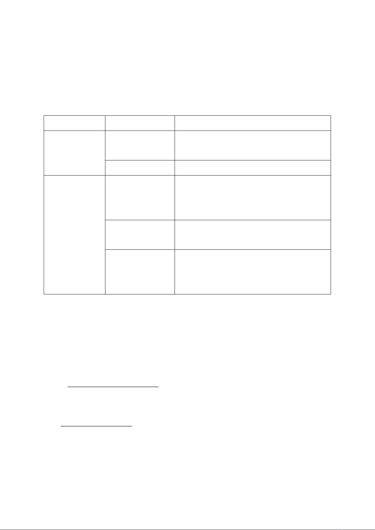
10. Trouble Shooting
Trouble Cause Solution
No display
Power supply
error
Check whether the DC 24V voltage and
current meet the requirements.
Wiring error Check whether the wiring is correct.
Unstable
indication
Too much
fluctuation
Change the installation position of the
radar or reduce the fluctuation of the
object to be measured.
Weak echo
Try angle calibration or rotate the radar
installation position.
Strong
electromagnetic
interference
Ground or shield the radar sensor.
Shaanxi ShengKe Electronic Technology Co., Ltd
Website: http://www.skgauge.com
Tel: 029-88858601 Fax: 029-88858601
E-mail: jilina@skgauge.com
Postcode: 710065
Address: Room 1911. Fazhan 25 Road, High-Tech Zone Xi’an City, Shaanxi China
Table of contents
Popular Radar manuals by other brands

Decatur Electronics
Decatur Electronics Genesis VP Directional user manual

NorthStar
NorthStar Ethernet Radar install guide

Emerson
Emerson 3308A Rosemount 3308 Series Reference manual

Endress+Hauser
Endress+Hauser Levelflex FMP51 Brief operating instructions

Motorline professional
Motorline professional MR30 User's and installer's manual

Emerson
Emerson Rosemount 5300 Series Reference manual

CognitiveTPG
CognitiveTPG CPRR user manual

Blickfeld
Blickfeld Qb2 Quick start manual

Decatur Electronics
Decatur Electronics Surface Velocity Radar SVR2-01 user manual

Bindicator
Bindicator TDR-1000 quick start guide

Endress+Hauser
Endress+Hauser micropilot S FMR 533 operating instructions

Saab
Saab TankRadar PRO user guide


