SKETCHNBUILD SNB-PX24 User manual
SNB-PX24 25” PLANER
MANUAL

SNB-PX24 PLANER MANUAL
2
6/2016
CONTENTS
1. TECHNOLOGY PARAMETER AND SPECIFICATION INDEX...………………….….3
2. OPERATION AND SAFETY…………………….……………………..……………………….…4
3. ELECTRICAL CONFIGURATION……………………………………….……………………….5
4. OILING SYSTEM.…………………………………………………………………….………….…...5
5. OPERATION…………………………………………………………….…………………….………..7
6. ADJUSTMENT ……………………………………………….……………………………..………...7
7. TESTING …………………………………………………………………………………………………10
8. ACCESSORY & PARTS LIST………………………………………………………………….……10
CAUTION: Read these instructions carefully before turning on the machine.

SNB-PX24 PLANER MANUAL
3
6/2016
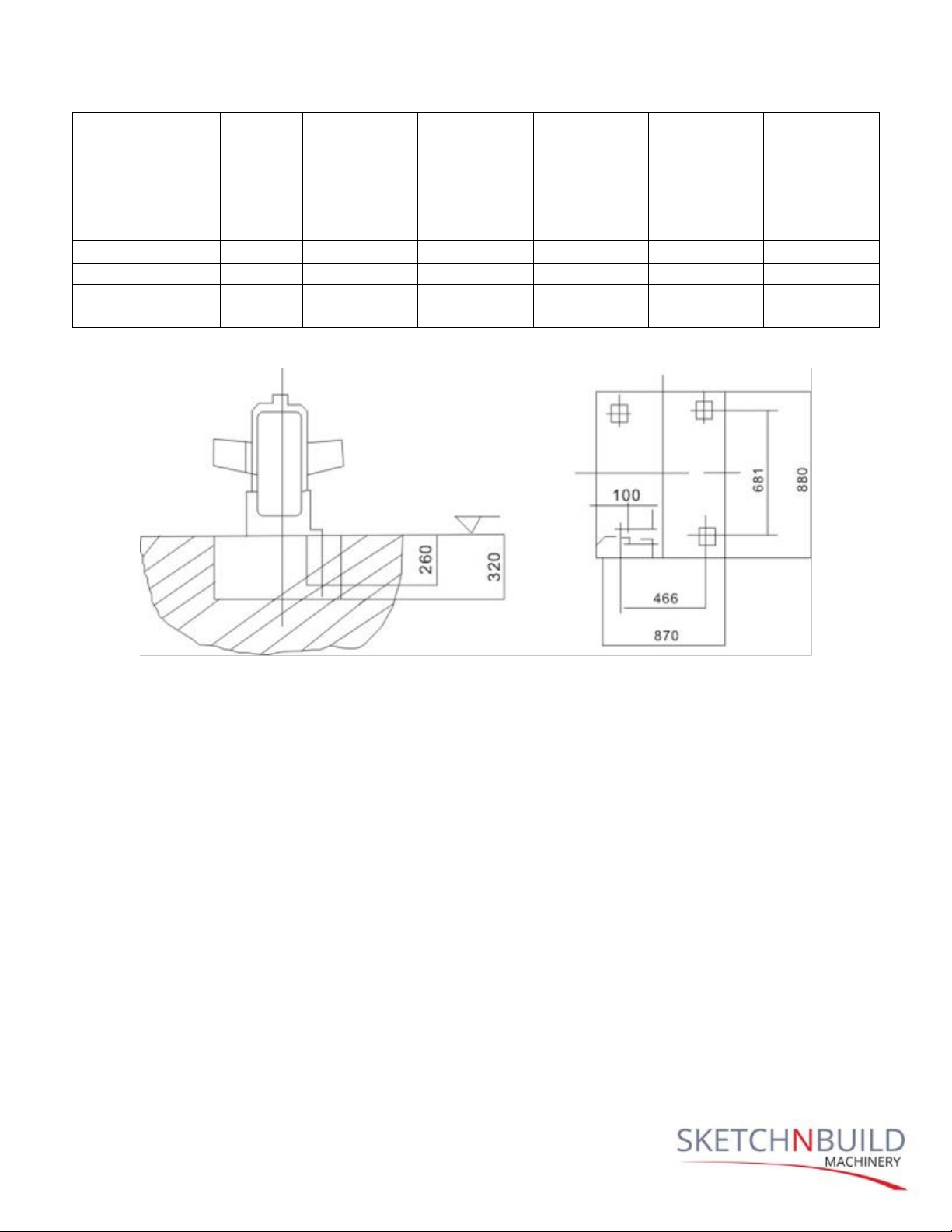
1. PARAMETER AND SPECIFICATION INDEX
No.
Parameter
SNB-PX24
Specification
1
Max working width
24”/600mm
2
Max working
thickness
8”/200mm
3
Min working length
8”/200mm
4
Max cutting depth
0.2”/5mm
5
Cutter head speed
5000r/min
6
Feeding speed
6.5-9m/min
7
Spindle motor
5HP/7.5kw
8
Equipment weight
1168lbs/530kg
NOTE: The above design and specifications might differ on each machine model.
Please refer to the actual machine.

SNB-PX24 PLANER MANUAL
4
6/2016
2. OPERATION AND SAFETY
1. Keep doors closed and all the tools and adjustment wrenches away from the work
table before operation.
2. Be sure all parts are securely tightened and oil relevant parts before operation.
3. TURN DOWN the triangle belt of motor by hand to ensure the shaft of blade, gear
work well and without collision.
4. STOP the planer immediately once there is abnormal sound and do not start it
without finding out the reason.
5. SAFETY OF OPERATOR AND EQUIPMENT, keep the planer power-off when doing any
adjustments, maintenance and cleaning.
6. KEEP PLANER IN A DRY COOL WORKING ENVIRONMENT and do not operate under
direct sunlight or outside in wet rainy conditions.
7. CHANGE THE BLADE when it is worn or after using for a period of time. And make
sure to change all blades at the same time to keep the same weight for each blade,
otherwise, high speed imbalance will shorten the accuracy and planer’s operating
time.
8. KEEP CHILDREN, VISITORS and PETS AWAY. All non-operating personnel should keep
a safe distance from working equipment to avoid any accident or injury.
9. 9、KEEP WORK AREA AND PLANER CLEAN AFTER USE. Switch off the power after use
every day.
10. CHANGE OR REPAIR BROKEN PARTS. DO NOT OPERATE MACHINE WITH FAULTY
PARTS, to avoid machine malfunction and injury to user.
11. KEEP THE MAX CUTTING WORKING AREA DEPTH less than 0.2” (5 mm). 0.2” (5 mm)
for less than 8” (200mm) of lumber width, O.O78” (2 mm) for more than 16” (400
mm) of lumber width) to prevent part damage or overheating.
12. SWITCH OFF PLANER for inspection to prevent damage to the motor or relevant
parts such as the blades or bolts from over loading under the following situations:
A.The shaft of blade slows down or cannot move because of cutting over depth or
there is an obstruction on the workpiece from a nail or screw.
B. There is abnormal sound.
RESTART PLANER once problem is resolved.
SNB-PX24 PLANER MANUAL
5
6/2016
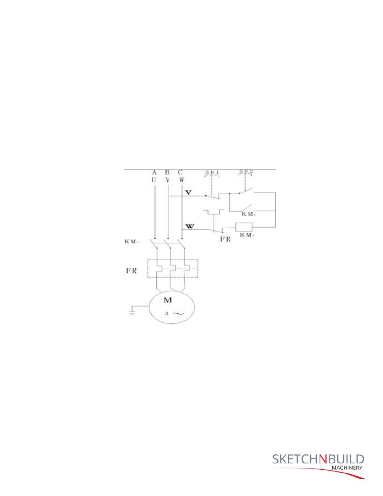
3. ELECTRICAL CONFIGURATION
The motor is controlled by a magneto-electricity starter. This provides the advantages
of a simplified connection, easy operation and over load prevention. In the graphic
below, electric principle A, connecter will be looped when the start button is pulled, and
then the loop will be locked as the power gets through the connecter to make the
motor run. The relay FR will work and make KMI lose press when the motor is under
over loading and KMI will switch off.
NOTE: The wiring for this planer is four-core cable. Please make sure the earth
installation is safe before setting.
4. OILING SYSTEM
The planer should be oiled by hand regularly to extend the working life, maintain a smooth
operation, as well as improve the working efficiency., Oiling should be done on relevant
parts with minimal oil to avoid oil run over which wastes oil and damages other parts. Refer
to oiling instructions below:

SNB-PX24 PLANER MANUAL
6
6/2016
Oiling Instructions
No
Area
Oiling Part
Drops of
Oil
Oiling
instruction
Type of Oil
Oiling Time
1
Motor
Bearing
2
Take the front
cover apart and
remove the
cover of motor
CAS#3
Every 6
months
2
Lever on work
table
Worm gear
2
Take apart and
oil
CAS#3
Every 6
months
3
Lever on work
table
screw
2
Direct
Engine oil
Per week
4
Lever on work
table
Chain&
chain wheel
2
Direct
Engine oil
Per shift
5
Lever on work
table
Lever path
4
Direct
Engine oil
Per shift
6
Hand wheel
fastening
Oil cup
1
Direct
Engine oil
Per shift
7
Holding roller
work table
Bearing
4
Direct
Cas#3
Every 6
months
8
Shaft of planning
blade
Bearing
2
Direct
Cas#3
Per month
9
Delivery roller
Bearing
2
Take the end
cover apart
Cas#3
Every 6
months
10
Press roller
Bearing
2
Take the end
cover apart
Cas#3
Every 6
months
11
Drive system of
delivery and
press roller
Skew gear
5
Direct
Cas#3
Per shift

SNB-PX24 PLANER MANUAL
7
6/2016
12
Drive system of
delivery and
press roller
bearing
5
Take the end
cover apart
Cas#3
Every 6
months
13
Gear box
gear
2
Take the end
cover apart
Cas#3
Every 6
months
14
Gera box
Bearing
4
Take the end
cover apart
Cas#3
Every 6
months
15
Gear box
Chain&
chain wheel
2
Direct
Engine oil
2 times per
shift
5. OPERATION
The motor is shared by the blade shaft, delivery and press roller. These mechanisms work
together once the Start button is pressed. Otherwise, the planer will stop when the Stop
button is pulled. The lever on work table works when the hand wheel is turned manually.
Release the fastener at the back of hand wheel when turning it to position the work table
then lock the fastener to keep the wheel position and make the work piece the same width.
Both rollers to the left and right sides of the breaker installed on top of planer use the same
setting as cutting the work piece a second time.
6. ADJUSTMENT
1. Up and down adjustment.
Before adjusting the position of work table, first release the fastener at the back of
hand wheel, and then turn the hand wheel left to adjust the work table. Fasten the
fastener to maintain position and to make the work piece the same width. When
adjusting, should check the index on work table position the scale on the gauge base.
This shows the thickness of the finished work piece in relation to the thickness of work
piece. Finally fasten the fastener after performing a cutting test and inspecting the
work piece. The thickness of most work pieces will be the same after performing the
above steps.
2. Sharpening and changing of planer blade should be done on worn blades which is
or after using for a period of time.
Use the steps below to change the blades:
SNB-PX24 PLANER MANUAL
8
6/2016
1) Lift the breaker, and use the wrenches to loosen the bolt on the pressing strip, take out
the blade for sharpening or changing
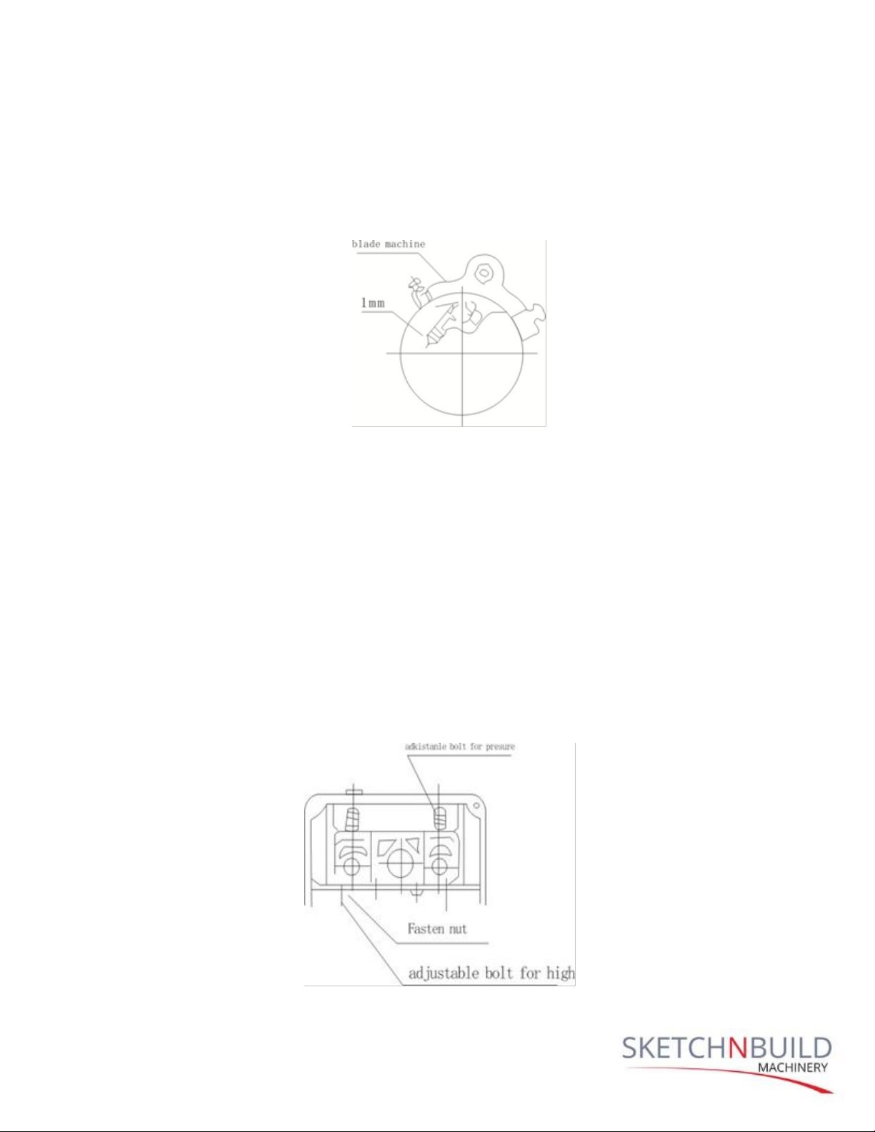
2) Setting and adjustment of planer blade:
a) Make sure both ends of blade machine are even and fixed, and then adjust four
adjustable bolts to keep them in the same position (1mm more or less).(Graph B)
Graph B
b) Put two springs into the 2 hold ¢at the bottom of blade groove.
c) Insert the planer blade and pressing strip to the blade groove. The elasticity of the
two springs will make the blade and blade edge spring to the arc surface of the
blade machine. Tighten the fastening bolt of pressing strip.
d) Set one blade at a time, whilst keep all blades in the same position. Finally inspect
the fastening of all bolts of pressing strip to avoid the blades from getting loose and
causing damage.
3) Adjustment for bearing pressure of press roller
The pressure of spring on top of bearing of the pressing roller is adjusted at the factory.
The user can adjust by turning the left or right wheel to tighten or loosen. The left-hand
threaded nut tightens the spring, whereas the right-hand threaded nut loosens the
spring (Graph C)
Graph C

SNB-PX24 PLANER MANUAL
9
6/2016
4) Up and down adjustment for delivery roller and press roller.
The positions of the bearing of the delivery roller and press roller have been factory
adjusted. If bearings to the right or left become uneven, the user can loosen the four
fastening nuts under the bearing so that outer diameter of the delivery roller and press
roller are positioned over the blade shaft by about 1mm. Tighten the four fastening
nuts after adjustment (Graph D).
Graph D
5) Up and down adjustment of the holding roller on work table:
a) The Up and Down adjustment for the holding roller on work table has been factory
adjusted. The user can loosen the four fastening nuts under the work table for
readjustment. Revolve those four adjustable nuts to position the outer diameter of
the holding roller over the table by about 0.01~0.2mm. Tighten the four fastening
nuts after adjustment (Graph D-above).
b) Maintaining a parallel line between work table and blade shaft:
The work table and blade shaft adjusted to be parallel to each other. The user can
loosen the two fastening bolts at the pedestal for readjustment. Revolve the
pedestal screw left or right to move the table up or down, then tighten the fastening
bolts after adjustment.
6) Up and down adjustment (for blade shaft) of breaker and press roller:
The up and down adjustment for blade shaft by breaker and press roller have been factory
adjusted. The user can adjust the position of two adjustable bolts to the left and right sides
of the breaker for readjustment.
Additionally, adjust the position of the two adjustable bolts positioned to the left and right
side of the press roller then continue to follow instructions below:

SNB-PX24 PLANER MANUAL
10
6/2016
Loosen the fastening bolts, and revolve the transfer bolt to align to the bottom of the
breaker and back press machine just above the cutting circle of blade shaft (about 0.5mm,
then tighten the fastening bolts after adjustment.
7. TESTING
1. Adjust all parts and fasten all fixtures, paying special attention attention bolts on the
pressing strip to ensure blades are properly secured and prevent personal injury or
damage to machine.
2. Ensure everything is running smoothly, and no abnormal sounds and or collision
before start the planer. Inspect the turning direction of trigonal belt from the side of
motor to see whether the blade shaft is turning left with the delivery roller and press
roller turning right. If not switch of the planer and change the electrical connection of
the motor.
3. Remove all tools, gauges and wrenches from the work table to avoid them from
rolling into the machine to avoid personal injury and damage to the machine.
4. Stop the planer for inspection when there is an abnormal sound and collision. Check
all parts to ensure that they are securely fastened. Do not restart the planer before
resolving the problem to prevent damage.
8. ACCESSORY & PARTS LIST
Accessory List
Name
Specification
Quantity
Equipment
Planer
1
Triangle belt
900
1
Dust hood
1
Manual
1

SNB-PX24 PLANER MANUAL
11
6/2016
Parts List
Part
Code #
Dimension
Name
Precision
grade
Quantity
Remark
Blade shaft
360
30x70x19
Single redial
ball bearing
E
2
Delivery &Press
Roller
204
20x47x14
Single radial
ball bearing
4
Holding roller on
work table
61004
20x40x12
Single radial
ball bearing
with
dustproof
cover
4
Lift wheel box on
working table
8200
10x26x11
Single thrust
bearing
2
Principal Axis
Gear
80106
30x55x13
Single radial
ball bearing
with
dustproof
cover
1
Gear box
105
25x47x12
Single radial
ball bearing
with
dustproof
cover
4
Copper gear
8004
20x42x12
Single radial
ball bearing
with
dustproof
cover
2
Triangle belt
70105
25x47x12
Single radial
ball bearing
with
dustproof
2
SNB-PX24 PLANER MANUAL
12
6/2016
cover
Tension wheel
80201
12x32x10
Single radial
ball bearing
with
dustproof
cover
2
Motor box
1803
Triangle belt
3
Gear box
1397
Triangle belt
1
Gear box
1041
Triangle belt
1
990(preparati
on)
Table of contents


