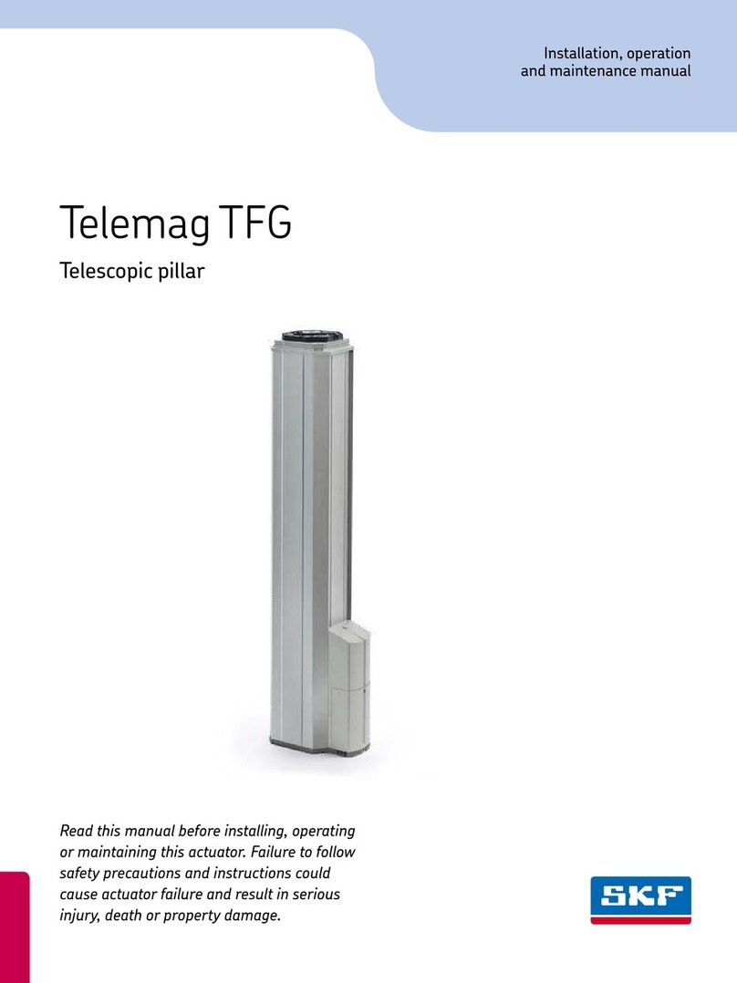
SKF CPMT1 S Series User manual

CPMT
Telescopic pillar
WARNING: Read this manual before installing, operating or
maintaining this telescopic pillar. Failure to follow safety pre-
cautions and instructions could cause telescopic pillar failure
and result in serious injury, death or property damage. Keep
this manual nearby for future reference.
Installation, operation
and maintenance manual
www.lmotion.ru

Contents
Contents
1 General information.............................3
1.1 Information in this manual .....................3
1.2 Explanation of symbols and signal words...........3
1.3 Limitation of liability ..........................4
1.4 Copyright...................................4
1.5 Spare parts .................................5
1.6 Warranty terms ..............................5
1.7 Customer service.............................5
2 Safety ........................................6
2.1 Use .......................................6
2.2 Responsibility of the owner and processor..........7
2.3 Personnel requirements .......................8
2.4 Specific dangers .............................9
2.5 Safety equipment ............................9
2.6 Safeguard against restart .....................11
2.7 Modifications of device .......................11
2.8 Manufacturer’s declaration of EMC compliance .....12
3 Technical data ................................16
3.1 Ambient conditions ..........................16
3.2 Product label ...............................16
4 Structure and function..........................18
4.1 Overview ..................................18
4.2 Brief description ............................19
4.3 Requirements for third party control units (mandatory in
medical applications).........................22
4.4 Connections ...............................23
4.5 Operating elements..........................24
4.6 Options ...................................24
4.7 Accessories ................................25
5 Transport, packaging and storage ................26
5.1 Safety information for transportation ............26
5.2 Transport inspection .........................26
5.3 Return to the manufacturer....................27
5.4 Packaging .................................27
5.5 Storage ...................................28
6 Installation and first operation ...................29
6.1 Installation location ..........................30
6.2 Inspections prior to first operation...............30
6.3 Installation ................................31
6.4 Connection to the control unit ..................34
6.5 Connection to operating element................36
6.6 Connection to power supply. . . . . . . . . . . . . . . . . . . .36
7 Operation ....................................37
7.1 Safety ....................................37
7.2 Turn on ...................................38
7.3 Turn off ...................................38
7.4 Actions before use ...........................38
7.5 Actions during operation ......................39
7.6 Emergency disengagement ....................40
8 Maintenance ..................................41
8.1 Maintenance plan ...........................42
8.2 Maintenance work...........................43
8.3 Measures following completed maintenance .......45
9 Malfunctions..................................46
9.1 Malfunction table............................48
9.2 Start of operation after malfunction repair ........49
10 Dismantling .................................50
10.1 Dismantling...............................51
10.2 Disposal .................................51
11 Appendix ....................................52
11.1 Technical data .............................52
11.2 Plans and diagrams.........................53
11.3 Approved accessories .......................57
11.4 Declaration of incorporation ..................57
2
2
www.lmotion.ru

1 General information
1.1 Information in this manual
This manual provides important information on how to work with
the telescopic pillar (also called the device) safely and efficiently. The
manual is part of the device, must always be kept near the device
and should be available for personnel to read at any time. All person-
nel working with the device must read and understand this manual
before starting any work. Strict compliance with all specified safety
notes and instructions is a basic requirement.
Moreover, the accident prevention guidelines and general safety
regulations applicable at the place of use of the device must also be
complied with.
For better representation of circumstances, the illustrations in this
manual are not necessarily to scale and may vary from the actual
design of the device.
All information and notes in this manual were compiled with due
consideration given to applicable standards and regulations, the
present status of technology and our years of knowledge and
experience.
1.2 Explanation of symbols and
signal words
Safety precautions
Safety precautions are identified by symbols and signal words
defined on the right side of this page. These signal words indicate
the severity of the hazard. Adhere to these safety precautions and
take caution in order to avoid accidents that may result in personal
injury or damage to property.
!Note!
Describes useful hints and
recommendations as well as information
for efficient and trouble-free operation.
Is used to indicate a dangerous situation,
which can lead to serious personal injury
or death, if the precautionary measures
are ignored.
WARNING
Is used to indicate a dangerous situation,
which can lead to minor or moderate
injury, if the precautionary measures are
ignored.
CAUTION
Is used to indicate a dangerous situation,
which will lead to death or serious injury,
if the precautionary measures are
ignored.
DANGER
3
www.lmotion.ru

General information
1.3 Limitation of liability
All information and notes in this manual were compiled under due
consideration of valid standards and regulations, the present state of
technology and our years of experience.
The manufacturer will not be liable for injury or damage resulting
from:
•disregarding this manual
•unintended use
•employment of untrained personnel
•unauthorized conversions
•unauthorized technical modifications
•manipulation or removal of the screws on the device
Where the telescopic pillar has been customized by SKF, the actual
product delivered may be different from what is described in this
manual. In this case, ask SKF for any additional instructions or safety
precautions relevant to this product.
We reserve the right to make technical modifications to the tel-
escopic pillar to improve usability.
1.4 Copyright
This manual is protected by copyright law and to be used exclusively
by SKF customers for internal purposes.
Passing this manual on to third parties, duplication of any kind –
even in the form of excerpts – as well as the use and/or disclosure of
the contents without the written consent of the manufacturer, is not
permitted, except for internal purposes.
Violation of SKF’s copyright may become the subject of a future
claim for damages.
4
www.lmotion.ru

1.5 Spare parts
This telescopic pillar is designed to be repairable. Repairs must only
be carried out by persons authorized by the manufacturer. All war-
ranty and service claims become void without notice, if any screws
on the telescopic pillar have been manipulated.
If the device cannot be repaired on site by authorised personnel,
it must be dismantled from the application and sent to the
manufacturer.
1.6 Warranty terms
The applicable and effective warranty terms are those contained in
the manufacturer’s terms and conditions of sale contained in the
SKF sales contract that governs this sale.
1.7 Customer service
SKF Customer Service is always available to provide technical infor-
mation and to answer questions.
The contact information for SKF Customer Service can be found
on www.skf.com.
Safety hazard caused by wrong spare parts
Wrong or faulty spare parts can adversely affect safety and
cause damage, malfunctions or total failure.
Therefore, follow the precautions below:
•Use only genuine spare parts from the manufacturer.
•Spare parts in/on the device may only be replaced by the
manufacturer.
WARNING
5
www.lmotion.ru

Safety
2 Safety
2.1 Use
2.1.1 Intended use
The device has been designed and built exclusively for its intended
purpose as described in these instructions. The device is to be used
only for dynamic centric compression or tensile-loaded lift of a load.
It is intended for interior use only.
The device has been designed for the movement of medical
equipment, specifically medical procedure chairs and tables.
2.1.1.1 Product service life
The telescopic pillar CPMT is designed for a service life of 10 years in
a typical medical procedure equipment application.
Product service life of the telescopic pillar CPMT depends on the
stroke and load of the application. According to the L10 lifetime of the
device, 56 000 cycles can be achieved in an average medical procedure
application (average load of 4000 N and average stroke of 150 mm)
Some reference values for different stroke and load conditions are
given in the table below.
Lifetime [cycles] reference at given average load and stroke
Average load Fm4 000 N 5 000 N 6 000 N
CPMT1-XS0XXXFX-000
Stroke = 150 mm 42 000 23 000 14 000
Stroke = 300 mm 21 000 11 000 7 000
Stroke = 500 mm 12 000 7 000 4 000
CPMT1-XM0XXXFX-000
Stroke = 150 mm 56 000 30 000 18 000
Stroke = 300 mm 28 000 15 000 9 000
Stroke = 500 mm 17 000 9 000 5 000
6
www.lmotion.ru

2.1.2 Unintended use
Any use other than the intended use, or modifications to the device
without the manufacturer’s written agreement, or operation beyond
the technical limits, is considered unauthorized.
Specific application exemptions are:
•Flammable anaesthetic mixture with air
•Flammable anaesthetic mixture with oxygen or nitrous oxide
•Increased radiation
•Places exposed to water (wet rooms)
2.1.3 Essential performance
The essential performance of the telescopic pillar CPMT is moving or
holding a load within the boundaries defined by the device specifica-
tions given in this operating manual and the datasheet.
2.2 Responsibility of the owner
and processor
The device is designed for use in commercial applications by its
owner or processor.
The processor is the contracting partner of the reseller or the
manufacturer. The processor installs the device in a complete system
(application).
The owner or processor of the system is therefore subject to the
requirements of the Occupational Health and Safety Act.
In addition to the safety instructions in this manual, the owner or
processor must do the following, concerning safety and accident
prevention guidelines and environmental protection regulations,
applicable to the site of the system’s installation:
•Inform themselves of applicable industrial safety regulations.
They must also determine additional hazards that arise due to the
specific working conditions prevailing at the site where the device
is installed, using risk assessment. The risk assessment must be
implemented in the form of work instructions for device
operation.
•Confirm that the work instructions created for the system, includ-
ing the device, satisfy current legal requirements, and if not, alter
the instructions accordingly.
•Clearly regulate and specify the responsibilities for installation,
operation, maintenance, and cleaning.
•Ensure that all employees who deal with the device have read and
understood this manual.
!Note!
Any unauthorized use of the device can cause personal
injury and property damage. Always adhere to the instructions
given in this manual.
7
www.lmotion.ru

Safety
•Provide personnel with the required protective equipment.
•Provide training for personnel at regular intervals and inform per-
sonnel of the hazards.
In addition, the owner or processors must ensure that the device is
in adequate working condition. They must do the following:
•Ensure that the maintenance intervals described in these instruc-
tions are complied with.
•Have all safety devices inspected regularly for function and
completeness.
2.3 Personnel requirements
2.3.1 Qualifications
The following qualifications are specified for different areas
of activity listed in this manual.
•An instructed person (operator): Instructed by the customer in
an orientation session on the assigned tasks and possible dangers
arising from improper behaviour.
•Qualified personnel: Based on their professional training, know-
how and experience, as well as knowledge of the applicable
standards and regulations, are able to independently perform
assigned work activities and to detect and avoid possible dangers.
•Professional electrician: Based on his/her professional training,
know-how and experience, as well as knowledge of the applicable
standards and regulations, is able to independently perform work
on electrical systems and to detect and avoid possible dangers.
In addition, the professional electrician has been trained for the
special location where he/she works and knows the relevant
standards and regulations.
Only persons who can be expected to perform their tasks reliably,
are permitted to work with this device. Persons whose reaction capa-
bilities are impaired, through the use of drugs, alcohol or medication
for example, are not permitted.
Improper installation, operation and maintenance can
result in serious injury, death or property damage.
Use only qualified, instructed or trained personnel (as described
below) who have read, understood and followed these
instructions.
WARNING
8
www.lmotion.ru

2.4 Specific dangers
The following section lists the residual risks that have been deter-
mined by a risk assessment.
•Heed the safety instructions listed here, and the warnings in sub-
sequent chapters of this manual, to reduce health hazards and to
avoid dangerous situations.
2.5 Safety equipment
Integration of an emergency-stop system (for certain
applications)
The device is intended only for installation into an application or
system. It does not have its own operating control elements, and
does not have an independent emergency-stop function. Therefore,
the device must be installed so that it is part of an emergency shut-
off system and can be stopped if necessary.
The emergency shut-off system must be connected in such a way
that any disruption of the power supply or reactivation of the power
supply after a power disruption, cannot cause a hazardous situation
for persons or objects.
The emergency shut-off system must always be freely accessible.
Danger of injury caused by moving components
Rotating and/or linearly moving components can cause serious
injury.
Therefore:
•Do not work on, or place, hands ,arms or any other parts of
the body, close to moving components.
WARNING
!Note!
The processor decides which applications require
installation of an emergency shut-off system.
9
www.lmotion.ru

Safety
Integration of a patient release system (for certain applications)
The device is intended only for installation into an application or sys-
tem. It does not have its own operating control elements, and does
not have an independent patient release mechanism. In the event of
a malfunction, the device cannot extend or retract.
If required by the application, a separate provision for patient
release must be installed, to allow safe release of the patient in case
of emergency, or equipment failure.
Integration of a safety mechanism to prevent unintended
triggering of the operating device (for certain applications)
The device does not have its own operating control elements, and
does not have a safety mechanism against unintended triggering of
the operating device.
If required by the application, a safety provision must be provided
to prevent unintended triggering of the operating device.
The following safety mechanisms have been installed:
•The telescopic pillar CPMT is fitted with a thermoswitch in the
motor, which switches off the telescopic pillar if the temperature
reaches a certain threshold, in order to reduce the risk of fire.
•Backup nuts are fitted on the ballscrews to prevent the pillar from
collapsing if there is a ballscrew failure.
•End limit switches are installed to provide a safe current cut-off
when the end of stroke position of the device is reached. In case of
failure of the end limit switches, a mechanical safety end-stop
prevents the device from exceeding its intended stroke.
!Note!
The processor decides whether the intended application
requires the installation of an emergency patient release
system.
!Note!
The processor decides whether the intended application
requires the installation of a safety mechanism to prevent unin-
tended triggering of the operating device.
10
www.lmotion.ru

2.6 Safeguard against restart
Protect CPMT against an unauthorised restart.
Pull the power-line plug of the control unit attached to the CPMT,
out of the power outlet.
2.7 Modifications of device
Life-threatening situation through unauthorized restart
For work in hazard zones, there is a risk that the power supply
could be turned on without prior authorization. This presents a
potentially life-threatening situation for people in the hazard zone.
•Read the information contained in this manual, concerning
safeguarding against any unintentional restart of the power
supply.
•Always follow the procedure as described below.
WARNING
To avoid hazardous situations and to ensure optimal perfor-
mance, do not make any changes or modifications to the device
unless they have been specifically authorized by SKF.
WARNING
11
www.lmotion.ru

Safety
2.8 Manufacturer’s declaration of
EMC compliance
IEC/EN 60601-1-2:2007 Medical Electrical Equipment
Part 1-2: General requirements for safety
Additional standard: Electromagnetic
compatibility-requirements and tests
Guidance and manufacturer’s declaration – electromagnetic emissions (Table 1 - IEC 60601-1-2)
The telescopic pillar CPMT is intended for use in the electromagnetic environment specified below. The customer or user of
the telescopic pillar should ensure that it is used in such an environment.
Emissions test Compliance Electromagnetic environment – guidance
RF emissions CISPR 11 Group 1 The telescopic pillar CPMT uses only RF energy for internal function.
Therefore, RF emissions are very low and not likely to cause any
interference with nearby electronic equipment.
RF emissions CISPR 11 Class B
Harmonic emissions
IEC 61000-3-2
Class A The telescopic pillar CPMT is suitable for use in all establishments,
including domestic establishments and those directly connected to
the public low-voltage power supply network that supplies buildings
used for domestic purposes.
Voltage fluctuations/
flicker emissions
IEC 61000-3-3 Complies
12
www.lmotion.ru

Guidance and manufacturer’s declaration – electromagnetic immunity (Table 2 - IEC 60601-1-2)
The telescopic pillar CPMT is intended for use in the electromagnetic environment specified below.
The customer or user of the telescopic pillar should ensure that it is used in such an environment.
Immunity test IEC 60601
test level
Compliance level Electromagnetic
environment – guidance
Electrostatic
discharge (ESD)
IEC 61000-4-2
± 6 kV contact
± 8 kV air
± 6 kV contact
± 8 kV air
Floors should be wood, concrete or
ceramic tile. If floors are covered with
synthetic material, the relative humidity
should be at least 30%.
Electrical fast
transient/burst
IEC 61000-4-4
± 2 kV for power
supply lines
± 1 kV for input/output
lines
± 2 kV for power
supply lines
± 1 kV for input/output
lines
Mains power quality should be that of
a typical commercial or hospital
environment.
Surge
IEC 61000-4-5
± 1 kV line(s) to
line(s)
± 2 kV line(s) to earth
± 1 kV differential mode
± 2 kV common mode
Mains power quality should be that of
a typical commercial or hospital
environment.
Voltage dips, short
interruptions and
voltage variations
on power supply
input lines
IEC 61000-4-11
<5% U1
(>95% dip in U1)
for 0,5 cycle
40% U1
(60% dip in U1)
for 5 cycles
70% U1
(30% dip in U1)
for 25 cycles
<5% U1
(>95% dip in U1)
for 5 s
<5% U1
(>95% dip in U1)
for 0,5 cycle
40% U1
(60% dip in U1)
for 5 cycles
70% U1
(30% dip in U1)
for 25 cycles
<5% U1
(>95% dip in U1)
for 5 s
Mains power quality should be that of a
typical commercial or hospital
environment. If the user of the
telescopic pillar CPMT requires
continued operation during power
mains interruptions, it is recommended
that telescopic pillar CPMT is powered
from an uninterruptible power supply or
a battery.
Power frequency
(50/60 Hz)
magnetic field
IEC 61000-4-8
3 A/m 3 A/m If distortion occurs, it may be necessary
to position the telescopic pillar CPMT
further from sources of power
frequency magnetic fields, or to install
magnetic shielding. The power
frequency magnetic field should be
measured in the intended installation
location to ensure that it is sufficiently
low.
Note: U1 is the a.c. mains voltage prior to application of the test level.
13
www.lmotion.ru

Safety
Guidance and manufacturer’s declaration – electromagnetic immunity (Table 4 - IEC 60601-1-2)
The telescopic pillar CPMT is intended for use in the electromagnetic environment specified below.
The customer or the user of telescopic pillar should ensure that it is used in such an environment.
Immunity test IEC 60601
test level
Compliance level Electromagnetic
environment – guidance
Conducted RF
IEC 61000-4-6
Radiated RF
IEC 61000-4-3
3 Vrms
150 kHz to 80 MHz
3 V/m
80 MHz to 2,5 GHz
3 Vrms
3 V/m
Portable and mobile RF
communications equipment should be
used no closer to any part of the
telescopic pillar CPMT, including cables,
than the recommended separation
distance calculated from the equation
applicable to the frequency of the
transmitter.
Recommended separation distance
d = 1,2 √P
d = 1,2 √P 80 MHz to 800 MHz
d = 2,3 √P 800 MHz to 2,5 GHz
where P is the maximum output power
rating of the transmitter in watts (W)
according to the transmitter
manufacturer and d is the
recommended separation distance in
meters (m). Field strengths from fixed
RF transmitters, as determined by an
electromagnetic site survey1), should be
less than the compliance level in each
frequency range2). Interference may
occur in the vicinity of equipment
marked with the following symbol:
Note 1: At 80 MHz and 800 MHz, the higher frequency range applies.
Note 2: These guidelines may not apply in all situations. Electromagnetic propagation is affected by absorption and reflection from structures, objects and people.
1) Field strengths from fixed transmitters, such as base stations for radio (cellular/cordless) telephones and land mobile radios, amateur radio, AM and FM radio
broadcast and TV broadcast cannot be predicted theoretically with accuracy. To assess the electromagnetic environment due to fixed RF transmitters, an
electromagnetic site survey should be considered. If the measured field strength in the location in which the telescopic pillar CPMT is used exceeds the applicable RF
compliance level above, the Model 006 should be observed to verify normal operation. If abnormal performance is observed, additional measures may be necessary,
such as re-orienting or relocating the telescopic pillar CPMT.
2) Over the frequency range 150 kHz to 80 MHz, field strengths should be less than 3 V/m.
14
www.lmotion.ru

Recommended separation distances between portable and mobile RF communications equipment and the
telescopic pillar CPMT (Table 6 – IEC 60601-1-2)
The telescopic pillar CPMT is intended for use in an electromagnetic environment in which radiated RF disturbances are
controlled. The customer or user of the telescopic pillar CPMT can help prevent electromagnetic interference by maintaining
a minimum distance between portable and mobile RF communications equipment (transmitters) and the telescopic pillar
CPMT as recommended below, according to the maximum output power of the communications equipment.
Rated maximum output
power of transmitter
[W]
Separation distance according to frequency of transmitter [m]
150 kHz to 80 MHz
d= 1,2 √P
80 MHz to 800 MHz
d= 1,2 √P
800 MHz to 2,5 GHz
d= 2,3 √P
0,01 0,1 0,1 0,2
0,1 0,4 0,4 0,7
1 1,2 1,2 2,3
10 3,8 3,8 7,3
100 12,0 12,0 23,0
15
www.lmotion.ru

Technical data
3 Technical data
3.1 Ambient conditions
Operation
•Indoor use only at: Operation
•Ambient temperature +10 to +40 °C.
•Atmospheric humidity max 90%
•Air pressure from 700 to 1 050 hPa
•Mains supply with overvoltage category I
•Pollution degree 2
Storage/transport
•Temperature –20 to +60 °C
•Atmospheric humidity from 0% to 90%, non-condensing
•Air pressure from 700 to 1 050 hPa
3.2 Product label
The type label (fig. 1 and fig. 2) is located on the outer tube and
contains the following information:
!Note!
The technical data (dimension, weight, output, connection
details etc.) can be found in the appendix.
Fig. 1
Position of
type label
Position of logo
16
www.lmotion.ru

Type label (without options):
1 Type designation
2 Manufacturer
3 Maximum current consumption
4 Serial number
5 Duty cycle of operation (ON/OFF time)
6 IP protection class
7 Indoor use only
8 CE mark
9 UL test mark
10 Recommendation to read operating manual
11 Disposal information
12 Date of manufacture (month, year)
13 Manufacturer’s address
14 Maximum stroke
15 Pull force
16 Push force
17 Voltage
Fig. 2
SKF Actuation System
CPMT1-1S0400F1-000 N0L012345678
24V–30V =
max.5000Npush max.4000Npull
SKF Actuation System (Liestal) AG, CH-4410 Liestal SWISS MADE
Bj:03.14
400mm IP20
12A Int. 1min/9min
13
24
5
6
7
12
13 8
10
11 9
i
CUS
17
16
15
14
17
www.lmotion.ru

Structure and function
4 Structure and function
4.1 Overview
a1 Outer tube base plate
a2 Motor cable
a3 Outer tube
a4 Middle tube
a5 Inner tube
a6 Rim covers
a7 Glide pads
a8 Inner tube base plate
a9 Mechanical safety end stop
a8
a5
a7
a6
a9
a2
a4
a3
a1
Fig. 3
18
www.lmotion.ru

Fig. 4
Base plate view
b1
b4
b1
b2
b3
b1
b1
b1
b1
b2
b2
b2
c1
c1
c2
c1
c1
c1
c1
Outer tube base plate
b1 Threads M10 for mounting screws
b2 Centering screws for plates on tube
b3 Attachment of ballscrew to base plates
b4 Hole on outer tube base plate – no function
c1 Areas of force distribution
c2 Areas of force distribution
Inner tube base plate
4.2 Brief description
The functional principle of the telescopic pillar CPMT is based on a
push or pull force for the movement of centric and eccentric loads.
The CPMT requires an external controller for it to be operational.
A DC gear motor attached to the middle tube drives two spindle
nuts simultaneously via a spur gear. The rotation of the nuts induces
a linear motion of the two ballscrews in opposing directions. The
ballscrews are attached to the base plates and cause an extension or
retraction of the telescopic tubes depending on the direction of
motion. A built-in brake holds the position at a standstill or during
power cut.
19
www.lmotion.ru

Structure and function
Outer tube base plate (a1)
The outer tube base plate has four holes to access attachment bores
in the outer tube (b1) for the mounting screws. This enables the pil-
lar to be fastened to one side of the application. The outer tube base
plate must be attached permanently with fastenings screws M10 to
a metal plate in the application, which has to support the areas of
force distribution (c1, c2).
Motor cable (a2)
The cable (a2) exits to one side at the outer tube base plate (a1) and
has to be connected to an external control unit via the DIN-8 plug or
the flying leads cable attached.
Outer tube (a3)
The outer tube is the tube with the largest outside dimensions. The
CPMT pillar can be mounted in any orientation to place the outer
tube (a3) at the top or bottom of the application.
Middle tube (a4)
The middle tube is the tube between the outer and inner tubes.
Inner tube (a5)
The inner tube is the tube with the smallest outside dimensions. The
CPMT pillar can be mounted in any orientation to place the inner
tube (a5) at the top or bottom of the application.
Rim covers (a6)
The purpose of the rim covers for the outer and middle tube is to
protect the tube guiding system from dust and to prevent the
ingress of foreign matter. The rim covers must not be removed
under any circumstances.
Glide pads (a7)
The purpose of the glide pads (a7) is to provide a stiff, virtually play-
free guiding of the tube sets.
Inner tube base plate (a8)
The inner tube base plate has four holes to access attachment bores
in the inner tube (b1) for the mounting screws. Its purpose is to fas-
ten the pillar to one side of the application. The inner tube base plate
must be attached permanently with fastenings screws M10 to a
metal plate in the application, which has to support the areas of
force distribution (c1, c2).
Mechanical safety end-stops (a9)
The purpose of the mechanical safety end-stops (a9) is to block the
extension of the tubes in the event of failure of the end limit
switches. This is a safety mechanism only.
Areas of force distribution (c1, c2)
The outer and inner tube base plates must be attached to a support
plate in the application. The areas of force distribution have to be
supported in the application by an adequately dimensioned support
20
www.lmotion.ru
This manual suits for next models
1
Table of contents
Other SKF Lifting System manuals
Popular Lifting System manuals by other brands

Extreme Max
Extreme Max Boat Lift Boss installation instructions

Omega Lift
Omega Lift 43000 Operating instructions & parts manual

Aqua Creek Products
Aqua Creek Products Scout Excel F-SCTXL manual

AMGO
AMGO HS-10 Installation and service manual

Blue Giant
Blue Giant U Series Installation & owner's manual

pewag
pewag VNMW owner's manual