twin busch TW 242 E User manual

TW 242 E
Basic-Line Lift
Electronic
INSTALLATION, OPERATION AND MAINTENANCE MANUAL
Always read the manual carefully to avoid damage or accidents through misuse.

TWIN BUSCH GmbH
Technical changes for purposes of a technical advancement as well as deviation in colour, errors and printing mistakes are reserved.
page 2 of 45
INDEX
1. Important warnings 4 - 5
1.1 Warnings
1.2 Qualified personnel
1.3 Safety warnings
1.4 Warnings
1.5 Noise level
1.6 Training
2. General overview 6-7
2.1 General description
2.2 Technical Data
2.3 Construction plan
3. Installation instructions 8-14
3.1 Before Installing
3.1.1 Equipment
3.1.2 Check list
3.1.3 Ground requirements
3.2 Before Installation
3.3 Installation
3.4 Check list after installation
4. User instructions 14-17
4.1 Safety precautions
4.2 Control box
4.3 Assembly instructions
4.4 Instructions
4.5 Emergency lowering (Power cut)
5. Trouble shooting 18
6. Maintenance 19
7. Attachment 20-38
Attachment 1: Pack list
Attachment 2: Dimensions
Attachment 3: Floor mounting Instructions
Attachment 4: Hydraulic system
Attachment 5: Circuit diagram
Attachment 6: Lift Diagrams
Attachment 7: Spare parts, adapter for transporters
Attachment, Size and weight requirement for vehicles
Attachment, CE-Certificate and EG-declaration of conformity

TWIN BUSCH GmbH
Technical changes for purposes of a technical advancement as well as deviation in colour, errors and printing mistakes are reserved.
page 3 of 45
1. Safety warnings
1.1 Important notice
The manufacturer will take no responsibility for improper installation, improper usage, overloading or non suitable ground
for mounting the lift.
This model is specially designed for lifting vehicles up to the specified weight. Usage for other purposes will not be covered
by the manufacture or the dealer for accidents or damage. (Weight distribution see diagram page 22)
Pay careful attention to the approved weights! The warning stickers on the lift show the specifications. Never attempt to lift
vehicles above the specified weight!
Always read the manual carefully to avoid damage or accidents through misuse.
(Weight, wheel base and vehicle sizes, see Diagram page 43)
1.2 Qualified personnel
1.2.1 Only qualified and trained staff should be allowed to operate the lift.
1.2.2 The electrical connections should be carried out by an electrician.
1.2.3 People or customers are not allowed in the lift and working area.
1.3 Safety warning
1.3.1 Never mount the lift on asphalt or other soft surfaces.
1.3.2 Read the safety warnings thoroughly before using the lift.
1.3.3 Never leave the control panel when the lift is in motion
1.3.4 Always keep hands and feet away from moving parts especially when lowering the lift.
1.3.5 Only qualified trained personnel are allowed to operate the lift.
1.3.6 Always ware suitable clothing
1.3.7 The lift and surrounding area should be kept clean to avoid accidents
1.3.8 The lift is designed to lift complete vehicles which do not exceed the lifting capacity. (See page 22).
1.3.9 Make sure that all safety locks are engaged before any attempt is made to work under or near the lift. Never
remove any safety related components from the lift and do not use if such parts are damaged or missing.
1.3.10 Do not rock the vehicle or cause excessive weight displacement by removal of heavy parts when working on the lift.
1.3.11 All moving parts of the lift should be regularly maintained and checked. Should any parts be damaged, work on the
lift should be stopped immediately and you should contact the service partner for advice.
1.3.12 When not in use the lift should be lowered completely to the floor and the electric turned off.
1.3.13 If the lift is not used for a longer period of time, it is recommended to:
a. Disconnect the power source.
b. Empty the oil tank.
c. Lubricate the moving parts with grease.

TWIN BUSCH GmbH
Technical changes for purposes of a technical advancement as well as deviation in colour, errors and printing mistakes are reserved.
page 4 of 45
1.4 Warning signs
All safety warning labels are clearly depicted on the lift to ensure that the operator is aware of dangers during operation.
Warning labels should be kept clean and replaced when damaged or missing.
Please read the
instruction manual
and saftey warnings
before using!
Repairs and
maintenancem only by
qualied personnel, do not
tamper with lift safety
devices!
Always keep escape
routes free!
Always take care of your
feet when lowering!
Use of the lift by qualied
personnel only!
Only quali ed personnel
are allowed within the lift
working area!
No persons under the lift
(when lifting or lowering)!
Never climb on the lift!
Use only the vehicle
manufactures
recomended lifting
points!
Never exceed the
recomended lifting
capacity!
Never try to lift using only
one side of the lift!
Avoid excessive shaking
of the vehicle!
Check vehicle for
security
shortly after lifting!
Attention when removing
heavy vehicle parts!
Protect the lift against
damp, especially the
electrical connections!
ATTENTION!
Danger of shock!
ATTENTION!
ATTENTION!
ATTENTION!
ATTENTION!
ATTENTION!
ATTENTION!
ATTENTION!
ATTENTION!
ATTENTION!
ATTENTION!
ATTENTION!
ATTENTION!
ATTENTION!
ATTENTION!
ATTENTION!
ATTENTION!

TWIN BUSCH GmbH
Technical changes for purposes of a technical advancement as well as deviation in colour, errors and printing mistakes are reserved.
page 5 of 45
1.5 Noise level
The Noise level of the lift should not exceed 75 decibel.
1.6 Training
Only qualified trained people are allowed to operate the lift. Professional training is offered when necessary.
2. Overview of the lift
2.1 General description
The lift consists of two posts, lifting arms, electric motor and hydraulic cylinders.
The hydraulic pressure is built up in the pump and controlled through the electromagnetic valve.
The cylinder pushes against the slide on which the lifting arms are fixed.
As the arms are being lifted the safety mechanism drops into the latches to prevent the lift from falling due to a failure in the
hydraulic system.
2.2 Technical data
Model
Lifting capacity
Lifting time
Lifting height
Height
Width
Width between posts
TW242
4200kg
50 Sec
1900mm
2840mm
3430mm
2850mm

TWIN BUSCH GmbH
Technical changes for purposes of a technical advancement as well as deviation in colour, errors and printing mistakes are reserved.
page 6 of 45
2.3 Construction of the lift

TWIN BUSCH GmbH
Technical changes for purposes of a technical advancement as well as deviation in colour, errors and printing mistakes are reserved.
page 7 of 45
3. Installation
3.1 Before Installation
3.1.1 Needed tools and equipment
Appropriate lifting equipment
Hydraulic oil HLP 32
Hammer drill
Set of spanners (17, 19, 22) sockets, screw drivers and Allen keys
Hammer, pliers
3.1.2 Check list - Attachment 1 (Pack list)
Unpack all parts and check that nothing is missing or damaged using the attachment 1 as a reference.
Should anything be missing or damaged do not hesitate to contact us, should any parts be missing or damaged and the lift
is assembled, we will take no responsibility for damage or injury.
3.1.3 Ground condition
The lift should be mounted on a smooth flat surface with a hardness of approximately 3000 psi, with a tolerance of 5mm
and a thickness of at least 200mm. If new concrete is laid, 28 days should be allowed for hardening.
Safety precautions before Installation
3.2.1 Check that the posts are parallel and are vertical to the floor.
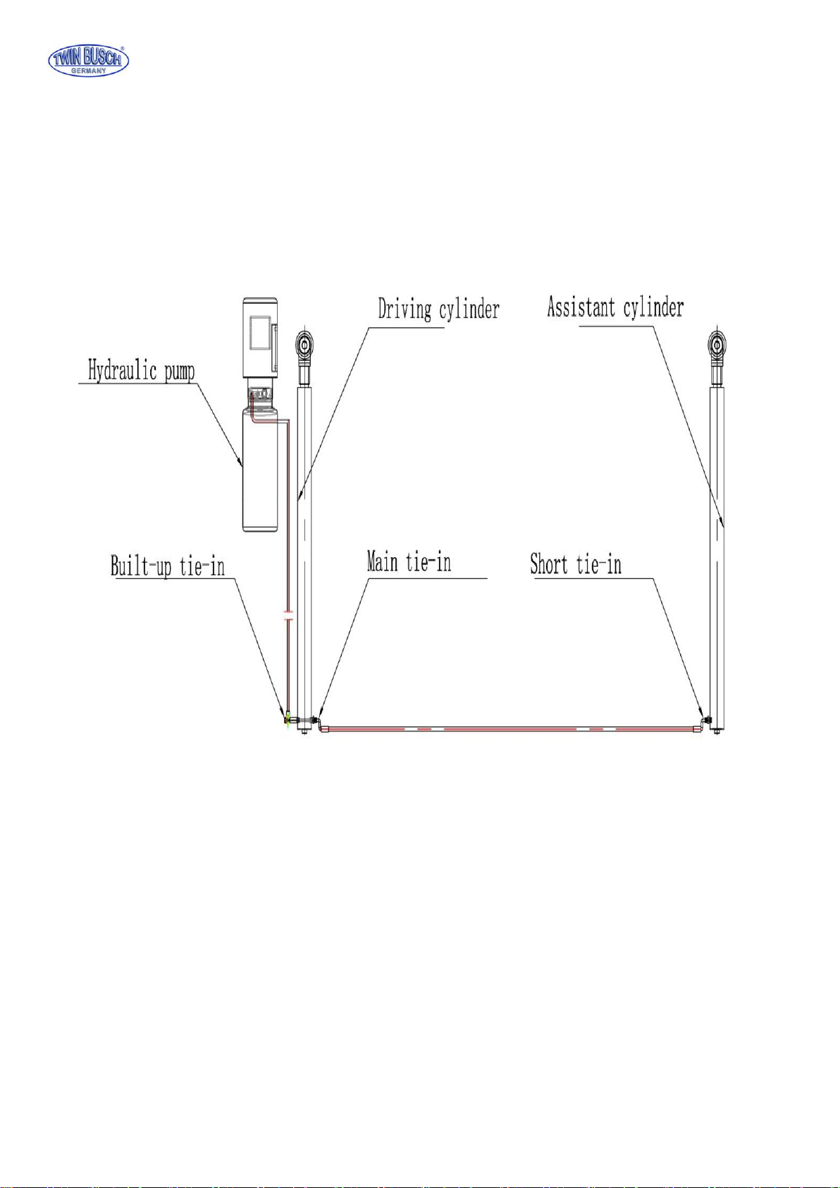
3.2.2 All hydraulic, pneumatic and electrical connections should be checked for leakage and tightness before the lift is
used.
3.2.3 All screws and bolts should be checked for tightness.
3.2.4 Do not use a vehicle on the lift for the first trial.
3.3 Installation
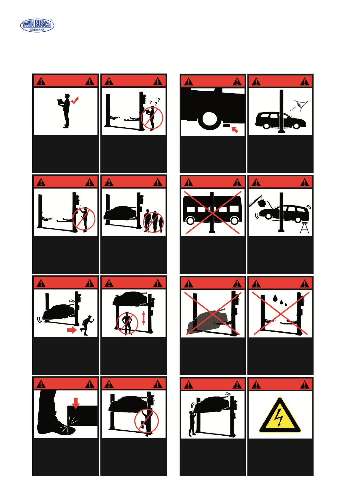
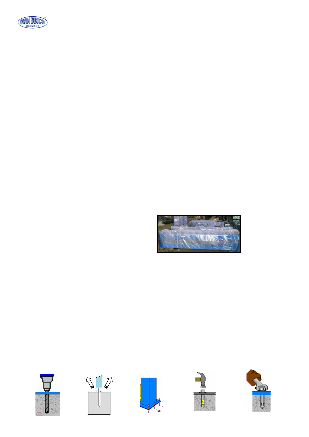
Step 1: Remove from the packing and prepare the spare parts and covers needed.
(This step is very important and the information in the diagram should be read and understood before
operating).
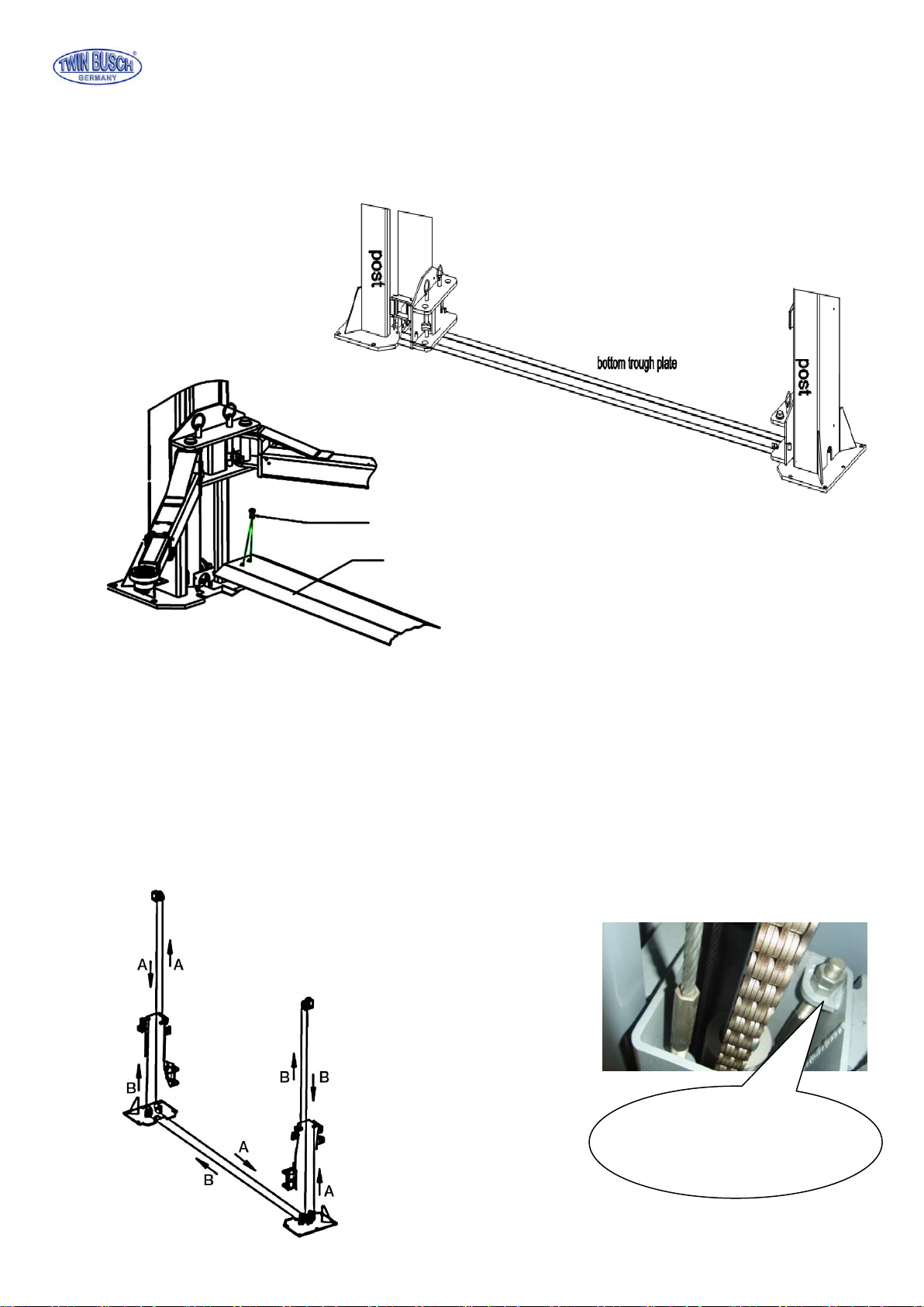
Step 2: With the aid of a forklift remove the supports between the two posts, and then remove the frame screws
Attention: Please take care that the posts cannot fall or slip as this could cause injury or damage.
Step 3: After removing the first post place a support under the other post and then remove the screws.
Step 4: Fit the post extensions and then mount the cross beam. (Make sure all bolts are tightened)
Step 5: Erect the posts, main post first and then the assistant post.
1. Drill anchor holes for each plug bolts on the ground with an electrical drill. Make sure to drill vertically.
2. After holes have been drilled, remove thoroughly the debris and dust in them and ascertain that the posts
stay upon the circle previously drew by chalk.
Step 6: 1. Drill the holes for the floor anchors making sure that the holes are vertical.
2. Remove all dust and particles and place the anchors in the holes, use a hammer to drive in the bolts.
3. Tighten to recommended torque.

TWIN BUSCH GmbH
Technical changes for purposes of a technical advancement as well as deviation in colour, errors and printing mistakes are reserved.
page 8 of 45
Step 7: Mount the safety mechanism and the electro magnets then the protection cover.
Mount the Limit switch on the upper inner side oft he main post.
Safety latch
Bracket
Electro magnet
M5*10 Screw
M6*16 Screw
Safety latch
Electro magnet
Protection cover

TWIN BUSCH GmbH
Technical changes for purposes of a technical advancement as well as deviation in colour, errors and printing mistakes are reserved.
page 9 of 45
Step 7:Fitting the bottom protection plate.
Raise the lift to about 800mm and activate the safety locks, then mount the base plate
Screw/dowel
bottom trough plate
Step8: Connecting the steel cables.
1. Raise carriages on both sides approximately 800mm above the ground.
2. Make sure that the safety locks on each column are fully engaged before attempting to route the cables.
3. Carriages must have the same height from the floor before proceeding.
4. Fit the cables as shown in the diagram.
5. The cables should be so adjusted that the safety mechanism engages simultaneously when lifting.
6. The cables must be secured and lubricated.
Cable adjustment nut, make
sure both nuts are
tightened!

TWIN BUSCH GmbH
Technical changes for purposes of a technical advancement as well as deviation in colour, errors and printing mistakes are reserved.
page 10 of 45
Step9: Connect the oil hose.
Connect the oil hose as in the following diagram.

TWIN BUSCH GmbH
Technical changes for purposes of a technical advancement as well as deviation in colour, errors and printing mistakes are reserved.
page 11 of 45
Step10: Mounting the Pump and the control box.
1. Mount the power unit onto the main post.
2. Connect the pump with the control box as in the wiring diagram.
Step 11: Install the oil hose protector.
Limit switch
M5*30 Screw
Protection plate

TWIN BUSCH GmbH
Technical changes for purposes of a technical advancement as well as deviation in colour, errors and printing mistakes are reserved.
page 12 of 45
Step12: Install the lifting arms.
Connect the lifting arm and the carriage with the pins. Install the swing arms on the carriages and make sure the
safety lock and half moon are correctly positioned.
Filling with Hydraulic oil
The oil tank has a volume of 10 Liters and should be filled to at least 80% to ensure the pump has enough oil.
(Recommended oil HLP 32).
Step 14: Testing
1. When testing the lift for the first time NEVER do the test with a vehicle on the lift.
2. Check all the connections.
Step 15: Mount the post covers and the door protections.(Optional)
Chain protection
Door protection
Oil hose protectoion plate
Half moon lock
Safety pin

TWIN BUSCH GmbH
Technical changes for purposes of a technical advancement as well as deviation in colour, errors and printing mistakes are reserved.
page 13 of 45
3.4 Check list after installation
S/N
To check
Y
N
1
Are the posts vertical? (90°)
2
Are both posts parallel to each other?
3
Are all oil connections correct?
4
Are the cables secure and tight?
5
Are the lifting arms correctly mounted?
6
Are all electrical connections correct?
7
Are all bolts, screws and joints secure?
8
Are all moving parts and cables lubricated?
4. Operation instructions
4.1 Safety checks
4.1.1 Check all connections for leaks, if no leaks are found the lifting process can begin.
4.1.2 If the safety devices are not working the lift may not be used.
4.1.3 When a vehicle is lifted it is very important that the weight is correctly balanced, the manufacture and dealers will
take no responsibility for any damage or injury caused by improper use.
4.1.4 Operators and other personnel must stand clear of the lift when in use. Personnel must stand in a designated safety
area.
4.1.5 When the lift has reached the desired height the power should be turned off to avoid tampering.
4.1.6 Make sure that all safety locks are engaged before working under the lift.
4.2 Descriptions of control box
Description
Function
Main switch
On/Off
Power indicator
Shows Power supply
UP-Button
To lift
Safety lock
To apply safety lock
DOWN-Button
To lower the lift
Emergency stop button
Turns off power supply

TWIN BUSCH GmbH
Technical changes for purposes of a technical advancement as well as deviation in colour, errors and printing mistakes are reserved.
page 14 of 45
Start
Turn on the power switch
Press UP button
Motor drives the gear pump work
Cylinder piston drives the chain work
Chain drives the carriage rise
The lift is raised
Start
Turn on the power switch
Press the DOWN button
The lift is lowered
4.3 Flow chart for operation
4.4 Operating instructions
Raising the lift
1. Always read the instruction and safety manuals before working with the lift.
2. Drive the vehicle onto the centre of the lift making sure the weight is evenly displaced.
3. Make sure that the vehicle can’t roll or move from the desired position.
4. Turn on the main switch and press the UP button (STOP and check once again that lifting pads are securely positioned)
then raise until the lift has reached the desired height.
5. When the lift has reached the required level press the safety lock button to engage the mechanical safety mechanism.
6. When all safety precautions have been taken, turn off the main switch and check the stability before working on the
Lowering the lift
1. Turn on the power.
2. Press the DOWN (I) button. The lift will automatically rise to disengage the safety mechanism before going down.
The lift will stop at approximately 800mm from the floor.
3. Press the DOWN (II) button to lower the lift, an alarm signal will be heard as the lift descends to the floor.
4. Remove the vehicle.
Raising
Lowering

TWIN BUSCH GmbH
Technical changes for purposes of a technical advancement as well as deviation in colour, errors and printing mistakes are reserved.
page 15 of 45
4.5 Emergency lowering in case of power cut
When the safety mechanism is not engaged:
a. Release and hold all four Electromagnets, on the posts simultaneously.
b. Turn the valve screw manually.
(Press the screw in and turn left to open and right to close.„OPEN“, „CLOSE“)
Electromagnet
Electromagnetic valve

TWIN BUSCH GmbH
Technical changes for purposes of a technical advancement as well as deviation in colour, errors and printing mistakes are reserved.
page 16 of 45
When t
he safety mechanism is engaged:
a. Open the hydraulic plug to enable the connection of a manual pump. (Optional).
b. Press the pump lever to fill the cylinder with oil (optional) the safety can now be released.
c. Release all four Electromagnets, on the posts simultaneously.
Repeat process (b)
Hydraulic plug (Hydraulic connection)
Motor
Oil tank
Hydraulic-
connection
Hydraulic-
connection
Motor
Oil tank
Hydraulic plug (Hydraulic connection)
Hydraulic pump
Electromagnet

TWIN BUSCH GmbH
Technical changes for purposes of a technical advancement as well as deviation in colour, errors and printing mistakes are reserved.
page 17 of 45
Trouble shooting
Attention: Please don’t hesitate to contact us if you can’t solve the problem yourself.
We will help as soon as possible. To help us help you please send a detailed description of your problem with pictures if
possible. This way we can diagnose your problem much quicker.
PROBLEME
Cause
Solution
Abnormal noise.
Excessive wear on the inside of the post.
Lubricate the inner side (grease).
Dirt on the post runner.
Clean the runners.
Motor does not run /
lift does not rise.
Loose wires
Check wires/ connections
Motor is defect.
Replace
The limit switch is defect or loose connector
Reconnect or replace the switch
Motor runs, lift doesn’t
rise
Motor is running backwards
Check wiring.
Pressure valve is loose or blocked.
Tighten / Clean.
Gear pump is defect.
Replace.
Oil level too low.
Top up Oil.
Oil hose loose or damaged.
Tighten or replace.
Cushion valve loose or blocked
Clean / Tighten
Lift lowers too slowly.
Oil hose is leaking
Tighten / Replace.
Cylinder piston leaking
Replace gasket.
Direction valve is leaking
Clean /replace.
Pressure valve is leaking.
Clean / replace.
Manual or electrical release valve is blocked
Clean / replace.
Lifting to slow
Oil filter blocked or not sealed
Clean / replace.
Oil level too low.
Top up oil
Pressure valve wrongly adjusted
Adjust
Oil is too hot. (over 45°C)
Change oil
Cylinder gasket.
Replace
Lift is to slow
Restriction valve blocked
Clean / replace.
Hydraulic oil dirty
Change oil.
Release valve blocked
Clean
Oil hose damaged.
Replace
Steel cable is worn
Is not lubricated
Lubricate / Replace

TWIN BUSCH GmbH
Technical changes for purposes of a technical advancement as well as deviation in colour, errors and printing mistakes are reserved.
page 18 of 45
Maintenance
Simple low cost maintenance will enhance the safety and prolong the life of your lift.
The service intervals can be chosen in between working times. Here are the lubrication (greasing points):
6.1. Daily service before use
It’s very important to have a daily safety check before the lift is used. Discovery of worn or defect parts saves time and
expensive repairs, and loss through damages or injuries.
Check oil hoses for leakage and damage.
Check all electrical connections and make sure they are in good condition.
Check that all bolts are securely tightened.
Check that the safety mechanism is working properly and no visible ware can be seen.
6.2. Weekly service
Check all moving parts.
Check the movement of safety parts.
Raise the lift completely to check the oil level, refill if necessary.
Check that all bolts are securely tightened.
6.3. Monthly service
Check that all bolts are securely tightened.
Check that all moving parts have enough lubrication and the whole construction is in good working order.
If damaged parts are discovered they should be replaced
6.4. Yearly service
Empty and clean the oil tank, replace with new oil
Replace the oil filter.
When the user follows the above service suggestions the lift will stay in a good working condition and
unnecessary costs can be avoided.
S/N
Description
1
Cable pulley (top)
2
Steel cable
3
Chain wheel
4
Chain
5
Slide
6
Bolt
7
Safety lock
8
Lifting arm
9
Lifting plate
10
Cable pulley (bottom)

TWIN BUSCH GmbH
Technical changes for purposes of a technical advancement as well as deviation in colour, errors and printing mistakes are reserved.
page 19 of 45
Attachment (Pack List)
S/N
Material #
Name
Drawing#
Property
Qty
1
Power side post assembly
FL-8224E-A1
Assembly
1
2
Post assembly
FL-8224E-A2
Assembly
1
3
Carriage assembly
FL-8224E-A3
Assembly
2
4
Power unit
Assembly
1
5
Oil cylinder
FL-8224-A4-B3
Assembly
1
6
Drive oil cylinder
FL-8224-A4-B2
Assembly
1
7
Electrical system
Assembly
1
8
Control box
1
9
Wire package
1
10
Steel cable L=8820mm
FL-8224E-A6
Assembly
2
11
Long arm
FL-8224-A7
Assembly
2
12
Short arm
TW-235E-A8
Assembly
2
13
14
Base cover plate
FL-8224-A10
Powder-coating
1
Carton(includes the following )
17
18
Arm shaft
FL-8224 -A12
Zinc-plating
4
19
20
Short feet-protection fender
FL-8224 –A18-B4
Powder-coating
2
21
Long feet-protection fender
FL-8224–A7-B4
Powder-coating
2
22
Lifting tray assembly
FL-8224 –A7-B3
Assembly
4
23
Rubber oil hose L=500mm
Assembly
1
24
Rubber oil hose L=2900mm
8224E-B4-B2
Assembly
1
25
Safety locking plate
FL-8224E –A1-B2
Zinc-plating
26
27
Positioning block
FL-8224E –A1-B3
Zinc-plating
28
Hose & wire cover
FL-8224E –A1-B8
Powder-coating
6
29
Chain protection cloth
FL-8224 -A11
Assembly
2
30
Rod of chain protection cloth
FL-8224 -A13
Zinc-plating
4
31
Rubber protection pad
FL-8224 –A3-B7
Rubber
2
32
Nylon washer
FL-8224 -A17
Rubber
10
33
34
Hex head full swivel nut
M10*35
Standard
4
35
Hex socket cylinder head screw
M8*12
Standard
8
36
Cross cap screw
M6*10
Standard
28
37
Cross cap screw
M6*30
Standard
12
38
Cross cap screw
M6*16
Standard
4
39
Cross sunken head screw
M8*16
Standard
4
40
Class C flat washer
M6
Standard
8
41
Class C flat washer
M10
Standard
4
42
Spring washer
M10
Standard
4
Hex nut
M6
Standard
8
Hex nut
M10
Standard
4
Type B circlip
38
Standard
4
Expansion bolt
M18*180
Standard
10

TWIN BUSCH GmbH
Technical changes for purposes of a technical advancement as well as deviation in colour, errors and printing mistakes are reserved.
page 20 of 45
Attachment 2, Dimensions diagram
Table of contents
Other twin busch Lifting System manuals
Popular Lifting System manuals by other brands

Norco
Norco 82990C Setup, operating, maintenance instructions

Dannmar Equipment
Dannmar Equipment Max Jax Installation and operation

Grundfos
Grundfos Multilift MD1 Installation and operating instructions

Guldmann
Guldmann Cross hanger instructions

LGMG
LGMG SR1018D Operation manual

Big Lift
Big Lift Big Joe M22 Operator's manual

Braun
Braun NVL Vista 02 Series Service manual

LSI-Robway
LSI-Robway RCI-1550 HRT instruction manual

HiGH-LiFT
HiGH-LiFT YL130 user manual

Aqua Creek Products
Aqua Creek Products F-714RTC quick start guide

DINGLI
DINGLI GTWY8-1200 Series operators manual with maintenance information

Avanti
Avanti OCTOPUS L80 Installation and maintenance manual