SKIDRIL G23 Application guide

SPECIFICATIONS
UNIT SERIAL NUMBER
_________________________
SKIDRIL
P.O. BOX 8041
GREENSBORO, NC 27419
TEL: 800-843-3745
MODEL G23
DIMENSIONS 32”X18”X13
WEIGHT 50 LB.
ENGINE
TYPE SINGLE CYLINDER,
AIR COOLED, 2 CYCLE
DISPLACEMENT 40.2 CC
OUTPUT 1.4PS/6000 RPM
CARBURATION DIAPHRAGM,
W/PRIMER AND
CHOKE
AIR CLEANER WASHABLE, SEMI-WET
STARTER RECOIL
IGNITION ELECTRONIC,
SPARK PLUG NGK BPM4A
FUEL TANK SIZE 0.28 US GALLON
FUEL MIX RATIO 20-25:1
FUEL MIX OIL TYPE 2 CYCLE
FUEL TYPE REGULAR NO LEAD
IMPACT RATE 1200 BPM
IMPACT FORCE 60-70 FT-LB.
IMPACT SECTION
LUBRICATION OIL BATH
LUBRICANT TYPE SAE 10W-30
LUBRICANT VOL 5 0Z
LUBRICANT USE 1.3 OZ /8 HOURS
12
1-800-843-3745
OPERATION & PARTS
MANUAL
SKIDRIL
ENGINE BREAKER G23
ANY PERSON
OPERATING THIS
MACHINE SHOULD
READ AND
UNDERSTAND THIS
MANUAL FIRST!
FOLLOW ALL SAFETY
INSTRUCTIONS

Page
4
5
7
9
10
12
Contents
CONTROL IDENTIFICATION
OPERATION
MAINTENANCE
EXPLODED VIEW
PARTS LIST
SPECIFICATIONS
3
1 MA02E001A1 STAY 1
2 E002A3 GUIDE 1
3 E003A0 BUSHING 1
4 E004A1 LINER 1
5 E005A1 PISTON RING 1
6 E006A2 HAMMER PISTON 1
7 E007A0 PISTON 1
8 E008A1 BUSHING 1
9 E009A1 CON-ROD 1
10 E010A0 SPACER 1
11 E011A1 PIN 1
12 E012A1 BOLT 4
13 E013A0 COLLAR 1
14 E014A0 PINION 1
15 E015A1 CLUTCH SHAFT 1
16 E016A1 KEY 1
17 E017A1 BEARING COVER 1
18 E018A0 PACKING 1
19 E019A1 LEVER 1
20 E020A0 HANDLE SUPPORT 1
21 E021A1 LID 2
22 E025A0 PACKING 1
23 D051A0 CLUTCH COVER 1
24 D052A1 CRANK BRACKET 1
25 D053A2 CYLINDER COVER 1
26 D054A1 CRANK SHAFT 1
27 D055A2 GUARD PIPE 1
28 D058A1 MUFFLER COVER 1
29 C071A2 CYLINDER COVER 1
30 C072B0 FRONT END 1
31 C073A0 CRANK CASE 1
32 MIKTE119A1 HANDLE GRIP 2
33 1120-414 HANDLE GRIP 1
34 1120-422 GRIP SHAFT 1
35 1110-402-01 LATCH 1
36 1110-410-01 LOCK SRPING 1
37 1014-112 PISTON PIN RING 2
38 1044-818A COMP. PISTON PIN 1
39 1044-6190 BOLT M8X17 6
40 MB03E108A1 COLLET (1-1/4X6) 1
51 0G-50 O-RING 2
52 0G-55 O-RING 1
53 0S-44 O-RING 1
54 0S-50 O-RING 1
55 0S-90 O-RING 1
56 0G-75 O-RING 1
57 CL0050C0 DUST SEAL 1
58 AP0687F0 TVC OIL SEAL 1
Part List
No. Part No. Name QTY
10

Maintenance cont.
M1: Impact Oil Sight
M2: Spark Plug Gap
M3: Carb Filter
To Check Oil Level: Be sure Machine is in
the vertical position and the oil level is
somewhere between the two horizontal lines
To Check Plug Gap: First remove and clean
carbon or dirt using a wire brush. Using a
feeler gauge check and adjust the plug gap
to .024-.028”.
To Check or Clean Air Filter: First unlock
cleaner cover and twist cover off as shown.
Wash filter in appropriate cleaner, then wring
dry. Put a few drops of motor oil on it and
squeeze to distribute. Re-install.
Lock Cover
Filter
Gap
Notice:
*Do: Always fill/
check the oil level
with the machine in
the upright position.
Notice:
*Do not: Over fill
the machine with
lubricant
Notice:
*Be sure to apply
sufficient torque to
the spark plug, to
eliminate unwanted
loosening.
Notice:
*Never operate the
machine with a
missing or damaged
filter.
8
PREPARATION FOR USE
1. IMPACT LUBRICANT:
- Remove fill cap (item 12, p4).
- keep breaker in vertical upright
position while filling.
- use 10w30 4 cycle oil
- fill to the lip and install fill cap.
2. FUELING:
-Mix 20-25 to 1 regular no-lead
gasoline with 2 cycle engine oil.
-Fuel tank will hold approx. 1 quart.
3. OPERATION:
Before operation perform daily
inspection per maintenance section of
this manual.
a. Fill fuel tank (item 1, p4).
b. Attach a tool for the required job
(chisel, drive head etc.) by first opening
the tool latch (item 10, p4), by pushing
down with your foot.
c. Insert tool and close tool latch by
pushing upwards.
Operation
NOTICE:
* Do not use 2 cycle
or non 10W30 type
oils.
WARNING:
*Do not: Fuel a hot
machine!
*Do not: Smoke
While Fueling!
*Do not: Operate
the machine without
protective/safety
clothing and
equipment!
*Do not: Use the
machine without first
contacting the
Utilities for a
‘Locate’!
*Do not: Use the
machine without
reading and
understanding the
safety section of this
manual!
!
5

D. Start the engine by:
1. Close the choke lever item14, p4) by
pushing it upwards.
2. Push the primer button (item 13,
p4) 3-5 times.
3. Pull the starter grip while holding the
throttle (item 15, p4) in the down
position.
4. Quickly release the throttle lever
when the engine starts.
5. Gradually open the choke lever, by
pushing downwards as the engine
warms up.
E. Stopping the engine:
-Press the stop button (item 18, p4) to
kill the engine.
-If the kill switch malfunctions, you can
stop the engine by pressing the throttle
lever down and closing the choke.
F. Operation:
1. By pressing the throttle lever the
machine speed and impact force is
increased.
2. You need not apply excessive
pressure on the machine during
operation.
Operation continued
Warning:
*Discontinue use of
the machine until
repairs can be
made!
!
WARNING:
*Do not: Operate
a machine with
missing, damaged or
loose parts.
Notice:
*Failure to follow
this schedule may
result in damage to
the machine, and
could void the
warranty.
*Service beyond
what is indicated
here should not be
performed by
untrained persons,
and could void the
warranty.
1. DAILY INSPECTION:
A. Look for loose or missing
nuts, bolts or screws.
B. Check the starter rope for wear and
replace if required.
C. Inspect the tool blade and shank for
cracks and discard if required.
D. Check the impact section lubricant level
(item 9, p4)., see sketch m1 , p8 .
E. Check the air cleaner and clean if
required, see sketch
m2, p8.
2. PERIODIC MAINTENANCE:
Item time (hrs)
Cleaning exterior daily
Clean/adjust plug 50
Replace impact oil 150
Inspect/replace clutch 300
Replace O-ring/seal 300
Clean exhaust port 300
Clean Carburetor 300
3. Extended storage:
A. Remove fuel from tank and burn excess
in engine.
B. Place a few drops of 2 cycle oil in engine
through spark plug opening.
C. Clean and keep dry.
!
Maintenance
67
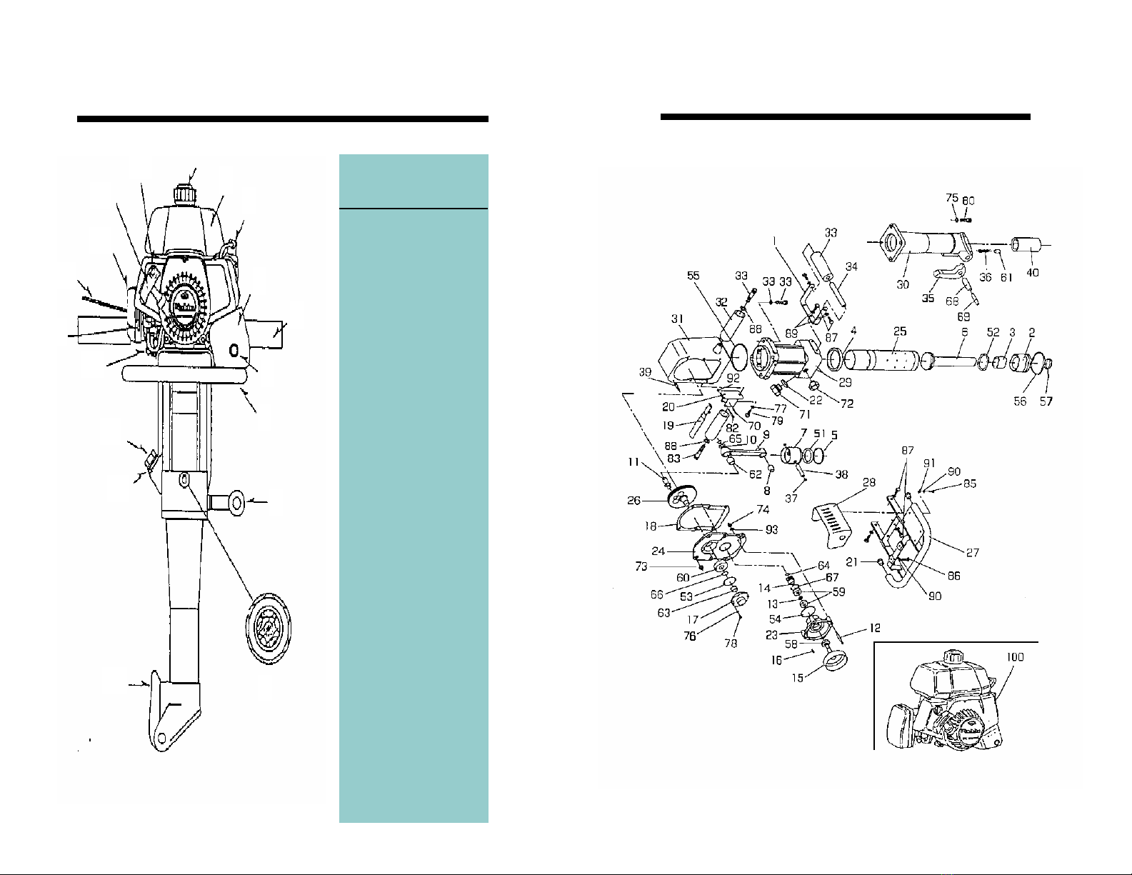
Item
1. Fuel cap
2. Fuel tank
3. Spark plug
4. Muffler cover
5. Handle
6. Exhaust outlet
7. Guard handle
8. Side handle
9. Impact oil window
10. Tool latch
11. Impact oil inlet
12. Impact oil cap
13. Primer pump
14. Choke lever
15. Throttle lever
16. Air cleaner
17. Starter grip
18. Stop switch
Controls
1
11
2
3
4
5
6
7
8
9
10
12
13
14
15
16
17
18
4
Exploded View
9
SAFETY FIRST
READ, UNDERSTAND AND FOLLOW
SAFETY GUIDELINES AND SAFE WORK
PRACTICES.
Special
notice
goes here
TAKE NOTE OF WARNINGS IN THIS MANUAL
AS THEY IDENTIFY INSTRUCTIONS INTENDED
TO PREVENT INJURY TO YOU OR OTHERS.
NOTICES:, ARE INTENDED TO PREVENT
DAMAGE TO THE MACHINE OR PROPERTY.
WARNING:
DO NOT: USE EQUIPMENT IN
APPLICATIONS FOR WHICH IT IS NOT INTENDED.
DO NOT: USE IMPROPERLY TRAINED OR
UNQUALIFIED PERSONNEL TO OPERATE
THIS EQUIPMENT.
DO NOT: LEAVE MACHINE RUNNING
UNATTENDED OR WHEN NOT IN USE.
DO NOT: REFUEL A HOT OR RUNNING ENGINE.
DO NOT: SPILL FUEL WHEN FUELING THE
ENGINE.
DO NOT: SMOKE WHILE FUELING OR
OPERATING THE MACHINE.
DO NOT: REFUEL NEAR AN OPEN FLAME OR
SPARK.
DO NOT: OPERATE THE MACHINE WITHOUT
PROPER SAFETY PROTECTION SUCH AS
PROTECTIVE EYEWEAR, SAFETY BOOTS,
EAR PROTECTION, HARD HAT, GLOVES ETC.
DO NOT: OPERATE THE MACHINE INDOORS OR IN AN
AREA WHERE EXHAUST GASESMAY COLLECT., OR
WHERE VENTILATION IS NOT ADEQUATE.
DO NOT: OPERATE THE MACHINE WITHOUT SOLID
FOOTING OR WITH THE MACHINE ELEVATED ABOVE
YOUR HEAD.
DO NOT: STORE THE MACHINE IN A PLACE OR POSITION
THAT IT MAY FALL , DROP OR SLIDE FROM WHEN NOT IN USE.
!
NOTICE:
!
2
59 6001 BEARING (C-TYPE) 2
60 6204 BEARING (C-TYPE) 1
61 QC-12X18 ROLLER 1
62 TA 1520Z NEEDLE BEARING 1
63 TLA1512Z NEEDLE BEARING 1
64 CS-12 SNAP RING 1
65 CS-15 SNAP RING 1
66 CS-20 SNAP RING 1
67 CH-28 SNAP RING 1
68 PR16X50 SPRING PIN 1
69 PR10X50 SPRING PIN 1
70 PR 4X28 SPRING PIN 1
71 NK-2OIL CAP 1
72 FG-10 OIL WINDOW 1
73 NFL-8 LOCK NUT W/FLANGE 6
74 NFL-6 LOCK NUT W/FLANGE 4
75 WF2L-10 SPRING WASHER 8
76 WF2L-5 SPRING WASHER 4
77 WF2L-8 SPRING WASHER 2
78 SBH-5X12 HEX SOCKET BOLT 4
79 SBH-8X20 HEX SOCKET BOLT 2
80 BH-10X30 HEX SOCKET BOLT 4
81 BH-10X35 HEX SOCKET BOLT 4
82 BH- 5X35 HEX SOCKET BOLT 1
83 BH-12X50 HEX SOCKET BOLT 1
84 BH-12X55 HEX SOCKET BOLT 1
85 B-6X12 HEX BOLT 4
86 B-6X25 HEX BOLT 2
87 B-8X20 HEX BOLT 8
88 WS-12 PRING WASHER 2
89 WS-8 SPRING WASHER 8
90 WS-6 SPRING WASHER 6
91 WP-6 PLAIN WASHER 6
92 NN-5 NYLON NUT 1
93 W6S1 SEAL WASHER 4
100 EC04 ENGINE 1
Parts List Continued
No. Part No. Name QTY
NOTE: WHEN ORDERING PARTS
PLEASE INCLUDE SERIAL NUMBER
FOUND ON PAGE 12 OF THIS
MANUAL.
11
Table of contents


