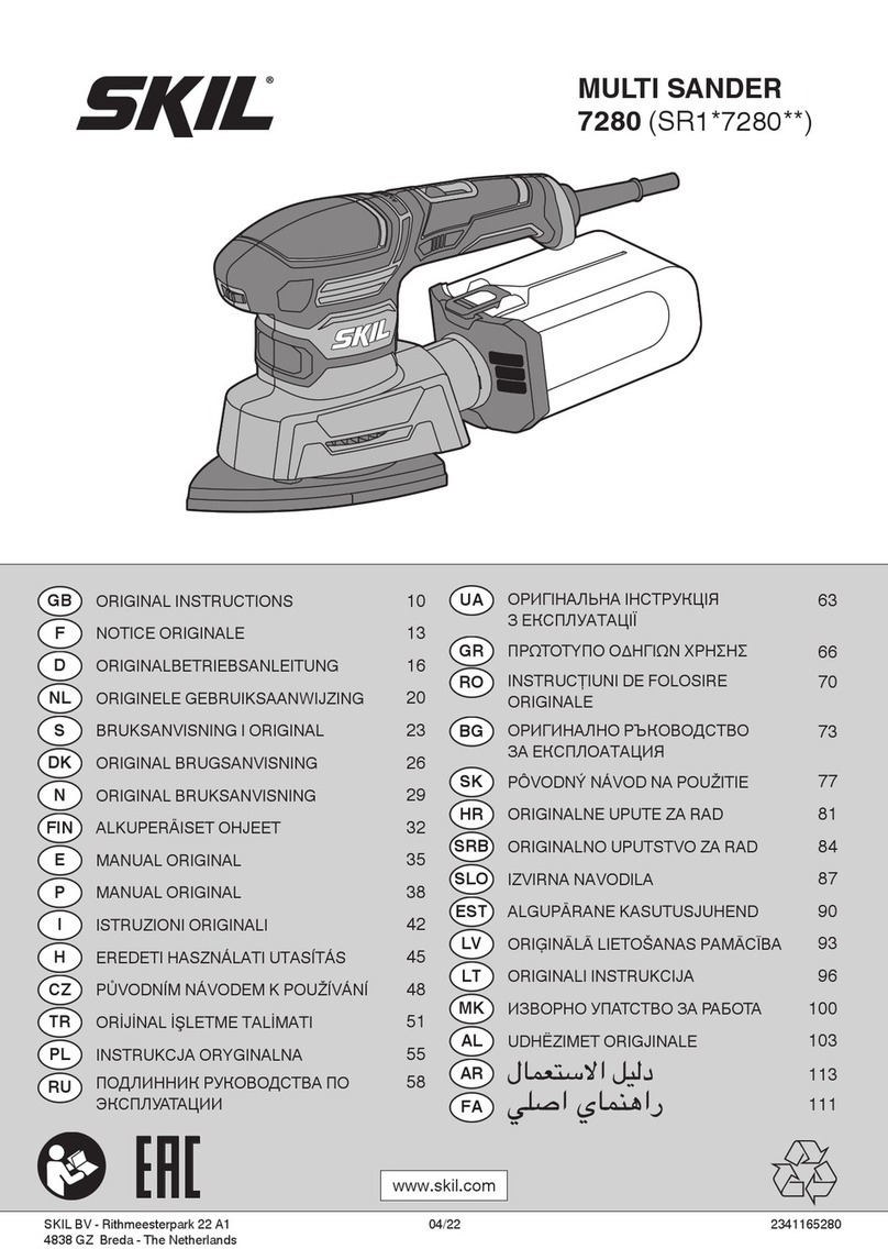
Skil 7300 Assembly instructions

IMPORTANT: IMPORTANT : IMPORTANTE:
Read Before Using Lire avant usage Leer antes de usar
Operating/Safety Instructions
Consignes de fonctionnement/sécurité
Instrucciones de funcionamiento y seguridad
7300
For English Version Version française Versión en español
See page 2 Voir page 14 Ver la página 26
1-877-SKIL999 (1-877-754-5999) www.skil.com
Call Toll Free for
Consumer Information
&Service Locations
Pour obtenir des informations
et les adresses de nos centres
de service après-vente,
appelez ce numéro gratuit
Llame gratis para
obtener información
para el consumidor y
ubicaciones de servicio
SM 2610938371 01-06 1/12/06 8:10 AM Page 1

-2-
Work area safety
Keep work area clean and well lit.
Cluttered or dark areas invite accidents.
Do not operate power tools in explosive
atmospheres, such as in the presence of
flammable liquids, gases or dust. Power
tools create sparks which may ignite the dust
or fumes.
Keep children and bystanders away while
operating a power tool. Distractions can
cause you to lose control.
Electrical safety
Power tool plugs must match the outlet.
Never modify the plug in any way. Do not
use any adapter plugs with earthed
(grounded) power tools. Unmodified plugs
and matching outlets will reduce risk of
electric shock.
Avoid body contact with earthed or
grounded surfaces such as pipes,
radiators, ranges and refrigerators. There
is an increased risk of electric shock if your
body is earthed or grounded.
Do not expose power tools to rain or wet
conditions. Water entering a power tool will
increase the risk of electric shock.
Do not abuse the cord. Never use the cord
for carrying, pulling or unplugging the
power tool. Keep cord away from heat, oil,
sharp edges or moving parts. Damaged or
entangled cords increase the risk of electric
shock.
When operating a power tool outdoors,
use an extension cord suitable for
outdoor use. Use of a cord suitable for
outdoor use reduces the risk of electric
shock.
Do not use AC only rated tools with a DC
power supply. While the tool may appear to
work, the electrical components of the AC
rated tool are likely to fail and create a
hazard to the operator.
If operating the power tool in damp
locations is unavoidable a Ground Fault
Circuit Interrupter (GFCI) must be used to
supply the power to your tool. GFCI and
personal protection devices like electrician’s
rubber gloves and footwear will further
enhance your personal safety.
Personal safety
Stay alert, watch what you are doing and
use common sense when operating a
power tool. Do not use a power tool while
you are tired or under the influence of
drugs, alcohol or medication. Amoment of
inattention while operating power tools may
result in serious personal injury.
Use safety equipment. Always wear eye
protection. Safety equipment such as dust
mask, non-skid safety shoes, hard hat, or
hearing protection used for appropriate
conditions will reduce personal injuries.
Avoid accidental starting. Ensure the
switch is in the off-position before
plugging in. Carrying power tools with your
finger on the switch or plugging in power
tools that have the switch on invites
accidents.
Remove any adjusting key or wrench
before turning the power tool on. Awrench
or a key left attached to a rotating part of the
power tool may result in personal injury.
Do not overreach. Keep proper footing
and balance at all times. This enables
better control of the power tool in unexpected
situations.
Dress properly. Do not wear loose
clothing or jewelry. Keep your hair,
clothing and gloves away from moving
parts. Loose clothes, jewelry or long hair can
be caught in moving parts.
If devices are provided for the connection
of dust extraction and collection facilities,
ensure these are connected and properly
used. Use of these devices can reduce dust-
related hazards.
Read all instructions. Failure to follow all instructions listed below may
result in electric shock, fire and/or serious injury. The term “power tool”
in all of the warnings listed below refers to your mains-operated (corded) power tool or
battery-operated (cordless) power tool.
SAVE THESE INSTRUCTIONS
!
WARNING
General Safety Rules
SM 2610938371 01-06 1/12/06 8:10 AM Page 2
-3-
Keep handles dry, clean and free from oil
and grease. Slippery hands cannot safely
control the power tool.
Power tool use and care
Do not force the power tool. Use the
correct power tool for your application.
The correct power tool will do the job better
and safer at the rate for which it was
designed.
Do not use the power tool if the switch
does not turn it on and off. Any power tool
that cannot be controlled with the switch is
dangerous and must be repaired.
Disconnect the plug from the power
source and/or the battery pack from the
power tool before making any
adjustments, changing accessories, or
storing power tools. Such preventive safety
measures reduce the risk of starting the
power tool accidentally.
Store idle power tools out of the reach of
children and do not allow persons
unfamiliar with the power tool or these
instructions to operate the power tool.
Power tools are dangerous in the hands of
untrained users.
Maintain power tools. Check for
misalignment or binding of moving parts,
breakage of parts and any other condition
that may affect the power tools operation.
If damaged, have the power tool repaired
before use. Many accidents are caused by
poorly maintained power tools.
Keep cutting tools sharp and clean.
Properly maintained cutting tools with sharp
cutting edges are less likely to bind and are
easier to control.
Use the power tool, accessories and tool
bits etc., in accordance with these
instructions and in the manner intended
for the particular type of power tool,
taking into account the working
conditions and the work to be performed.
Use of the power tool for operations different
from those intended could result in a
hazardous situation.
Use clamps or other practical way to
secure and support the workpiece to a
stable platform. Holding the work by hand
or against your body is unstable and may
lead to loss of control.
Service
Have your power tool serviced by a
qualified repair person using only identical
replacement parts. This will ensure that the
safety of the power tool is maintained.
Develop a periodic maintenance schedule
for your tool. When cleaning a tool be
careful not to disassemble any portion of
the tool since internal wires may be
misplaced or pinched or safety guard
return springs may be improperly
mounted. Certain cleaning agents such as
gasoline, carbon tetrachloride, ammonia, etc.
may damage plastic parts.
SAVE THESE INSTRUCTIONS
SM 2610938371 01-06 1/12/06 8:10 AM Page 3

-4-
Safety Rules for Orbital Sanders
Unplug the sander before changing
accessories. Accidental start-ups may occur
if sander is plugged in while changing an
accessory.
Use clamps or other practical way to
secure and support the workpiece to a
stable platform. Holding the work by hand
or against your body is unstable and may
lead to loss of control.
Your tool is equipped with a dust
canister, empty it frequently, after
completion of sanding and before storing
the sander. Be extremely careful of dust
disposal, materials in fine particle form may
be explosive. Do not throw sanding dust on
an open fire. Combustion from mixture of
varnishes, lacquers, polyurethane, oil or
water with dust particles can occur if there is
astatic discharge, spark introduced in the
box, or excessive heat.
Always wear eye protection and a dust
mask for dusty applications and when
sanding overhead. Sanding particles can
be absorbed by your eyes and inhaled easily
and may cause health complications.
Use special precautions when sanding
chemically pressure treated lumber, paint
that may be lead based, or any other
materials that may contain carcinogens. A
suitable breathing respirator and protective
clothing must be worn by all persons
entering the work area. Work area should be
sealed by plastic sheeting and persons not
protected should be kept out until work area
is thoroughly cleaned.
Do not wet sand with this sander. Liquids
entering the motor housing is an electrical
shock hazard.
Do not use sandpaper intended for larger
sanding pads. Larger sandpaper will extend
beyond the sanding pad causing snagging,
tearing of the paper or kick-back. Extra paper
extending beyond the sanding pad can also
cause serious lacerations.
Some dust created by
power sanding, sawing,
grinding, drilling, and other construction
activities contains chemicals known to
cause cancer, birth defects or other
reproductive harm. Some examples of
these chemicals are:
•Lead from lead-based paints,
•Crystalline silica from bricks and cement
and other masonry products, and
•Arsenic and chromium from chemically-
treated lumber.
Your risk from these exposures varies,
depending on how often you do this type of
work. To reduce your exposure to these
chemicals: work in a well ventilated area,
and work with approved safety equipment,
such as those dust masks that are specially
designed to filter out microscopic particles.
!
WARNING
SM 2610938371 01-06 1/12/06 8:10 AM Page 4

-5-
IMPORTANT: Some of the following symbols may be used on your tool. Please study them
and learn their meaning. Proper interpretation of these symbols will allow you to operate the
tool better and safer.
Symbol Name Designation/Explanation
V Volts Voltage (potential)
A Amperes Current
Hz Hertz Frequency (cycles per second)
W Watt Power
kg Kilograms Weight
min Minutes Time
s Seconds Time
Diameter Size of drill bits, grinding wheels, etc.
n0No load speed Rotational speed, at no load
.../min Revolutions or reciprocation per minute Revolutions, strokes, surface speed,
orbits etc. per minute
0Off position Zero speed, zero torque...
1, 2, 3, ... Selector settings Speed, torque or position settings.
I, II, III, Higher number means greater speed
Infinitely variable selector with off Speed is increasing from 0 setting
Arrow Action in the direction of arrow
Alternating current Type or a characteristic of current
Direct current Type or a characteristic of current
Alternating or direct current Type or a characteristic of current
Class II construction Designates Double Insulated
Construction tools.
Earthing terminal Grounding terminal
Warning symbol Alerts user to warning messages
Ni-Cad RBRC seal Designates Ni-Cad battery recycling
program
Symbols
A
0
A
0
A
0
A
0
A
A
A
This symbol designates
that this tool is listed by
Underwriters Laboratories.
This symbol designates
that this tool is listed by
the Canadian Standards
Association.
This symbol designates
that this tool is listed to
Canadian Standards by
Underwriters Laboratories. This symbol
designates
that
this tool
complies
to NOM
Mexican
Standards.
This symbol designates that
this tool is listed by
Underwriters Laboratories,
and listed to Canadian
Standards by Underwriters
Laboratories.
SM 2610938371 01-06 1/12/06 8:10 AM Page 5

-6-
Functional Description and Specifications
Disconnect the plug from the power source before making any
assembly, adjustments or changing accessories.Such preventive safety
measures reduce the risk of starting the tool accidentally.
!
WARNING
Multi-Finishing Sander
FIG. 1
SLIDE “ON/OFF”
SWITCH
BUILT IN
WORK LIGHT
DUST
CANISTER
PAD/PLATE
UNLOCK
BUTTON
ATTACHMENT
SUPPORT
PLATE
CORD
EXTENSION
PLATE
Model number 7300
Voltage rating 120 V 60Hz
Amperage rating 0.8 A
No load speed n012,000/min
SM 2610938371 01-06 1/12/06 8:10 AM Page 6

-7-
Disconnect the plug from
the power source before
making any assembly, adjustments or
changing accessories.Such preventive
safety measures reduce the risk of starting
the tool accidentally.
BACKING PAD REMOVAL/INSTALLATION
Your Multi-Finishing sander is equipped with a
hook- and-loop rubber backing pad which may
beremoved and attached without the need of
additional tools.
To remove, press the pad/plate unlock button
and pull the backing pad free from the sander
(Fig. 2.)
To install, engage rear of backing pad under
latched in tool’s recess and press front of
backing pad in place until it engages with a
"Click" sound (Fig. 2).
Assembly
!
WARNING
PAD/PLATE
UNLOCK
BUTTON
BACKING
PAD
ROTATING BACKING PAD
For maximum use of abrasive, rotate pad 120
degrees when tip of abrasive becomes worn
Fig. 3).)
FIG. 3
INSTALLING SANDING SHEETS
Your sander uses hook-and-loop backed
sandpaper, which firmly grips the backing pad
when applied with moderate pressure.
To change, merely peel off the old sandpaper,
remove dust from the backing pad if necessary,
and press the new sandpaper in place. Be sure
to align the sanding sheet holes with the holes
in the backing pad to allow the dust extraction
system to function (Fig. 4).
After considerable use the backing pad surface
will become worn, and the backing pad must be
replaced when it no longer offers a firm grip. If
you are experiencing premature wear of the
backing pad facing, decrease the amount of
pressure you are applying during operation of
the tool.
FIG. 4
LATCHES FIG. 2
SM 2610938371 01-06 1/12/06 8:10 AM Page 7

-8-
EXTENSION PLATE
When sanding in extremely tight areas, such as
louvered panels, remove the hook-and-loop
backing pad and attach the extension plate
provided (Fig. 5).
FIG. 5
PAD/PLATE
UNLOCK
BUTTON
BACKING
PAD
EXTENSION
PLATE
ATTACHING THE 3-POSITION
ATTACHMENT SUPPORT PLATE
Your sander also features a 3-position
attachment support plate. The attachment
support plate allows you to easily attach and
change the position of accessories provided.
Press the pad/plate unlock button and pull the
backing pad free of the sander. Engage rear of
3-position attachment support plate in its recess
and press front of pad in place until it engages
with a "Click" sound. (Fig. 2).
ATTACHING ACCESSORIES
1. Insert round portion of the attachment into
the mounting boss from the side of pad (Fig. 6).
2. Swing attachment in direction of arrow Cflat
against pad until rear portion of attachment
slides underneath the the adjustment rail
(Fig. 7).
3.Lift up on release tab, swing attachment to
notch and release tab.
To change position of attachment, simply lift
release tab, swing attachment to desired notch
and release tab to secure attachment (Fig. 8).
ATTACHMENT
MOUNTING
BOSS
FIG. 6
ADJUSTMENT
RAIL
REAR END OF
ATTACHMENT
PLATE
ADJUSTMENT
RAIL
FIG. 7
FIG. 8
RELEASE
TAB
ATTACHMENT
SUPPORT
PLATE
SM 2610938371 01-06 1/12/06 8:10 AM Page 8

-9-
SLIDE "ON/OFF" SWITCH
The tool is switched "ON" by the slide switch
located on the front of the motor housing
(Fig. 9).
TO TURN THE TOOL "ON" slide the switch
button down to the “I” position.
TO TURN THE TOOL "OFF" slide the switch
button down to the “O” position.
Hold the tool with both hands while starting
the tool, since torque from the motor can
cause the tool to twist.
Operating Instructions
DUST COLLECTION CANISTER
The integral dust extraction system collects
sanding dust in canister supplied with your
sander. For maximum efficiency, the dust
canister should be emptied frequently during
operation.
Your tool is equipped with
adust canister, empty it
frequently, after completion of sanding
and before storing the sander. Be
extremely careful of dust disposal, materials
in fine particle form may be explosive. Do
not throw sanding dust on an open fire.
Combustion from mixture of varnishes,
lacquers, polyurethane, oil or water with dust
particles can occur if there is a static
discharge, spark introduced in the box, or
excessive heat.
REMOVING AND INSTALLING
DUST CANISTER
To remove dust canister,simply pull away
from the tool (Fig. 10). To install dust
canister, align dust port with hole in canister
and push canister onto tool.
CLEANING AND EMPTYING THE
DUST CANISTER
To empty canister, hold canister as shown
and maintain a firm grip (Fig. 10). Knock
excess dust out of the canister, or remove
dust with your fingers or a soft brush.
SLIDE
"ON/OFF"
SWITCH
!
WARNING
FIG. 9
FIG. 10
DUST PORT
DUST
CANISTER
BUILT IN WORK LIGHT
Your tool is also equipped with a light that
turns on automatically when the switch is
activated, for better visibility when sanding
in poorly lighted areas (Fig. 11).
FIG. 11
SM 2610938371 01-06 1/12/06 8:10 AM Page 9

-10-
This tool is particularly suitable for one handed
operation, and access to corners and edges
that are otherwise difficult to reach and require
hand sanding. Profiles and grooves may be fin-
ished using the tip or edge of the selected
attachment, which should occasionally be
rotated during use to distribute the wear on the
attachment and backing pad surface.
Always be certain that smaller workpieces are
securely fastened to a bench or other support.
Larger panels may be held in place by hand on
abench or sawhorses.
SANDING: Open-coat aluminum oxide sanding
sheets are recommended for most wood or
metal sanding applications, as this synthetic
material cuts quickly and wears well. Some
applications, such as metal finishing or
cleaning, require special abrasive pads which
are available from your dealer. For best results,
use sanding and polishing accessories which
are of superior quality and are carefully
selected to produce professional quality results
with your sander.
The following suggestions may be used as a
general guide for abrasive selection, but the
best results will be obtained by sanding a test
sample of the workpiece first.
Grit Application
Coarse For rough wood or metal sanding,
and rust or old finish removal.
Medium For general wood or metal sanding
Fine For final finishing of wood, metal,
plaster and other surfaces.
Extra fine For final sanding of bare wood,
smoothing old paint, or preparing a
finished surface for recoating.
With the workpiece firmly secured, turn tool on
as described above. Contact the work with the
tool after the sander has reached its full speed,
and remove it from the work before switching
the tool off. Operating your sander in this
manner will prolong switch and motor life, and
greatly increase the quality of your work.
Move the sander in long steady strokes parallel
to the grain using some lateral motion to
overlap the strokes by as much as 75%. DO
NOT apply excessive pressure — let the tool
do the work. Excessive pressure will result in
poor handling, vibration, and unwanted sanding
marks (Fig. 12).
If the surface is rough, begin with coarser grits
and then complete the surfacing with medium
and fine abrasives. To avoid uneven results, do
not skip more than one grit size when going
from coarser to finer, and do not sand in one
area for too long. When the job is completed,
gently lift the tool from the work surface and
slide switch to the "OFF" position.
POLISHING: Your Multi-finishing sander may
be fitted with optional abrasive mesh or
polishing pads to polish or remove scratches or
corrosion from metal, painted, or other
surfaces. The tool is operated in much the
same way as when sanding, but the following
points should be observed;
Use light pressure and a circular or overlapping
motion to remove scratches and corrosion or
polish a surface. If using a compound, use only
as much as necessary and do not use the dust
extraction feature.
When working in very confined areas or
louvered panels, the pad extension plate
should be used.
Clean the buffing or mesh pads with mild deter-
gents and warm water. DO NOT use solvents.
Tool Tips
FIG. 12
SM 2610938371 01-06 1/12/06 8:10 AM Page 10

-11-
Application Advise
Use the tool with its standard backing pad for
large work surfaces, corners and edges
(Fig. 13).
Use the tool with special sanding attachments
for hard to reach areas (Fig. 14).
The flexible sanding attachment is intended for
rounding edged surfaces (Fig. 15a).
The flexible sanding can also be used on all
rounded surfaces with a maximum diameter of
10 cm (Fig. 15b).
FIG. 13
FIG. 14
SM 2610938371 01-06 1/12/06 8:10 AM Page 11

-12-
Service
Preventive maintenance
performed by unauthorized
personnel may result in misplacing of
internal wires and components which
could cause serious hazard. We
recommend that all tool service be performed
by a Skil Factory Service Center or Authorized
Skil Service Station.
TOOL LUBRICATION
Your Skil tool has been properly lubricated
and is ready to use. It is recommended that
tools with gears be regreased with a special
gear lubricant at every brush change.
CARBON BRUSHES
The brushes and commutator in your tool
have been engineered for many hours of
dependable service. To maintain peak
efficiency of the motor, we recommend every
two to six months the brushes be examined.
Only genuine Skil replacement brushes
specially designed for your tool should be
used.
BEARINGS
After about 300-400 hours of operation, or at
every second brush change, the bearings
should be replaced at Skil Factory Service
Center or Authorized Skil Service Station.
Bearings which become noisy (due to heavy
load or very abrasive material cutting) should
be replaced at once to avoid overheating or
motor failure.
Cleaning
To avoid accidents always
disconnect the tool from
the power supply before cleaning or
performing any maintenance. The tool may
be cleaned most effectively with compressed
dry air. Always wear safety goggles when
cleaning tools with compressed air.
Ventilation openings and switch levers must
be kept clean and free of foreign matter. Do
not attempt to clean by inserting pointed
objects through openings.
Certain cleaning agents
and solvents damage
plastic parts. Some of these are: gasoline,
carbon tetrachloride, chlorinated cleaning
solvents, ammonia and household detergents
that contain ammonia.
!
WARNING
!
WARNING
Maintenance
!
CAUTION
FIG. 15b
FIG. 15a
SM 2610938371 01-06 1/12/06 8:10 AM Page 12

-13-
Accessories
If an extension cord is
necessary, a cord with
adequate size conductors that is capable
of carrying the current necessary for your
tool must be used. This will prevent
excessive voltage drop, loss of power or
overheating. Grounded tools must use 3-
wire extension cords that have 3-prong plugs
and receptacles.
NOTE: The smaller the gauge number, the
heavier the cord.
RECOMMENDED SIZES OF EXTENSION CORDS
120 VOLT ALTERNATING CURRENT TOOLS
!
WARNING
Tool’s
Ampere
Rating
Cord Size in A.W.G. Wire Sizes in mm2
3-6
6-8
8-10
10-12
12-16
18 16 16 14 .75 .75 1.5 2.5
18 16 14 12 .75 1.0 2.5 4.0
18 16 14 12 .75 1.0 2.5 4.0
16 16 14 12 1.0 2.5 4.0 —
1412—— ————
25 50 100 150 15 30 60 120
Cord Length in Feet Cord Length in Meters
* (8) Attachments
* (32) Pieces of abrasives
* (1) Carrying bag
(*= standard equipment)
(**= optional accessories)
SM 2610938371 01-06 1/12/06 8:10 AM Page 13

-14-
Veuillez lire et comprendre toutes les consignes. Si on n'observe pas toutes les
consignes décrites ci-dessous, il y a risque de choc électrique, d’incendie et/ou de
blessures corporelles graves. Dans toutes les mises en garde ci-dessous, le terme « outil électroportatif » se
rapporte à des outils branchés sur le secteur (avec fil) ou à des outils alimentés par piles (sans fil).
CONSERVEZ CES CONSIGNES
Consignes générales de sécurité
AVERTISSEMENT
!
Sécurité du lieu de travail
Maintenez le lieu de travail propre et bien éclairé.
Les risques d’accident sont plus élevés quand on
travaille dans un endroit encombré ou sombre.
N’utilisez pas d’outils électroportatifs dans des
atmosphères explosives, comme par exemple en
présence de gaz, de poussières ou de liquides
inflammables. Les outils électroportatifs produisent
des étincelles qui risquent d’enflammer les poussières
ou les vapeurs.
Éloignez les enfants et les visiteurs quand vous vous
servez d’un outil électroportatif. Vous risquez une
perte de contrôle si on vous distrait.
Sécurité électrique
Les fiches des outils électroportatifs doivent
correspondre à la prise. Il ne faut absolument jamais
modifier la fiche. N’utilisez pas d’adaptateur de prise
avec des outils électroportatifs munis d’une fiche de
terre. Le risque de choc électrique est moindre si on
utilise une fiche non modifiée sur une prise qui lui
correspond.
Évitez tout contact du corps avec des surfaces reliées
àla terre tels que tuyaux, radiateurs, gazinières ou
réfrigérateurs. Le risque de choc électrique augmente
si votre corps est relié à la terre.
N’exposez pas les outils électroportatifs à la pluie ou
àl’humidité. Si de l’eau pénètre dans un outil
électroportatif, le risque de choc électrique augmente.
Ne maltraitez pas le cordon. Ne vous en servez
jamais pour transporter l’outil électroportatif, pour le
tirer ou pour le débrancher. Éloignez le cordon de la
chaleur, des huiles, des arêtes coupantes ou des
pièces mobiles. Les cordons abîmés ou emmêlés
augmentent les risques de choc électrique.
Si vous utilisez un outil électroportatif à l’extérieur,
employez une rallonge conçue pour l’extérieur. Ces
rallonges sont faites pour l’extérieur et réduisent le
risque de choc électrique.
N’utilisez pas un outil conçu uniquement pour le C.A.
sur une alimentation en C.C. Même si l’outil semble
fonctionner, les composants électriques d’un outil prévu
pour le C.A. tomberont probablement en panne et
risquent de créer un danger pour l’utilisateur.
S’il est nécessaire d’utiliser l’outil dans un lieu
humide, il faut l’alimenter par l’intermédiaire d’un
disjoncteur différentiel de fuite à la terre (DDFT).
L’emploi d’un DDFT et de dispositifs de protection
personnelle tels que gants et chaussures d’électricien
en caoutchouc améliorent votre sécurité personnelle.
Sécurité personnelle
Restez concentré, faites attention à ce que vous
faites, et servez-vous de votre bon sens lorsque vous
utilisez un outil électroportatif. N'employez pas
d’outils électroportatifs quand vous êtes fatigué ou
sous l’emprise de drogues, d’alcool ou de
médicaments. Quand on utilise des outils
électroportatifs, il suffit d’un moment d’inattention pour
causer des blessures corporelles graves.
Utilisez des équipements de sécurité. Portez toujours
une protection oculaire. Si les conditions le
demandent, il faut porter un masque à poussière, des
chaussures de sécurité antidérapantes, un casque de
chantier ou une protection auditive pour réduire le
risque de blessure corporelle.
Évitez les démarrages intempestifs. Assurez-vous
que l’interrupteur est en position arrêt (OFF) avant de
brancher l’outil. Transporter un outil électroportatif
avec le doigt sur la gâchette ou le brancher quand
l’interrupteur est en position “marche” (ON) présente
des risques d’accident.
Enlevez toutes les clés de réglage avant de mettre
l’outil électroportatif en marche. Si on laisse une clé
sur une pièce tournante de l’outil électroportatif, il y a
risque de blessure corporelle.
Ne vous penchez pas. Conservez toujours une bonne
assise et un bon équilibre. Ceci vous permettra de
mieux maîtriser l’outil électroportatif dans des situations
inattendues.
Habillez-vous de manière appropriée. Ne portez pas
de vêtements amples ou de bijoux. Attachez les
cheveux longs. N’approchez pas les cheveux, les
vêtements ou les gants des pièces en mouvement.
Les vêtements amples, les bijoux ou les cheveux longs
risquent d’être happés par les pièces en mouvement.
Si l’outil est muni de dispositifs permettant le
raccordement d’un système d’aspiration et de
collecte des poussières, assurez-vous que ces
dispositifs sont raccordés et utilisés correctement.
L’utilisation de ces dispositifs peut permettre de réduire
les dangers liés à la poussière.
Maintenez les poignées sèches et exemptes d’huile et
de graisse. On ne pas maîtriser un outil électroportatif
en toute sécurité quand on a les mains glissantes.
SM 2610938371 01-06 1/12/06 8:10 AM Page 14

-15-
Utilisation et entretien des outils
électroportatifs
Ne forcez pas sur l’outil électroportatif. Utilisez l’outil
électroportatif qui convient à la tâche à effectuer.
L’outil qui convient à la tâche fait un meilleur travail et
est plus sûr à la vitesse pour lequel il a été conçu.
Ne vous servez pas de l’outil électroportatif si son
interrupteur ne parvient pas à le mettre en marche ou
àl’arrêter. Tout outil électroportatif qui ne peut pas
être commandé par son interrupteur est dangereux et
doit être réparé.
Débranchez la fiche de la prise ou enlevez le bloc-
piles de l’outil électroportatif avant tout réglage,
changement d’accessoires ou avant de ranger l’outil
électroportatif. De telles mesures de sécurité
préventive réduisent le risque de démarrage intempestif
de l’outil électroportatif.
Rangez les outils électroportatifs dont vous ne vous
servez pas hors de portée des enfants et ne permettez
pas à des personnes qui ne connaissent pas l’outil
électroportatif ou qui ignorent ces consignes de s’en
servir. Les outils électroportatifs sont dangereux dans
les mains d’utilisateurs inexpérimentés.
Entretenez les outils électroportatifs. Vérifiez que les
pièces mobiles sont alignées correctement et ne
coincent pas. Vérifiez qu’il n’y a pas de pièces
cassées ou d’autre circonstance qui risquent
d’affecter le fonctionnement de l’outil électroportatif.
Si l’outil est abîmé, faites-le réparer avant de
l’utiliser. De nombreux accidents sont causés par des
outils électroportatifs mal entretenus.
Maintenez les outils coupants affûtés et propres. Les
outils coupants entretenus correctement et dotés de
bords tranchants affûtés sont moins susceptibles de
coincer et sont plus faciles à maîtriser.
Utilisez l’outil électroportatif, les accessoires, les
embouts etc. selon ces consignes et de la manière
prévue pour chaque type particulier d’outil
électroportatif en tenant compte des conditions de
travail et de la tâche à accomplir. L'emploi d’outils
électroportatifs pour des tâches différentes de celles
pour lesquelles ils ont été prévus peut résulter en une
situation dangereuse.
Utilisez des brides ou d’autres moyens pratiques de
brider ou de supporter la pièce sur une plate-forme
stable. Tenir la pièce à la main ou contre le corps est
instable et risque de résulter en une perte de contrôle.
Entretien
Faites réparer votre outil électroportatif par un agent
de service qualifié n’utilisant que des pièces de
rechange identiques. Ceci assure que la sécurité de
l’outil électroportatif est préservée.
Créez un agenda d’entretien périodique pour votre
outil. Quand vous nettoyez un outil, faites attention
de n’en démonter aucune pièce car il est toujours
possible de mal remonter ou de pincer les fils
internes ou de remonter incorrectement les ressorts
de rappel des capots de protection. Certains agents
de nettoyage tels que l’essence, le tétrachlorure de
carbone, l’ammoniaque, etc. risquent d’abîmer les
plastiques.
CONSERVEZ CES INSTRUCTIONS
SM 2610938371 01-06 1/12/06 8:10 AM Page 15

-16-
Débranchez la ponceuse avant de changer les
accessoires. Une mise en marche accidentelle peut
survenir si la ponceuse est branchée pendant le
changement d'un accessoire.
Utilisez des brides ou d’autres moyens pratiques de
brider ou de supporter la pièce sur une plate-forme
stable. Tenir la pièce à la main ou contre le corps est
instable et risque de résulter en une perte de contrôle.
Votre outil est muni d’un réservoir à poussière,
videz-le fréquemment, après avoir fini de poncer et
avant de ranger la ponceuse. Soyez très prudents
quand vous jetez la poussière. Les matériaux sous
forme de fines particules peuvent être explosifs. Ne
jetez pas la poussière sur une flamme nue. Il y a
risque de combustion de vernis, laques, polyuréthane,
huile ou eau mélangés avec des particules de
poussière en présence d’une décharge
électrostatique, d’une étincelle introduite dans la boîte
ou de chaleur excessive.
Portez toujours des lunettes de protection et un
masque anti-poussières pour les applications
poussiéreuses et lors du ponçage au-dessus de la
tête. Des particules de ponçage peuvent être
absorbées par vos yeux et inhalées facilement et
peuvent causer des problèmes de santé.
Utilisez des précautions spéciales en ponçant le
bois d'oeuvre traité chimiquement par pression, la
peinture pouvant contenir du plomb, ou tout autre
matériau qui peut contenir des agents
cancérigènes. Toutes les personnes pénétrant dans
la zone de travail doivent porter un respirateur et des
vêtements protecteurs adéquats. L'aire de travail doit
être scellée par des feuilles en plastique, et les
personnes non protégées doivent être maintenues à
l'extérieur jusqu'à ce que l'aire de travail soit dûment
nettoyée.
Ne poncez pas par voie humide à l'aide de cette
ponceuse. La pénétration de liquides dans le carter
du moteur constitue un risque de secousses
électriques.
N'utilisez pas du papier de verre destiné à des blocs
de ponçage plus gros. Le papier de verre de
dimensions plus grandes fera saillie au-delà du bloc
de ponçage entraînant ainsi des accrocs, un
déchirement du papier ou un rebond. Le papier
supplémentaire faisant saillie au-delà du bloc de
ponçage peut également causer des lacérations
graves.
Les travaux à la machine
tel que ponçage, sciage,
meulage, perçage et autres travaux du bâtiment
peuvent créer des poussières contenant des produits
chimiques qui sont des causes reconnues de cancer,
de malformation congénitale ou d’autres problèmes
reproductifs. Ces produits chimiques sont, par
exemple :
•Le plomb provenant des peintures à base de plomb,
•Les cristaux de silices provenant des briques et du
ciment et d’autres produits de maçonnerie, et
•L’arsenic et le chrome provenant des bois traités
chimiquement
Le niveau de risque dû à cette exposition varie avec la
fréquence de ces types de travaux. Pour réduire
l’exposition à ces produits chimiques, il faut travailler
dans un lieu bien ventilé et porter un équipement de
sécurité approprié tel que certains masques à poussière
conçus spécialement pour filtrer les particules
microscopiques.
Consignes de sécurité de la ponceuse à orbite aléatoire
AVERTISSEMENT
!
SM 2610938371 01-06 1/12/06 8:10 AM Page 16

-17-
Symboles
IMPORTANT : Certains des symboles suivants peuvent être utilisés sur votre outil. Veuillez les étudier et
apprendre leur signification. Une interprétation appropriée de ces symboles vous permettra d'utiliser l'outil de
façon plus efficace et plus sûre.
Symbole Nom Désignation/Explication
V Volts Tension (potentielle)
A Ampères Courant
Hz Hertz Fréquence (cycles par seconde)
W Watt Puissance
kg Kilogrammes Poids
min Minutes Temps
s Secondes Temps
Diamètre Taille des mèches de perceuse, meules,
etc.
n0Vitesse à vide Vitesse de rotation, à vide
.../min Tours ou mouvement alternatif par Tours, coups, vitesse en surface, orbites,
minute etc., par minute
0 Position d'arrêt Vitesse zéro, couple zéro ...
1, 2, 3, ... Réglages du sélecteur Réglages de vitesse, de couple ou de
l, ll, lll, ... position. Un nombre plus élevé signifie
une vitesse plus grande.
Sélecteur variable à l'infini avec arrêt La vitesse augmente depuis le réglage 0
Flèche Action dans la direction de la flèche
Courant alternatif Type ou caractéristique du courant
Courant continu Type ou caractéristique du courant
Courant alternatif Type ou caractéristique du courant
ou continu
Construction classe II Désigne des outils construits avec double
isolation
Borne de terre Borne de mise à la terre
Symbole d'avertissement Alerte l'utilisateur aux messages
d'avertissement.
Sceau Ni-Cad RBRC Désigne le programme de recyclage des piles
Ni-Cad.
A
0
A
0
A
0
A
0
A
A
A
Ce symbole signifie que cet
outil est approuvé par
Underwriters Laboratories.
Ce symbole signifie que cet
outil est approuvé par
l'Association canadienne de
normalisation.
Ce symbole signifie que
cet outil est approuvé
conformément aux normes
canadiennes par Underwriters
Laboratories. Ce symbole
signifie que
cet outil se
conforme aux
normes
mexicaines
NOM.
Ce symbole signifie que cet outil
est approuvé par Underwriters
Laboratories et qu’il a été
homologué selon les normes
canadiennes par Underwriters
Laboratories.
SM 2610938371 01-06 1/12/06 8:10 AM Page 17

Numéro de modèle 7300
Tension nominale 120 V 60Hz
Amperaje nominal 0,8 A
-18-
Description fonctionnelle et spécifications
Débranchez la fiche de la prise de courant avant d'effectuer quelque assemblage
ou réglage que ce soit ou de changer les accessoires. Ces mesures de sécurité
préventive réduisent le risque d'une mise en marche accidentelle de l'outil.
AVERTISSEMENT
!
Ponceuse pour travaux de finition multiples
FIG. 1
INTERRUPTEUR DE
MARCHE/ARRÊT À
GLISSIÈRE
ÉCLAIRAGE
D’APPOINT
INTÉGRÉ
RÉSERVOIR À
POUSSIÈRE
BOUTON DE
DÉBLOCAGE DE
L’ENSEMBLE
PLATEAU/PLAQUE
PLAQUE DE
SUPPORT POUR
ACCESSOIRES
CORDON
PLAQUE DE
RALLONGE
SM 2610938371 01-06 1/12/06 8:10 AM Page 18

-19-
Assemblage
Débranchez la fiche de la
prise de courant avant
d'effectuer quelque assemblage ou réglage que ce
soit ou de changer les accessoires. Ces mesures de
sécurité préventive réduisent le risque d'une mise en
marche accidentelle de l'outil.
RETRAIT ET MISE EN PLACE DU
PLATEAU PORTE-OUTILS
Votre ponceuse pour travaux de finition multiples est
équipée d’un plateau porte-outils en caoutchouc du type
à«boucles et crochets » qui peut être installé ou retiré
sans l’aide d’outils supplémentaires. Appuyez sur le
bouton de déblocage de l’ensemble plateau/plaque et
tirez sur le plateau porte-outils pour le libérer de la
ponceuse (Fig. 2).
Pour installer le plateau, engagez sa partie arrière sous
les loquets dans le renfoncement de l’outil et appuyez
sur le devant du plateau pour le mettre en place, jusqu’à
ce qu’il s’engage en produisant un déclic (Fig. 2).
FIG. 2
BOUTON DE
DÉBLOCAGE DE
L’ENSEMBLE
PLATEAU/PLAQUE
PLATEAU
PORTE-OUTILS LOQUETS
PLATEAU PORTE-OUTILS ROTATIF
Pour une utilisation maximale du matériau abrasif, faites
pivoter le disque de 120 degrés quand l’extrémité du
matériau abrasif est usée (Fig. 3).
FIG. 3
INSTALLATION DE FEUILLES DE PAPIER ABRASIF
Votre ponceuse utilise du papier abrasif à attache par
boucles et crochets qui agrippe fermement le plateau
porte-outils quand il est appliqué à l’aide d’une pression
modérée. Pour remplacer le papier, détachez
simplement la vieille feuille, retirez la poussière du
plateau porte-outils s’il y a lieu et appuyez sur la
nouvelle feuille de papier abrasif jusqu’à ce qu’elle se
mette en place. Veillez à bien aligner les trous de la
feuille de papier abrasif sur les trous du plateau porte-
outils pour permettre au système d’évacuation de la
poussière de fonctionner convenablement (Fig. 4).
Après une utilisation considérable, la surface du plateau
porte-outils s’usera et le plateau devra être remplacé
quand sa surface aura perdu une partie de sa capacité
de préhension. Si vous remarquez une usure
prématurée de la surface du plateau porte-outils,
réduisez la force avec laquelle vous appuyez sur l’outil
pendant vos travaux.
FIG. 4
AVERTISSEMENT
!
SM 2610938371 01-06 1/12/06 8:10 AM Page 19

FIXATION DE LA PLAQUE DE SUPPORT POUR
ACCESSOIRES À 3 POSITIONS
Votre ponceuse est également munie d’une plaque de
support pour accessoires à 3 positions. Cette plaque
vous permet d’attacher facilement les accessoires
fournis et de modifier leur position. Appuyez sur le
bouton de déblocage de l’ensemble plateau/plaque et
tirez sur le plateau porte-outils pour le libérer de la
ponceuse. Pour installer la plaque de support pour
accessoires à 3 positions, engagez sa partie arrière dans
son renfoncement et appuyez sur le devant du plateau
pour le mettre en place, jusqu’à ce qu’il s’engage en
produisant un déclic (Fig. 2).
FIXATION DES ACCESSOIRES
1. Insérez la partie ronde de l’accessoire dans le bossage
de montage depuis le côté du plateau (Fig. 6).
2. Faites basculer l’accessoire en direction de la flèche C
en le tenant à plat contre le plateau jusqu’à ce que la
partie arrière de l’accessoire glisse en dessous du rail de
réglage (Fig. 7).
3. Soulevez la languette de déverrouillage, faites tourner
l’accessoire jusqu’à l’encoche et à la languette de
déverrouillage. Pour modifier la position de l’accessoire,
soulevez simplement la languette de déverrouillage et
faites tourner l’accessoire jusqu’à l’encoche souhaitée,
puis retirez la languette pour consolider la fixation (Fig. 8).
-20-
FIG. 5
BOUTON DE
DÉBLOCAGE DE
L’ENSEMBLE
PLATEAU/PLAQUE
PLATEAU
PORTE-OUTILS PLAQUE DE
RALLONGE
ACCESSOIRE
BOSSAGE DE
MONTAGE
FIG. 6
RAIL DE
RÉGLAGE
EXTRÉMITÉ ARRIÈRE
DE LA PLAQUE POUR
ACCESSOIRES
RAIL DE
RÉGLAGE
FIG. 7
FIG. 8
LANGUETTE DE
DÉVERROUILLAGE
PLAQUE DE SUPPORT
POUR ACCESSOIRES
PLAQUE DE RALLONGE
Quand vous poncez dans des espaces extrêmement
exigus (comme pendant le ponçage de persiennes par
exemple), retirez le plateau porte-outils à attache par
boucles et crochets et installez la plaque de rallonge
fournie (Fig. 5).
SM 2610938371 01-06 1/12/06 8:10 AM Page 20
Table of contents
Languages:
Other Skil Sander manuals

Skil
Skil F0157380 Series User manual

Skil
Skil 7302 User manual

Skil
Skil PWRCORE 20 SR6603E-00 User manual

Skil
Skil 7380 User manual

Skil
Skil 7510 Assembly instructions

Skil
Skil 7650 User manual

Skil
Skil 7361 User manual

Skil
Skil Masters 7660 User manual

Skil
Skil 7335 User manual

Skil
Skil Masters 7120 User manual