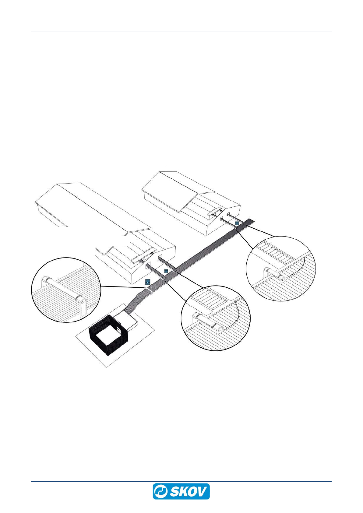
Skov DOL 192 Manual

DOL 192 Egg Counter
Technical User Guide
604537 • 2023-10-13

DOL 192 Egg Counter
2 Technical User Guide
Product and Documentation Changes
SKOV A/S reserves the right to change this document and the product herein described without further notice.
In case of doubt, please contact SKOV A/S.
The date of change appears from the front and back pages.
Note
• All rights belong to SKOV A/S. No part of this manual may be reproduced in any manner whatsoever without
the expressed written permission of SKOV A/S in each case.
• All reasonable efforts have been made to ensure the accuracy of the information contained in this manual.
Should any mistakes or imprecise information occur in spite of this, SKOV A/S would appreciate being noti-
fied thereof.
• Irrespective of the above, SKOV A/S shall not accept any liability with regard to loss or damage caused or
alleged to be caused by reliance on any information contained herein.
• Copyright by SKOV A/S.

DOL 192 Egg Counter
1 Product description ....................................................................................................................................... 4
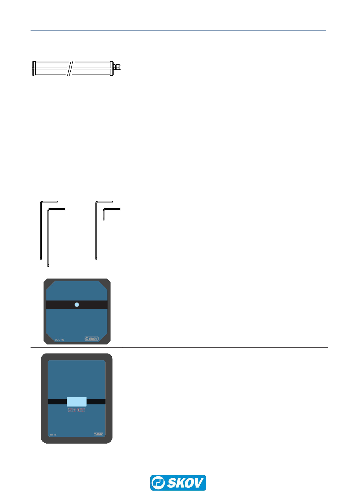
2 Product survey ............................................................................................................................................... 5
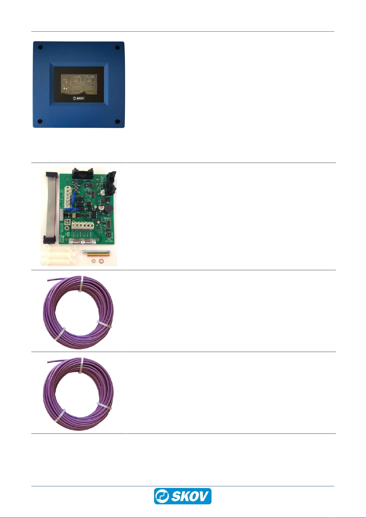
2.1 Accessories................................................................................................................................ 6
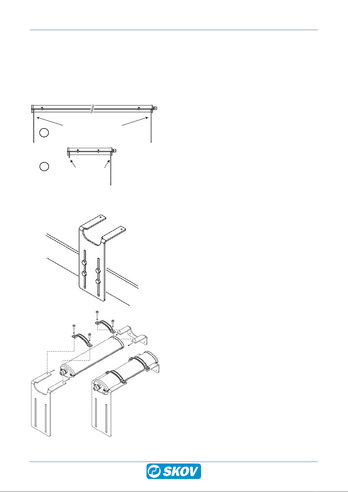
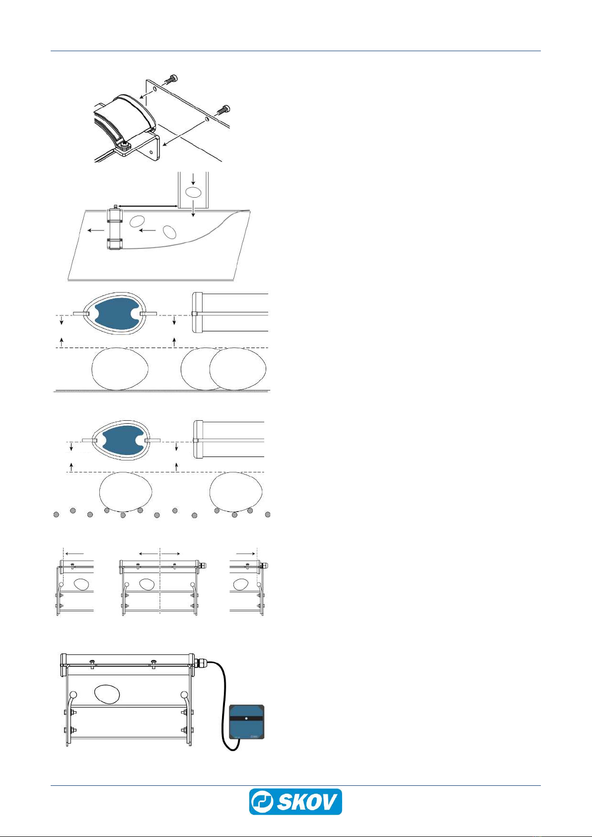
3 Mounting guide............................................................................................................................................... 8
3.1 Recommended tools.................................................................................................................. 8
3.2 Mounting the egg counter......................................................................................................... 9
4 Installation guide.......................................................................................................................................... 11
4.1 Connecting the egg counter to the DOL 192 box ................................................................. 11
4.1.1 Cable diagram egg counter........................................................................................................ 11
4.1.2 DOL 192 box 24 V ..................................................................................................................... 12
4.1.3 DOL 192 box w/display 230V..................................................................................................... 13
4.2 Connecting pulse and standby functions ............................................................................. 14
4.3 DIP switch settings .................................................................................................................. 14
4.4 Choice of egg counter in controller ....................................................................................... 15
4.5 Clock setting DOL 192 box w/display .................................................................................... 16
5 General information about circuit diagrams.............................................................................................. 17
5.1 Color code ................................................................................................................................ 17
5.2 Letter code................................................................................................................................ 17
6 Cable plans and circuit diagrams ............................................................................................................... 18
6.1 Cable plan DOL 192 box 24V 1 egg counter.......................................................................... 18
6.2 Circuit diagram DOL 192 box 24 V 1 egg counter................................................................. 18
6.3 Cable plan DOL 192 box 24 V 2 egg counters....................................................................... 19
6.4 Circuit diagram DOL 192 box 24 V 2 egg counters............................................................... 19
6.5 Cable plan Dol 192 box w/display 230 V ................................................................................ 20
6.6 Circuit diagram DOL 192 box w/display 230 V ...................................................................... 20
7 User Guide .................................................................................................................................................... 21
7.1 Operating DOL 192 box w/display.......................................................................................... 21
8 Maintenance instructions ............................................................................................................................ 22
8.1 Cleaning.................................................................................................................................... 22
8.2 Recycling/Disposal .................................................................................................................. 22
9 Trouble shooting instructions .................................................................................................................... 23
9.1 Error messages LED on DOL 192 box ................................................................................... 23
9.2 Error messages DOL 192 box w/display................................................................................ 23
9.3 Unexpected counting results.................................................................................................. 23
10 Technical data .............................................................................................................................................. 24
10.1 DOL 192 egg counter............................................................................................................... 24
10.2 DOL 192 box ............................................................................................................................. 25
10.3 Maximum number of devices connected to power supply .................................................. 25
10.4 Dimensioned sketch ................................................................................................................ 26
10.4.1 DOL 192 egg counter................................................................................................................. 26
10.4.2 DOL 192 box w/display 230 V f/1 egg counter........................................................................... 26
10.4.3 DOL 192 box 24 V f/2 egg counters........................................................................................... 27
Technical User Guide

DOL 192 Egg Counter
4 Technical User Guide
1 Product description
The DOL 192 egg counter is intended for automatically counting eggs with an egg diameter of 36-55 mm, on a
conveyor belt.
It is designed for touch-free operation, using infrared light. It reduces the risk of eggshell fractures and contami-
nation and ensures an unhampered flow of eggs on the conveyor belt.
DOL 192 egg counter is available in 5 different scan widths (12, 20, 40, 50, and 80 cm) to suit different types of
conveyors.
A connection box with and without display is available.
DOL 192 egg counter has an accuracy of at least 99.5% when correctly fitted.
DOL 192 egg counter 80 cm
DOL 192 egg counter 40 cm
DOL 192 egg counter 20 cm
DOL 192 connection box 24 V
DOL 192 connection box w/display 230V
DOL 192 connection box 24 V
DOL 192 bracket L+L
DOL 192 bracket S+L
DOL 192 bracket S+L
Figure1: Example of egg counter mounting option.

DOL 192 Egg Counter
Technical User Guide 5
2 Product survey
130383 DOL 192 egg counter, 12 cm
Scan width 120 mm
130384 DOL 192 egg counter, 20 cm
Scan width 216 mm
130385 DOL 192 egg counter, 40 cm
Scan width 408 mm
130386 DOL 192 egg counter, 50 cm
Scan width 504 mm
130387 DOL 192 egg counter, 80 cm
Scan width 792 mm
Cable length 2 m
The DOL 192 is suitable for counting eggs on conveyor belts that collect
eggs from multiple longitudinal conveyor belts.
Used for counting eggs with an egg diameter of 36-55 mm.
130388 DOL 192 bracket L+L
130389 DOL 192 bracket S+L
Brackets with clamps and screws are used for mounting the egg counter.
L+L is used for placement above longitudinal conveyor belts.
S+L is used when egg belt guides are applied on longitudinal conveyor
belts.
SKOV A/S does not supply the egg belt guide.
130391 DOL 192 box 24 V f/2 counters
Egg counter connection box that provides data to the production controller.
Up to 2 DOL 192 egg counters can be connected.
Requires external power supply 24 V DC (135752).
130392 DOL 192 box w/display 230 V f/1 counter
Egg counter connection box with a display that provides data to the produc-
tion controller. The number of eggs can be read locally via the display.
You can connect 1 DOL 192 egg counter.

DOL 192 Egg Counter
6 Technical User Guide
2.1 Accessories
135752 Power supply 24V, 2.1A in box
Extra power supply.
Voltage 90 – 264 V
Frequency 47-63 Hz
Power 160 VA/ 80 W
Current 0.7 A
Output
Voltage 24 V +/- 10 %
Current 2.1 A
136470 BlueControl extension box 10RL
Extension box with 1 pcs. I/O module, 10RL 8AI 10RL, type 3.
0-10 V input or DOL 12 input or digital input (8)
0-10 V outputs (8)
Relays (10)
Used when more I/O modules are needed than are available in the standard
hardware.
The inputs can with a jumper be configured individually for either DOL 12,
DI (digital input) for water meters or AI (analog input, 0-10 V).
Includes rubber sleeves and ribbon cable
The controller's standard software/hardware supports 13 I/O modules in to-
tal. BlueControl extension box 10RL counts for 1 module
136471 BlueControl extension box 20RL
Extension box with 2 pcs. I/O module, 10RL 8AI 10RL, type 3.
0-10 V input or DOL 12 input or digital input (16)
0-10 V outputs (16)
Relays (20)
Used when more I/O modules are needed than are available in the standard
hardware.
The inputs can with a jumper be configured individually for either DOL 12,
DI (digital input) for water meters or AI (analog input, 0-10 V).
Includes rubber sleeves and ribbon cable
The controller's standard software/hardware supports 13 I/O modules in to-
tal. BlueControl extension box 20RL counts for 2 modules.

DOL 192 Egg Counter
Technical User Guide 7
130183 DOL 100 digital 8l box
130184 DOL 100 digital 16l box
130191 DOL 100 digital 24l box
130192 DOL 100 digital 32l box
External I/O box for connection of water meter, egg counter, or capacitive
sensor.
The DOL 100 converts the signals into digital signals and transmits them to
the production controller using CAN bus communication.
The standard software/hardware of the BlueControl series supports 13 I/O
modules in total. DOL 100 counts as one module.
0-24 V inputs terminals: 8, 16, 24 or 32.
Is used with the CAN bus module (132245) and a CAN bus cable
(130121-130128).
132245 CAN-bus module
Always use the CAN-bus module when using external CAN bus communi-
cation.
One for each controller.
130121 CAN bus cable 50 m
130125 CAN bus cable 100 m
130126 CAN bus cable 250 m
For indoor use.
Must be used with external units using CAN bus communication.
130123 CAN bus cable UV 50 m
130127 CAN bus cable UV 100 m
130128 CAN bus cable UV 250 m
For outdoor use.
Must be used with external units using CAN bus communication.

DOL 192 Egg Counter
8 Technical User Guide
3 Mounting guide
3.1 Recommended tools
A list of tools recommended for the installation of your egg counter can be seen below.
Topic Description
Cordless drill
Screwdriver bits
Drill kit
Utility knife
Multimeter
Tape measure
Side cutter
Pointed pliers
Screwdriver
Adjustable spanner
Spirit level

DOL 192 Egg Counter
Technical User Guide 9
3.2 Mounting the egg counter
The egg counter is mounted on the bracket directly over the conveyor belt.
For the egg counter to count optimally, place it where the eggs cannot roll or move sideways. Eggs that move
around may be counted more than once.
When the conveyor belt stops, it must not move backward.
A sharp light, especially sunlight and fluorescent light, may affect the accuracy of the egg counter. Place the egg
counter, so it is not exposed to direct (sun)light or protect it from light.
12 - 20 cm
40 - 80 cm
DOL 192 Egg Counter
A
B
This is an example of which brackets can be used.
A: L+L is used for placement above longitudinal conveyor
belts.
B: S+L is used when egg belt guides are applied on longitu-
dinal conveyor belts.
Install the large bracket to the side of the conveyor belt.
Slide the cable end of the egg counter into the bracket.
Slide the opposite bracket (small or large) into the egg
counter.
Attach the large opposite bracket to the other side of the
conveyor belt.
Secure the egg counter to the brackets with clamps and
screws.

DOL 192 Egg Counter
10 Technical User Guide
Mount the egg belt guide to the small bracket.
Mount the opposite end on the conveyor belt.
400 - 500 mm
The distance from the longitudinal conveyor belt to the egg
counter must be approximately 400 to 500 mm, so the eggs
remain stationary before being counted.
30 mm / 1.2" 30 mm / 1.2"
Flat conveyor belt
Based on an egg size of 44 mm, adjust the height of the
bracket so that the distance is 30 mm between the bottom
edge of the bracket and the top of the egg.
Adjust the height of the egg counter when the size of the
egg changes.
30 mm / 1.2" 30 mm / 1.2"
Bar conveyor belt
Based on an egg size of 44 mm, adjust the bracket height
so that the distance is 30 mm between the bottom edge of
the bracket and the top of the egg.
Adjust the height of the egg counter when the size of the
egg changes.
Adjust the egg counter to fit the conveyor belt. Tighten all U-
bolts.
Install the DOL 192 box as close to the egg counter as pos-
sible.
Do not extend the supplied 2-meter cable.

DOL 192 Egg Counter
Technical User Guide 11
4 Installation guide
Installation, servicing and troubleshooting of all electrical equipment must be carried out by quali-
fied personnel in compliance with the applicable national and international standard EN 60204-1
and any other EU standards that are applicable in Europe.
The installation of a power supply isolator is required for each motor and power supply to facilitate
voltage-free work on the electrical equipment. The power supply isolator is not included.
4.1 Connecting the egg counter to the DOL 192 box
4.1.1 Cable diagram egg counter
cable length 2 m

DOL 192 Egg Counter
12 Technical User Guide
4.1.2 DOL 192 box 24 V
Connect egg counter 1 in CON 4 and egg counter 2 in CON 5.

DOL 192 Egg Counter
Technical User Guide 13
4.1.3 DOL 192 box w/display 230V
Connect egg counter in CON 4.

DOL 192 Egg Counter
14 Technical User Guide
4.2 Connecting pulse and standby functions
Pulse:
The egg counter is connected to a production controller as an electrical pulse generator. An electrical pulse is
generated to the output of the egg counter when an egg is detected. The pulse output is an NPN output.
Standby input:
The standby input is activated when the conveyor belt under the egg counter stops. When the standby input is
active, the LED emits an orange light or --/h (display), and the egg counter ceases to count eggs.
• When an NC relay is switched off during conveyor operation, eggs are counted.
• When an NC relay is activated in case the conveyor belt is stopped, eggs are not counted.
Failure to use the standby input may adversely affect the accuracy. The standby input ensures that eggs are
only counted when the conveyor belt is running.
We recommend using the standby input at all times to ensure maximum accuracy.
The standby input is common when there are 2 egg counters installed.
4.3 DIP switch settings
Select how many egg counters are connected to the box.
• DIP switch #7 (OPT 1):
– OFF: When 1 DOL 192 egg counter is connected to a DOL 192 box 24V.
– ON: When 2 DOL 192 egg counters are connected to a DOL 192 box 24V.
Select whether the DOL 192 box uses one pulse per egg or one pulse per five eggs (a maximum of 5 pulses per
second).
• DIP switch #8 (OPT 2):
– OFF: 1 pulse per egg.
– ON: 1 pulse per 5 eggs.
Note that pulse per egg should be set the same way for both the DIP switch and Choice of egg counter in con-
troller [}15].

DOL 192 Egg Counter
Technical User Guide 15
4.4 Choice of egg counter in controller
| Installation | Manual installation | Production | Installation |
Egg counting and select Automatic.
| Installation | Manual installation | Production | Installation |
Egg settings | Egg counters installed.
Enter the number of egg counter to be installed.
| Installation | Manual installation | Production | Installation |
Egg settings | Same pulse for all egg counters.
Enter the number of eggs per pulse.
| Installation | Manual installation | Production | Installation |
Egg settings | Set up eggs per pulse.
Specify the number of eggs per pulse for each egg counter.
Note that pulse per egg is set the same way here and in the DIP-switch
indstillinger [}14].
| Installation | Show connections.
Indicates to which terminals the egg counter should be connected.
Ground terminal/minus terminal clamp for sensor and feedback is not dis-
played.

DOL 192 Egg Counter
16 Technical User Guide
4.5 Clock setting DOL 192 box w/display
The clock must be set to the current time.
Use the up/down arrows to navigate to the clock display.
Time:
• Press arrow to the right. Adjust hours using the up/down arrow.
• Press arrow to the right. Adjust the minutes using the up/down arrow.
• Press Enter to confirm the adjusted time.

DOL 192 Egg Counter
Technical User Guide 17
5 General information about circuit diagrams
Symbols are in accordance with the IEC/EN 60617 standard.
The classification of the symbols ("letter codes") on the symbols is in accordance with the IEC/EN 81346-2 stan-
dard.
Reference designations are in accordance with IEC/EN 81346-1:2001 structuring principles and reference des-
ignations. This standard indicates structured methods for naming electrotechnical systems.
5.1 Color code
Letter Code Color Standard
BK Black
Color coding on wires are in accor-
dance with standard IEC 60757:
Letter codes to identify colors used
on drawings, diagrams, labelling,
etc.:
BN Brown
RD Red
OG Orange
YE Yellow
GN Green
BU Blue (incl. light blue)
VT Violet (purple red)
GY Grey (slate)
WH White
PK Pink
GD Gold
TQ Turquoise
SR Silver
GNYE Green-and-yellow
5.2 Letter code
The letter codes used in accordance with standard IEC/EN61346-2.
-F -K -M -Q -S -T -W
Protective equipment RCCB /
Initial fuse Protective motor
switch
Controller
Contactor
Fan
Motor
Power supply
isolator
Switch Motor con-
troller
Cable

DOL 192 Egg Counter
18 Technical User Guide
6 Cable plans and circuit diagrams
6.1 Cable plan DOL 192 box 24V 1 egg counter
Standby
DOL 192 Egg Counter
DOL 192 box 24 V f/2 egg counters
Controller
Power supply
Supply
6.2 Circuit diagram DOL 192 box 24 V 1 egg counter
Example of terminal number
For correct connection
see the setup menu
Show connections in the controller
Standby switch
ON when conveyor belt is running
Egg counter
Egg counter box 24 V

DOL 192 Egg Counter
Technical User Guide 19
6.3 Cable plan DOL 192 box 24 V 2 egg counters
Standby
DOL 192 egg counter 1
DOL 192 box 24 V f/2 egg counters
Controller
Power supply
DOL 192 egg counter 2
Supply
6.4 Circuit diagram DOL 192 box 24 V 2 egg counters
Example of terminal number
For correct connection
see the setup menu
Show connection in the controller
Standby switch
ON when conveyor belt is running
Egg counter box 24 V
Egg counter

DOL 192 Egg Counter
20 Technical User Guide
6.5 Cable plan Dol 192 box w/display 230 V
Standby
Supply
DOL 192 egg counter
DOL 192 box w/display 230 V f/1 egg counter
Controller
6.6 Circuit diagram DOL 192 box w/display 230 V
Example of terminal number
For correct connection
see the setup menu
Show connection in the controller
Standby switch
ON when conveyor belt is running
Egg counter
Egg counter 230 V
Table of contents
Other Skov Cash Counter manuals
Popular Cash Counter manuals by other brands

Alberici
Alberici HopperOne S11 Operator's manual

Polanik
Polanik T2-LB14 Assembly manual

PRO Intellect Technology
PRO Intellect Technology PRO 57 user manual

Nautilus Hyosung
Nautilus Hyosung MONiMAX7800D Operator's manual

Hengstler
Hengstler tico 731.3 operating instructions

HYOSUNG
HYOSUNG NH-2700T Operator's manual