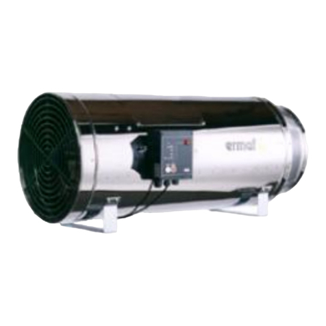
Skov GP14 Manual

2017.12.04 • 612091
Blow Heaters
GP14 /40 /70 /95
Technical User Guide


Blow Heaters
Product and Documentation Changes
SKOV A/S reserves the right to change this document and the product herein described without further notice.
In case of doubt, please contact SKOV A/S.
Date of change appears from the back of this manual.
Safety Instructions and Warnings
The installation must be carried out by an authorized electrician and according to current national and EU
regulations.
A blow heater generates a lot of heat and produces open fire which may result in serious injuries if the
instructions are not observed. For your own safety and for the safety of others, you have to observe the
following rules:
•Do not use the blow heater in case of any sign of damage.
•The blow heater is designed for application together with the connection kit and can only be used
with such a kit.
Before you start using your new blow heater, read the enclosed instructions in order to prevent injury to the
user and damage to the surroundings and the blow heater itself.
Please note that this guide only is a Technical User's Guide. It does not cover the setting of advanced functions
of the blow heaters GP 40 / GP 70 and/or the BCU.
Using gas and gas burners involves the risk of fire, explosion and/or gas poisoning.
Mechanical fitters and technicians connecting the blow heaters to the main gas supply,
disconnect the gas piping and adjust the output of the burner should be trained and
authorised personnel.
Note
•All rights reserved SKOV A/S. No part of this manual may be reproduced in any manner
whatsoever without the expressed written permission of SKOV A/S in each case.
•SKOV A/S has made all reasonable efforts to ensure the accuracy of the information contained in
this manual. Should any mistakes or imprecise information occur in spite of this, SKOV A/S would
appreciate being notified thereof.
•Irrespective of the above, SKOV A/S shall not accept any liability with regard to loss or damage
caused or alleged to be caused by reliance on any information contained herein.
•Copyright 2013 by SKOV A/S.
Check the product as regards defects or damages (e.g. transport damages) prior to initial operation. In case of
defect or damage, please contact SKOV A/S or the nearest distributor.

4 Technical User Guide
Blow Heaters
1MANUALS SUPPLIED BY THE MANUFACTURER .......................................6
2PRODUCT LAYOUT - OVERALL POSITIONING OF COMPONENTS...........7
3METHOD OF OPERATION ..............................................................................8
3.1 BCU. Functional Diagram and Troubleshooting....................................................9
4RECOMMENDED TOOLS..............................................................................10
5WARNINGS AND SYMBOLS.........................................................................10
6POSITIONING OF BLOW HEATERS - DISTANCES ....................................11
7SUSPENSION OF BLOW HEATER...............................................................12
7.1 Blow Heater with standard suspension kit...........................................................12
7.2 Blow Heater at a free but fixed height...................................................................13
7.3 Blow Heater at an adjustable Height.....................................................................14
8SUSPENSION LOAD......................................................................................15
8.1 GP 14........................................................................................................................15
8.2 GP 40 / GP 70 ..........................................................................................................16
8.3 GP 95........................................................................................................................17
9ELECTRIC CONNECTION.............................................................................18
9.1 Connection in Blow heater.....................................................................................18
9.2 Circuit Diagram.......................................................................................................18
10 CHECK TYPE OF GAS ..................................................................................19
11 CONNECTION TO THE GAS GRID...............................................................19

Technical User Guide 5
Blow Heaters
PRODUCT DESCRIPTION
This Technical User's Guide is a supplement to the manuals supplied by the manufacturer of the product.
Manuals are included with the blow heaters. This guide does not replace the manuals supplied by the
manufacturer. Contact SKOV A/S in case of deviations between information in this guide and the manuals
supplied by the manufacturer. As a rule, the manual supplied by the manufacturer of the product is applicable.
This guide shows the variants of blow heaters used by SKOV A/S, includes a short general functional
description and directions for mounting of the blow heater integrated in a ventilation system.
The blow heaters heat up and circulate the housing air by means of the built-in fans. The blow heaters are
direct-fired and can be a supplement to or a replacement for water-based indirect-fired heating systems and are
primarily used for heating in livestock house sections. Direct-fired means that the generation of heat takes place
as a result of direct, open combustion of gas in the house section itself.
Blow heaters can be used as on/off air circulators, when heating is not required.
Figure 1: Principle sketch of blow heater and stir fan.
Blow heater
Air circulator

6 Technical User Guide
Blow Heaters
1 Manuals supplied by the Manufacturer
This guide is a supplement to the manuals supplied by the manufacturer. Among other things, the manual
supplied by the manufacturer describes exactly how to adjust the blow heater and how to troubleshoot.
The manuals supplied by the manufacturer have A4 format and look like this:
Deals with GP 14:
Deals with GP 40 and GP 70:
Deals with GP 95:

Technical User Guide 7
Blow Heaters
2 Product Layout - overall Positioning of Components
Figure 2: Positioning of main components. (For more detailed information please confer the manual supplied by
the manufacturer)
AThe BCU (Burner Control Unit):
A signal from the SKOV climate computer prompts the internal control of the blow heater executing
the safety, start and stop procedures.
BGas combination valve:
The CG10 or CG220 gas valve controls the pressure in the burner, ensures that the supply pressure is
okay plus opens/closes the gas supply.
CConnection to the gas grid. The supply pressure is measured here.
DPiping between the gas combination valve and the burner. The pressure in the burner is measured
here.
EFan/mechanical blower.
FWind gauge.
Check that the fan is running before gas injection is activated and gas is ignited.
B
A
D
C
E
F

8 Technical User Guide
Blow Heaters
3 Method of Operation
The blow heaters are switched on in the same way as all other types of relay-controlled heat sources; i.e. on/off
operation mode - either full capacity or completely closed. The blow heater does not provide modulation as
regards the output.
When heat requirement is registered by the SKOV climate computer, it switches on the blow heaters by
activating the relay assigned to relay-controlled heating. When it operates as air circulator, it is controlled by
the relay for air circulator.
The blow heaters are connected to their own power supply and are permanently provided operating voltage.
Only the start signal itself comes from the SKOV climate computer which is either 24 V AC/DC or 230V.
Each blow heater has its own internal controller - the so-called BCU (Burner Control Unit).
When the blow heater receives a start signal, the BCU runs through the following start-up procedure every time
(see Figure 2):
1. The position of the wind gauge is registered F.
2. The fan is started E.
3. It is checked that the wind gauge Fchanges position. This confirms that the fan works. If the wind
gauge does not change position, the BCU Aterminates the start-up and carries out a troubleshooting
procedure or changes to ALARM mode.
4. The gas supply pressure is checked. If insufficient gas pressure, the BCU (1) terminates the start-up and
carries out a troubleshooting procedure or changes to ALARM mode.
5. Ignition sequence is activated.
6. If sufficient gas pressure, gas vane is turned on B.
7. The ignition sequence is cut off.
8. Ionization current is registered. If a sufficiently high ionization current has not been registered within
5-10 seconds, the BCU terminates the start-up and changes to ALARM mode.
9. If the ionization current is at a sufficient level (5-30 µA), the gas vane remains on until the start signal
from the SKOV climate computer is cut out.
10. When the start signal is cut out, the gas vane is turned off and the burner switches off.
11. The fan continues to run for minimum 10 seconds after the burner is switched off in order to cool down
the blow heater. Subsequently, the fan switches off automatically.
The start-up procedure and the various alarms are described in detail in the manual supplied by the
manufacturer.
The gas is ignited and combusted in a combustion chamber positioned in the middle of the current of air
produced by the fan. This heats up the housing air. During operation, the temperature of the outside surface of
the blow heater does not exceed 45°C.
Apart from the safety functions mentioned above, the BCU currently monitors the blow heater so that it is not
overheating. The BCU Aand the gas combination valve Bare essential safety components on the blow heaters.
For the same reason, the user must not disassemble/repair the gas combination valve and may only to a limited
degree disassemble/repair the BCU.

Technical User Guide 9
Blow Heaters
3.1 BCU. Functional Diagram and Troubleshooting
Table 1: The functional diagram provides a schematic outline of the functions of the BCU.
Also see diagram in the manual concerning systematic troubleshooting.

10 Technical User Guide
Blow Heaters
GENERAL INFORMATION
4 Recommended Tools
The following or equivalent tools are required for servicing blow heaters. Tools are not supplied by SKOV A/S.
Tools and Instruments
Manometer
For adjustment of the pressure in the gas burner,
troubleshooting and service.
1 x 2.5mm Hex screwdriver
For adjustment of the pressure in the gas burner.
1 x PZ2 screwdriver
For the cover of the BCU.
1 x 3,5mm Slotted screwdriver
For electrical connections.
Access to measuring points
SImpact drill
Drill bits, various sizes
6”, 8” and 10” adjustable spanner
For nuts, bolts and gas connections.
35mm hexagonal socket
+ 400mm extension shaft
+ T-handle bar (max. 300mm)
For nozzle exchange.
Pipe wrenches, various sizes
Water spray bottle with soap water
For leakage search.
Table 2: Indispensable tools for servicing blow heaters
5 Warnings and Symbols
This manual uses the following symbols:
Warning of general danger

Technical User Guide 11
Blow Heaters
MOUNTING GUIDE
Before mounting the blow heater check that the ordered parts have been received and that they are in
undamaged condition
6 Positioning of Blow Heaters - Distances
For safety reasons, abide by the following minimum distance requirements:
Figure 3: Distance
In the interest of good air circulation, the distance between the air intake of the blow heater and the wall/house
end must be approx 5m.
If however the distance is shorter, the safety distance of 3m in front of the blow heater should be given the
highest priority.
The spacing between the gas burners depends on the type. Table 3 specifies the minimum and maximum
distances.
Air inlet

12 Technical User Guide
Blow Heaters
7 Suspension of Blow Heater
7.1 Blow Heater with standard suspension kit
All blow heaters come with a standard suspension kit.
Suspension kit
Pos.
Number of
Description
1
4
Eye joiner Ø7 x 40mm
2
4
Chain 0.8m 4 x 32mm DIN 763
1 and 3
8
Snap hook 5mm
Figure 4: Standard suspension kit
80 cm
80 cm
1
2
3

Technical User Guide 13
Blow Heaters
7.2 Blow Heater at a free but fixed height
Number
Article number
Description
2
570914
Fixing rail 20 x 34mm
3
570917
Hammerhead bolt M8 x 30
3
413033
Eye Joiner M8 stainless
6
413042
Wire lock 2-4mm A2
12m
413104
Steel wire 2.0mm stainless
8
530999
Self-cutting stainless screw 6.3 x 25mm
6
419249
Roofing nail 6 x 90mm including washers
3
359065
Snap hook 5x50
Figure 5: Free but fixed height
570917
413033
413042 570914
570914
413042
359065
530999/419249
530999/419249

14 Technical User Guide
Blow Heaters
7.3 Blow Heater at an adjustable Height
Number
Article number
Description
2
570914
Fixing rail 20 x 34mm
5
415091
Pulleys for creep box opening
4
413042
Wire lock 2-4mm A2
1
413210
Crank 80 kg
16m
413104
Steel wire 2.0mm stainless
4
419375
Coach screw Ø6 x 70 A2 DIN571
4
419335
Wall dowel 8 mm
10
530999
Self-cutting stainless screw 6.3 x 25mm
6
419249
Roofing nail 6 x 90mm including washers
5
570917
Hammerhead bolt M8 x 30
5
413033
Eye Joiner M8 stainless
8
359065
Snap hook 5 x 50
Figure 6 Adjustable Height
570917
413033
359065
415091 570914
570914
413210
413042
413042
359065
530999/419249
530999/419249
413104
419375
419335

Technical User Guide 15
Blow Heaters
8 Suspension Load
8.1 GP 14
Weight = 13 kg distributed as follows:
Figure 7: GP 14 weight
SKOV A/S recommends that the load capacity of each suspension point be at least 20 kg.
ADistance between front and rear eye joiner = 41cm
Figure 8: GP 14 distance
Suspension load: 11 kg
Suspension load:
5 kg
A

16 Technical User Guide
Blow Heaters
8.2 GP 40 / GP 70
Weight = 26.8 kg distributed as follows:
Figure 9: GP 40 / GP 70 weight
SKOV A/S recommends that the load capacity of each suspension point be at least 30 kg.
ADistance between the two rear eye joiners = 40cm
BDistance between front and rear eye joiner = 75cm
Figure 10: GP 40 / GP 70 distance
Suspension load: 6-8 kg
Suspension load: 6-8
kg
Suspension load: 17-19
kg
A
B

Technical User Guide 17
Blow Heaters
8.3 GP 95
Weight = 38.4 kg distributed as follows:
Figure 11: GP 95 weight
SKOV A/S recommends that the load capacity of each suspension point be at least 45 kg.
ADistance between the two front or between the two rear eye joiners = 45cm
BDistance between front and rear eye joiner = 74cm
Figure 12: GP 95 distance
Suspension
load:
19 kg
Suspension
load:
8 kg
A
B
Suspension
load:
8 kg
A

18 Technical User Guide
Blow Heaters
INSTALLATION GUIDE
9 Electric Connection
The installation, service and troubleshooting in connection with electrical equipment
must be carried out by specialists in accordance with applicable national rules. In
Europe in accordance with EN 60204-1 and other applicable EU rules.
The installation of a supply isolator is required for each motor and power supply, so
maintenance of electrical equipment can be carried out in a dead environment. Supply
isolator is not supplied by SKOV A/S.
9.1 Connection in Blow heater
Remove the protective cap, loosen the four screws and install the following leads.
Connector 1: Supply, phase
Connector 3: Supply, neutral
Connector PE: Supply, earth
Connector 28: 230 V signal from an external relay to recirculation
Connector 29: 230 V signal from an external relay to heating
Connector 30: 230 V to external relay
9.2 Circuit Diagram
Figure 13: Circuit diagram blow heater
Ex. of terminal number
For correct connection
see the setup menu
Show Installation in Computer

Technical User Guide 19
Blow Heaters
10 Check Type of Gas
It is important to check that the blow heater is operable with the type of gas available on the farm.
Generally, we distinguish between two types of gas:
1. Natural gas. The gas is supplied as a gaseous substance via a branching pipe system - either regionally
or nationally.
2. LPG / Propane Pressurized gas is supplied as liquefied gas - either in standard gas cylinders or in large,
stationary tank installations in the immediate vicinity of the site of consumption.
The energy density is greater in LPG than in natural gas. Therefore, there are fewer and/or smaller holes in the
nozzle of an LPG version compared to a natural gas version. The difference between natural gas and the LPG
versions lies in the nozzle and the factory set gas pressure.
The difference between the nozzles of the various types of blow heaters appears from Table 3.
In addition, a blow heater can be converted into another version by replacing the nozzle and adjusting the
supply pressure (release pressure to the gas pressure switch) and the pressure in the burner.
Adjust the pressure in the burner according to the current type of gas in order to have the full heat rating as well
as optimum utilization of the combustion agent. In order to be able to set the pressure in the burner correctly,
you have to know:
•The density of the gas [kg/m³], i.e. the weight of the gas per m³ in gaseous form.
•The upper heat value = Hs [MJ/m³] or [kWh/m³].
As a rule, the supply company must provide this piece of information on the gas declaration. However, some
supply companies can only provide information about the individual components of the gas as a weight - %. In
the light of this, SKOV A/S can however in exceptional cases calculate the density and the upper heat value.
Confer the manual included by the manufacturer concerning concise directions for adjustment.
11 Connection to the Gas Grid
SKOV does not supply the gas grid itself, i.e. distribution pipe, gas tanks, gas meter, etc.
SKOV supplies a connection kit including 1.5m of flexible tube together with each blow heater.
See Table 4: Product Survey for selection of the correct connection kit for the blow heater in question.

20 Technical User Guide
Blow Heaters
TECHNICAL DATA
Article no.
410138
410130
410133
410135
410139
410131
410132
410134
Type
GP 14 kW,
NG
GP 40 kW,
NG
GP 70 kW,
NG
GP 95 kW,
NG
GP 14 kW,
LPG
GP 40 kW,
LPG
GP 70 kW,
LPG
GP 95 kW,
LPG
Electrical
Setup
Voltage
[V]
230
230
230
230
230
230
230
230
Frequency
[Hz]
50
50
50
50
50
50
50
50
Power
consumption [A]
0.5
1.1
2.0
2.9
0.5
1.1
2.0
2.9
24 V DC signal
(mA)
15
15
15
15
15
15
15
15
Gas
Gas
Natural gas
LPG / Propane
Supply pressure
[mbar]
20-25
37-50
Effect [kW]
14
40
70
95
14
40
70
95
Nozzle:
Number of holes /
Hole size
[mm]
1 / 3.3
12 / 1.8
12 / 2.3
12 / 2.7
1 / 1.9
6 / 1.6
6 / 1.9
12 / 1.7
Consumption
Natural gas LOW
[m³/h]
1.5
3.9
6.8
9.2
Consumption
Natural gas HIGH
[m³/h]
1.5
3.3
5.7
7.8
Consumption
LPG/Propane
[kg/h]
1.1
2.9
5.0
6.8
Connection kit
410157
410156
410158
Connection type
½” internal thread
¾” external thread
6mm hose connection
Mechanics
Output
[m3/h]
1,200
3,900
4,500
6,500
1,200
3,900
4,500
6,500
Distance
Min.- Max.
[m]
5-10
20-40
25-50
20-40
5-10
20-40
25-50
20-40
Max distance
without
air circulator
[m]
7
30
35
30
7
30
35
30
Max distance
with
air circulator
[m]
10
40
50
40
10
40
50
40
Net weight
[kg]
13.0
26.8
38.4
13.0
26.8
38.4
Gross weight
[kg]
13.0
32.1
57.0
13.0
32.1
57.0
Length
[mm]
600
1200
1150
600
1200
1150
Width
[mm]
406
540
580
406
540
580
Height
[mm]
470
442
520
470
442
520
Table 3: Technical data for blow heaters from SKOV A/S
*Note: When using 410158 Connection kit blow heater LPG 1.5m with LPG/Propane, the supply pressure to
the regulator must be between 0.53 and 1.9 bar.
This manual suits for next models
3
Table of contents
Other Skov Heater manuals