Skov DA 4200 Manual

DA 4200 Floor Heating
System
Adapter Kit
Technical User Guide
604539 • 2023-08-31
English For other language variants of this document we refer to:
Español Para otras variantes del idioma de este documento, visite:
Français Pour les versions dans d'autres langues de ce document veuillez consulter:
http://docs.skov.com/1069

DA 4200 Floor Heating System
2 Technical User Guide
Product and Documentation Changes
SKOV A/S reserves the right to change this document and the product herein described without further notice.
In case of doubt, please contact SKOV A/S.
The date of change appears from the front and back pages.
Note
• All rights belong to SKOV A/S. No part of this manual may be reproduced in any manner whatsoever without
the expressed written permission of SKOV A/S in each case.
• All reasonable efforts have been made to ensure the accuracy of the information contained in this manual.
Should any mistakes or imprecise information occur in spite of this, SKOV A/S would appreciate being noti-
fied thereof.
• Irrespective of the above, SKOV A/S shall not accept any liability with regard to loss or damage caused or
alleged to be caused by reliance on any information contained herein.
• Copyright by SKOV A/S.

DA 4200 Floor Heating System
1 Product description ....................................................................................................................................... 4
2 Product survey ............................................................................................................................................... 5
2.1 Floor heating .............................................................................................................................. 5
2.2 Accessories................................................................................................................................ 6
3 Mounting guide............................................................................................................................................... 8
3.1 Recommended tools.................................................................................................................. 8
3.2 Mounting of sandwich screws.................................................................................................. 9
3.3 Mounting of floor heating unit ................................................................................................ 10
3.3.1 Mounting of adapter kit .............................................................................................................. 11
3.3.2 Mounting of manifold.................................................................................................................. 14
3.3.3 Adjusting the manifolds.............................................................................................................. 15
4 Installation guide.......................................................................................................................................... 16
4.1 Electrical connection............................................................................................................... 16
4.2 Settings in controller ............................................................................................................... 16
4.3 General information about circuit diagrams ......................................................................... 17
4.3.1 Power supply isolator................................................................................................................. 17
4.3.2 Letter code ................................................................................................................................. 17
4.4 Cable plan................................................................................................................................. 18
4.5 Circuit diagram......................................................................................................................... 18
5 Maintenance instructions ............................................................................................................................ 19
5.1 Cleaning.................................................................................................................................... 19
5.2 Recycling/Disposal .................................................................................................................. 19
6 Trouble shooting instructions .................................................................................................................... 20
7 Technical data .............................................................................................................................................. 21
7.1 Dimensioned sketch ................................................................................................................ 21
7.1.1 DA 4200 floor heating DN 25 .................................................................................................... 21
7.1.2 DA 4200 floor heating DN 32 .................................................................................................... 22
7.2 Flow diagram............................................................................................................................ 23
Technical User Guide

DA 4200 Floor Heating System
4 Technical User Guide
1 Product description
Floor heating systems are water-based on section level.
Floor heating unit 0-10 V can be controlled via a controller.
The heating system in the individual section typically includes some or all components mentioned below:
Floor heating
Floor heating pipe

DA 4200 Floor Heating System
Technical User Guide 5
2 Product survey
2.1 Floor heating
439378 DA 4200 floor heating unit 15-70 DN 25
Heating unit with adapter kit is used for adjustment of floor heating. Capac-
ity of the floor heating unit is 1800 l/h.
The heating unit 0-10 V for regulation of heating is mounted on a stainless
plate and includes circulation pump, 0-10 V actuator, 3-way control valve,
non-return valve, ball valve and 3 x DOL 12-100C temperature sensors.
2 x DOL 12-100C temperature sensors enable monitoring of flow tempera-
ture and return flow temperature.
1 x DOL 12-100C temperature sensor is used for adjustment of the flow
temperature.
The floor heating unit must be used together with the manifold kit 1+1 to
manifold kit 10+10.
439377 DA 4200 floor heating floor heating unit 25-125 DN 32
Heating unit with adapter kit is used for adjustment of floor heating. Capac-
ity of the floor heating unit is 4500 l/h.
The heating unit 0-10 V for regulation of heating is mounted on a stainless
plate and includes circulation pump, 0-10 V actuator, 3-way control valve,
non-return valve, ball valve and 3 x DOL 12-100C temperature sensors.
2 x DOL 12-100C temperature sensors enable monitoring of flow tempera-
ture and return flow temperature.
1 x DOL 12-100C temperature sensor is used for adjustment of the flow
temperature.
Use 1 heating unit per house/section.
The floor heating unit must be used together with the manifold kit 1+1 to
manifold kit 10+10.

DA 4200 Floor Heating System
6 Technical User Guide
439561 DA 4200 floor heating manifold kit 1+1
439562 DA 4200 floor heating manifold kit 2+2
439563 DA 4200 floor heating manifold kit 3+3
439564 DA 4200 floor heating manifold kit 4+4
439565 DA 4200 floor heating manifold kit 5+5
439566 DA 4200 floor heating manifold kit 6+6
439567 DA 4200 floor heating manifold kit 7+7
439568 DA 4200 floor heating manifold kit 8+8
439569 DA 4200 floor heating manifold kit 9+9
439570 DA 4200 floor heating manifold kit 10+10
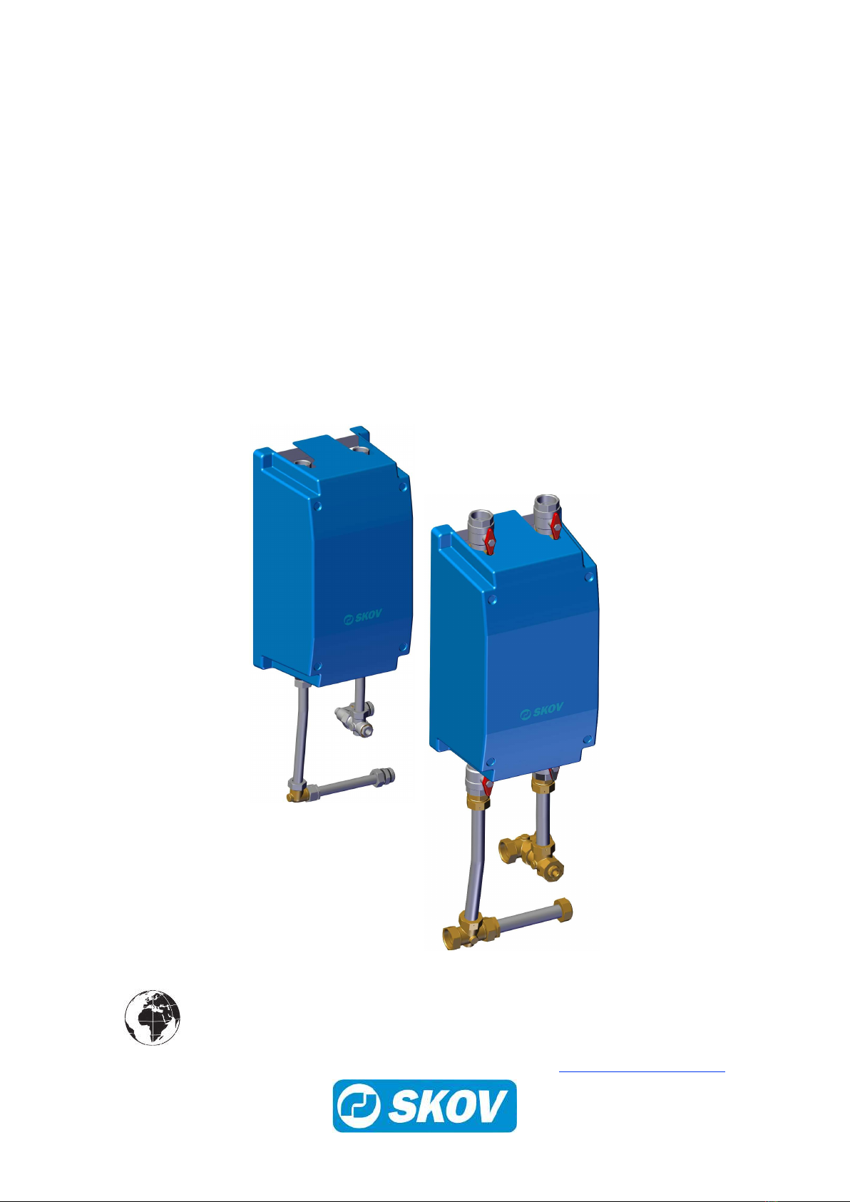
The manifold kit with bracket is used together with the floor heating unit
mentioned above.
The figures specify how many supply flows + return flows can be con-
nected. Each floor heating circuit is equipped with supply and return flow;
e.g.,4 floor heating circuits thus require a manifold kit 4+4.
Is supplied complete with connection set and automatic air vent.
2.2 Accessories
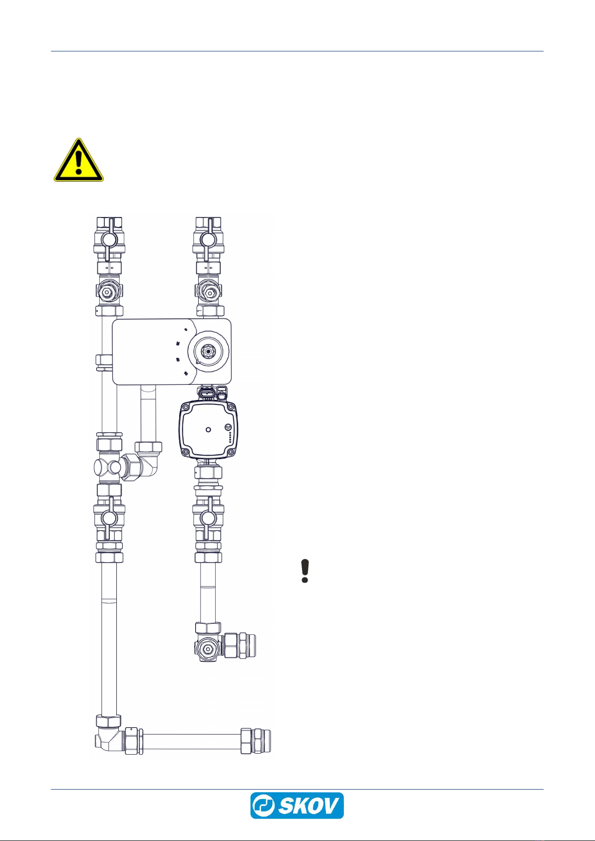
439304 DA 4200 SmartHeat kit DN 25
DA 4200 SmartHeat kit is an add-on that includes a flow sensor and a soft-
ware extension of the controller. SmartHeat kit is used together with DA
4200 room heating/floor heating units DN 25.
After updating and mounting of a flow sensor, the controller can measure
water flow and flow and return temperatures to a house/section. Based on
these recordings, the controller and FarmOnline can calculate and record
the instantaneous heat consumption in kilowatts (kW) and the number of
used kilowatt-hours (kWh) for the current house/section.
The controller generates an alarm if the water flow is too low and if the flow
temperature is too low.
The kit includes flow sensor and USB stick with SmartHeat software.
The SmartHeat software can only be installed on controllers with software
version 8.0 or later.
439305 DA 4200 SmartHeat kit DN 32
DA 4200 SmartHeat kit is an add-on that includes a flow sensor and a soft-
ware extension of the controller. SmartHeat kit is used together with DA
4200 room heating/floor heating units DN 32.
After updating and mounting of a flow sensor, the controller can measure
water flow and flow and return temperatures to a house/section. Based on
these recordings, the controller and FarmOnline can calculate and record
the instantaneous heat consumption in kilowatts (kW) and the number of
used kilowatt-hours (kWh) for the current house/section.
The controller generates an alarm if the water flow is too low and if the flow
temperature is too low.
The kit includes flow sensor and USB stick with SmartHeat software.
The SmartHeat software can only be installed on controllers with software
version 8.0 or later.

DA 4200 Floor Heating System
Technical User Guide 7
439312 DA 4200 thermometer kit ø63 mm
The DA 4200 thermometer kit ø63 mm is used for reading the flow and re-
turn temperature in heating units that are not controlled by a BlueControl
controller.
439471 Floor h. pipe 20mmPn6 incl./oxygen b.120Mtr./rl. 95gr
439476 Floor h. pipe 20mmPn6 incl./oxygen b. 240Mtr./rl. 95gr
439491 Floor h. pipe 20mmPn6 incl./oxygen b. 480 Mtr./rl.95gr
Floor heating pipes for laying and casting in concrete floor.
439975 Tubolit pipe coil 22mm 13mm Insulation 2m
Foam insulation for insulation of floor heating pipe in areas where there is
no requirement for heating of floor/heat loss. E.g. passages or under the
sows in the farrowing sections.
439940 Bending fittings T/pex pipe 20mm
Bracket for fixing bends of the floor heating pipe.
Bending radius = 150mm.
Secures the bend in a 90° position and prevents breakage of the pipe.
439995 Flashing for floor heating – start
Protection rail for floor heating pipes above floor level.
Use one as shield of up to two circuits (up to 2+2).
439996 Flashing for floor heating - next
Is used together with 439995.
Use one per commenced two circuits, in addition to the two circuits which
are covered by the start module.

DA 4200 Floor Heating System
8 Technical User Guide
3 Mounting guide
Check that the ordered parts are present and undamaged before starting assembly. Please read through the
entire guide before starting assembly and fitting.
3.1 Recommended tools
Below is a list of tools recommended for assembly.
Topic Description
Screwdriver set
Utility knife
Marker pen
Tape measure
Hacksaw
Pipe wrench
Side cutter
Impact drill
Drill kit
Adjustable spanner
Water pump pliers
Spirit level

DA 4200 Floor Heating System
Technical User Guide 9
3.2 Mounting of sandwich screws
To ensure that the screw makes the right thickening and the best possible thread on the back, the correct hole
must be drilled first and the screwing must be done with the correct momentum depending on the thickness of
the metal in the sandwich panel.
Diameter of
screw [mm]
Thickness of metal in
sandwich panel
[mm]
Size of holes in
sandwich panel
[mm]
Tightness
torque
[Nm]
5
0.63 - 0.75 ø3.8 2.5
0.75 - 0.88 ø4.1 3.0
0.88 - 1.00 ø4.2 3.5
1.00 - 1.25 ø4.3 3.5
1.25 - 1.50 ø4.4 4.0

DA 4200 Floor Heating System
10 Technical User Guide
3.3 Mounting of floor heating unit
Use packing twine and joint paste when connecting the floor heating unit.
Floor heating pipes must be protected by the flashing for floor heating.
The installation must be carried out by a specialist and according to current national and EU regulations.
Flush supply pipes before connecting them.
Before start-up, fill up the system with water.
Distribution system/heat source
Return flow Supply flow
Return flow
House
(E) (E)
(F)
(F)
(A)
(B)
(D)
(E) (E)
(C)
(G)
Supply flow
(A) 3-way control valve
(B) Actuator 0-10 V
(C) Circulation pump
(D) Non-return valve
(E) Ball valve
(F) DOL 12-100C temperature sensor
(G) DOL 12-100C temperature sensor (control)
Mount the floor heating unit on the wall using 4
screws.
Make sure that the back plate is level and does not
tilt.

DA 4200 Floor Heating System
Technical User Guide 11
3.3.1 Mounting of adapter kit
Mount the connecting piece on the ball valve.
Mount the gasket and the short bended pipe.
Mount the gasket and the sensor pocket.
Mount the gasket and the pipe angle.

DA 4200 Floor Heating System
12 Technical User Guide
Mount the connecting piece on the ball valve.
Mount the gasket and the long bended pipe.
Mount the gasket and the pipe angle.

DA 4200 Floor Heating System
Technical User Guide 13
Mount the gasket and the short straight pipe.
Mount the DOL 12-100C temperature sensor in the
sensor pocket.

DA 4200 Floor Heating System
14 Technical User Guide
3.3.2 Mounting of manifold
Make sure to use packing twine and joint paste
when mounting the connecting piece on the manifold.
Mount the connecting piece on the manifold
Mount the gasket and the manifold with connecting
piece.
Mount the bracket for manifold on the wall.
Mount the bracket on the manifold.

DA 4200 Floor Heating System
Technical User Guide 15
3.3.3 Adjusting the manifolds
LONGEST FLOOR HEATING CIRCUIT
OTHER CIRCUITS
1. Open the longest circuit completely.
2. Select the column containing the longest circuit.
3. Find the row for the circuit to be adjusted.
4. Read in the column for the longest circuit, how many rotations the circuit should be set to.
Example:
Longest circuit = 80 m
Circuit 2 = 50 m
Circuit 3 = 20 m
In the column for 80 m and the row for 50 m, the cell with setting for circuit 2 to states 1.4 revolutions.
In the column for 80 m and the row for 20 m, the cell with setting for circuit 3 to states 0.7 revolutions.
LONGEST FLOOR HEATING CIRCUIT
OTHER CIRCUITS

DA 4200 Floor Heating System
16 Technical User Guide
4 Installation guide
4.1 Electrical connection
Installation, servicing and troubleshooting of all electrical equipment must be carried out by quali-
fied personnel in compliance with the applicable national and international standard EN 60204-1
and any other EU standards that are applicable in Europe.
The installation of a power supply isolator is required for each motor and power supply to facilitate
voltage-free work on the electrical equipment. The power supply isolator is not included.
4.2 Settings in controller
Menu button | Settings | Installation | Manual
installation | Climate | Floor heating
Select 0-10 V - With sensor.
Select DOL 12.
Select DA 4200 heat monitoring.
Menu button | Setings | Installation | Show
connection
Example of terminal connection.
Floor heating B3 = 0-10 V analog out.
Floor heating control temperature B7 = 0-10 V analog
in signal from sensor.
DA 4200 floor heating forward temperature B20 =
0-10 V analog in signal from supply flow.
DA 4200 floor heating return temperature B18 = 0-10
V analog in signal from return flow.
Menu button | Settings | Service | Climate |
Heating | Floor heating
Check the voltage.
0 % open = 2.1 V
100 % open = 9.2 V

DA 4200 Floor Heating System
Technical User Guide 17
Operation | Climate equipment card | Floor
heaters.
Shown here is:
Forward temperature in °C
Return temperature in °C
Control temperature in °C
4.3 General information about circuit diagrams
Symbols are in accordance with the IEC/EN 60617 standard.
The classification of the symbols ("letter codes") on the symbols is in accordance with the IEC/EN 81346-2 stan-
dard.
Reference designations are in accordance with IEC/EN 81346-1:2001 structuring principles and reference des-
ignations. This standard indicates structured methods for naming electrotechnical systems.
4.3.1 Power supply isolator
Power supply isolator
The installation of a power supply isolator is required for each motor and
motor control.
4.3.2 Letter code
The letter codes used in accordance with standard IEC/EN61346-2.
-F -K -M -Q -S -T -W
Protective equipment RCCB /
Initial fuse Protective motor
switch
Controller
Contactor
Fan
Motor
Power supply
isolator
Switch Motor con-
troller
Cable

DA 4200 Floor Heating System
18 Technical User Guide
4.4 Cable plan
Controller
Floor heating unit
Power supply isolator
Connection box
Can possibly carried in the same cable
Connection box
4.5 Circuit diagram
0-10 V actuatorDOL 12
Supply flow
DOL 12
Return flow
Circulation pump
Example of terminal number
For correct connection
see the setup menu
Show connection in the controller
Connection box
DOL 12 control
temperature
Possibly external supply
+24V0V
Connection box

DA 4200 Floor Heating System
Technical User Guide 19
5 Maintenance instructions
5.1 Cleaning
Be aware that the finned tubes must be cold before cleaning because the dirt would otherwise get
stuck on them.
Clean the product with a cloth that has been wrung out almost dry in water and avoid using:
• high-pressure cleaner
• solvents
• corrosive/caustic agents
5.2 Recycling/Disposal
Products suitable for recycling are marked with a pictogram.
It must be possible for customers to deliver the products to local collection sites/recycling stations in accordance
with local instructions. The recycling station will then arrange for further transport to a certified plant for reuse,
recovery and recycling.

DA 4200 Floor Heating System
20 Technical User Guide
6 Trouble shooting instructions
Symptom Cause Solution
No heat Heat source defective. Check the reason for the defect.
Ball valve closed. Open the ball valve.
Defective circulation pump. Call SKOV-service or a local
plumber/electrician for replacement.
The system lacks water. Fill up with water.
Supply flow temperature set incor-
rectly.
Adjust to correct temperature.
defective actuator. Call SKOV-service or a local electri-
cian for replacement.
Heating does not turn off. Lacks signal from controller or defec-
tive actuator
Call SKOV-service or local plumber/
electrician for replacement.
The temperature rises slowly. The heating system has not reached
maximum capacity.
Check out why the heating system
does not give off heat.
The house is very cold at start-up. Give the heating system time to
warm up the cold house.
Sensor alarm Defective sensor. Check the connections to the sen-
sors or mount a new sensor.
Other manuals for DA 4200
2
Table of contents
Other Skov Heating System manuals
Popular Heating System manuals by other brands

Bryant
Bryant Legacy 674D installation instructions

Hitachi
Hitachi UTOPIA R32 Series Installation & operation manual

Toyotomi
Toyotomi OM-22 Type A Installation and operation instructions

Salda
Salda RIS 700PE EKO 3.0 Technical manual

BWT
BWT AQA therm HFB-1717 BA Installation and operating instructions

Valsir
Valsir ARIA EVO V Series manual