Skov DA 4200 Manual

DA 4200 Heating System
Technical User Guide
604538 • 2023-11-09

DA 4200 Heating System
2 Technical User Guide
Product and Documentation Changes
SKOV A/S reserves the right to change this document and the product herein described without further notice.
In case of doubt, please contact SKOV A/S.
The date of change appears from the front and back pages.
Note
• All rights belong to SKOV A/S. No part of this manual may be reproduced in any manner whatsoever without
the expressed written permission of SKOV A/S in each case.
• All reasonable efforts have been made to ensure the accuracy of the information contained in this manual.
Should any mistakes or imprecise information occur in spite of this, SKOV A/S would appreciate being noti-
fied thereof.
• Irrespective of the above, SKOV A/S shall not accept any liability with regard to loss or damage caused or
alleged to be caused by reliance on any information contained herein.
• Copyright by SKOV A/S.

DA 4200 Heating System
1 Product description ....................................................................................................................................... 5
2 Product survey ............................................................................................................................................... 6
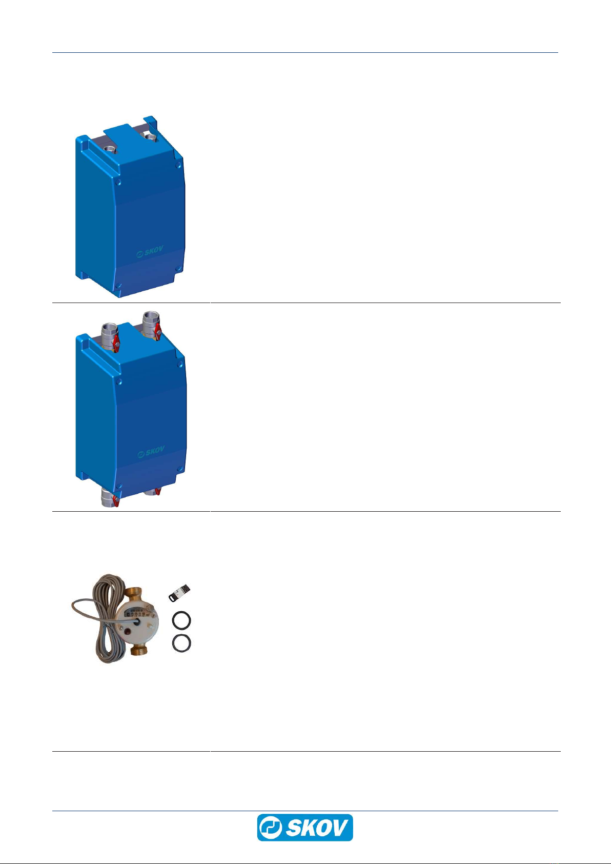
2.1 Regulation .................................................................................................................................. 6
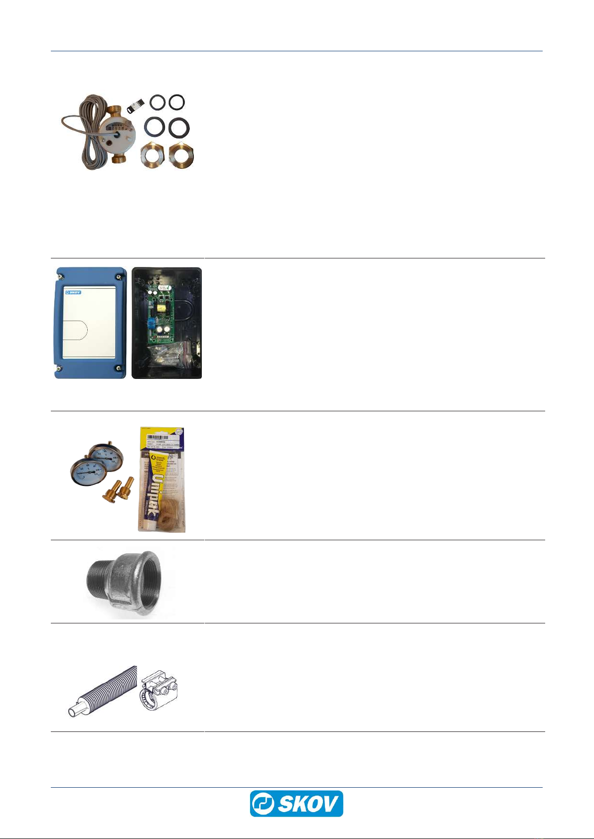
2.1.1 Accessories.................................................................................................................................. 6
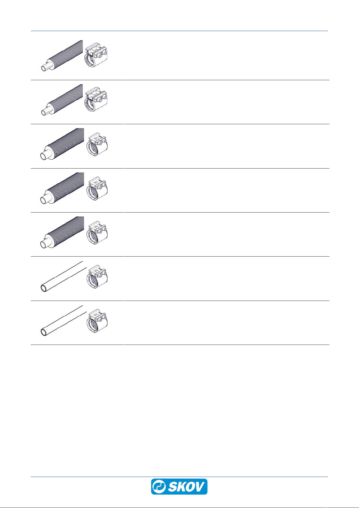
2.2 Pipe ............................................................................................................................................. 7
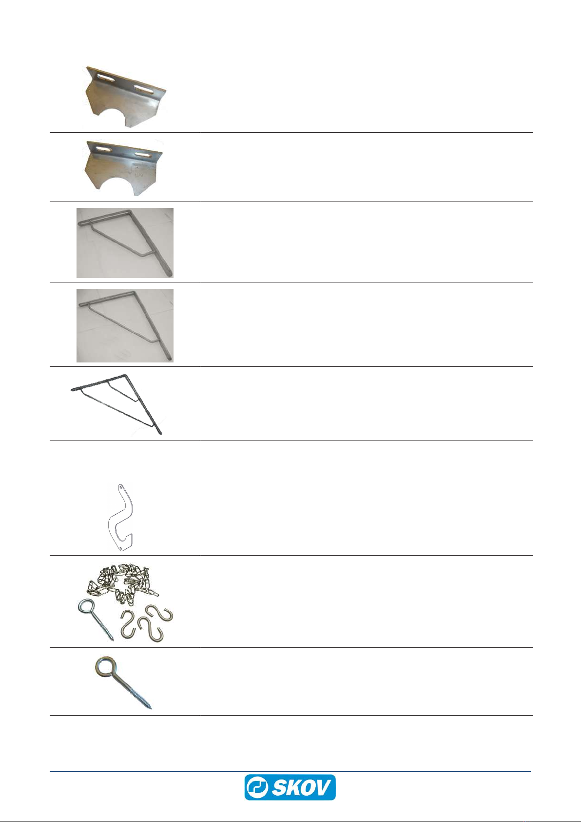
2.3 Mounting on wall and rafter ...................................................................................................... 9
2.4 Mounting on ceiling ................................................................................................................. 10
2.5 Mounting set............................................................................................................................. 11
2.6 Expansion, fittings etc............................................................................................................. 15
2.7 Additional ................................................................................................................................. 18
3 Mounting guide............................................................................................................................................. 19
3.1 Recommended tools................................................................................................................ 19
3.2 Mounting of sandwich screws................................................................................................ 20
3.3 Mounting of heating unit ......................................................................................................... 21
3.4 Finned tubes/smooth tubes .................................................................................................... 22
3.4.1 Placement .................................................................................................................................. 22
3.4.2 Support/Fixing............................................................................................................................ 23
3.4.2.1 Wall mounting on smooth-faced solid walls ............................................................................... 23
3.4.2.2 Wall mounting on sandwich panel ............................................................................................. 24
3.4.2.3 Wall mounting on walls with obstacles....................................................................................... 26
3.4.2.4 Mounting on ceiling .................................................................................................................... 27
3.4.3 Connecting pipes ....................................................................................................................... 28
3.4.4 Mounting pipe coupling on pipes ............................................................................................... 29
3.4.4.1 Expansion .................................................................................................................................. 31
3.4.4.2 Shortening of smooth pipes ....................................................................................................... 31
4 Installation guide.......................................................................................................................................... 32
4.1 Electrical connection............................................................................................................... 32
4.2 Settings in controller ............................................................................................................... 32
4.3 General information about circuit diagrams ......................................................................... 33
4.3.1 Power supply isolator................................................................................................................. 33
4.3.2 Letter code ................................................................................................................................. 33
4.4 Cable plans and circuit diagrams........................................................................................... 34
4.4.1 Cable plans ................................................................................................................................ 34
4.4.2 Circuit diagram........................................................................................................................... 34
4.5 Actuator .................................................................................................................................... 35
4.6 3-way control valve.................................................................................................................. 35
4.7 Setup of recirculation pump ................................................................................................... 36
4.7.1 Circulation pump UMP3 ............................................................................................................. 36
4.7.2 Circulation pump UMPXL........................................................................................................... 37
5 Maintenance instructions ............................................................................................................................ 38
5.1 Cleaning.................................................................................................................................... 38
5.1.1 Circulation pump, actuator and solenoid valve .......................................................................... 38
5.1.2 Finned tubes .............................................................................................................................. 38
5.2 Recycling/Disposal .................................................................................................................. 38
6 Trouble shooting instructions .................................................................................................................... 39
7 Service and maintenance of system .......................................................................................................... 40
8 Technical data .............................................................................................................................................. 42
8.1 Room heating unit ................................................................................................................... 42
Technical User Guide

DA 4200 Heating System
Technical User Guide
8.1.1 Performance diagram for pumps ............................................................................................... 43
8.1.2 Flow diagram ............................................................................................................................. 44
8.1.3 Dimensioned sketch................................................................................................................... 45
8.1.3.1 DA 4200 heating unit DN 25 ..................................................................................................... 45
8.1.3.2 DA 4200 heating unit DN 32 ..................................................................................................... 46
8.2 Actuator .................................................................................................................................... 47
8.3 Finned tubes............................................................................................................................. 48
8.3.1 Dimensioned sketch................................................................................................................... 48
8.4 Pipe coupling ........................................................................................................................... 48
8.5 Heat exchanger ........................................................................................................................ 48
8.5.1 Flow diagram ............................................................................................................................. 49
8.5.2 Dimensioned sketch................................................................................................................... 49
9 Enclosure ...................................................................................................................................................... 50
9.1 Replacement table ................................................................................................................... 50

DA 4200 Heating System
Technical User Guide 5
1 Product description
Heating system for at livestock house. The systems are water-based heating systems at section level. The com-
ponents are of a very high quality and they are well suited for a harsh house environment.
The heating unit is controlled via a controller.
The heating system in the individual section typically includes some or all components mentioned below:
• Heating unit (heat control/mixing loop) for room heating.
• Heat sources for room heating, finned tubes/smooth pipes.
• Components for pipe system, supports, fittings, air vents, insulation, etc.
Automatic air
vent
Room heating unit
Mounting set
Bracket
Rail for sandwich
panel
Automatic air
vent
House heater
Smooth pipes
Finned tubes
Pipe coupling

DA 4200 Heating System
6 Technical User Guide
2 Product survey
2.1 Regulation
439373 DA 4200 heating unit 15-70 450 DN 25
439374 DA 4200 heating unit 15-70 720 DN 25
439370 DA 4200 heating unit 15-70 1120 DN 25
439371 DA 4200 heating unit 15-70 1800 DN 25
439372 DA 4200 heating unit 15-70 2800 DN 25
The heating unit 0-10 V for regulation of heating is mounted on a stainless
plate and includes circulation pump, 0-10 V actuator, 3-way control valve,
non-return valve, ball valve and 2 x DOL 12-100C temperature sensors.
The DOL 12-100C temperature sensors enable monitoring of flow tempera-
ture and return flow temperatures in the controller.
Use 1 heating unit per house/section.
439369 DA 4200 heating unit 25-125 4500 DN 32
The heating unit 0-10 V for regulation of heating is mounted on a stainless
plate and includes circulation pump, 0-10 V actuator, 3-way control valve,
non-return valve, ball valve and 2 x DOL 12-100C temperature sensors.
The DOL 12-100C temperature sensors enable monitoring of flow tempera-
ture and return flow temperatures in the controller.
Use 1 heating unit per house/section.
2.1.1 Accessories
439304 DA 4200 SmartHeat kit DN 25
DA 4200 SmartHeat kit is an add-on that includes a flow sensor and a soft-
ware extension of the controller. SmartHeat kit is used together with DA
4200 room heating/floor heating units DN 25.
After updating and mounting of a flow sensor, the controller can measure
water flow and flow and return temperatures to a house/section. Based on
these recordings, the controller and FarmOnline can calculate and record
the instantaneous heat consumption in kilowatts (kW) and the number of
used kilowatt-hours (kWh) for the current house/section.
The controller generates an alarm if the water flow is too low and if the flow
temperature is too low.
The kit includes flow sensor and USB stick with SmartHeat software.
The SmartHeat software can only be installed on controllers with software
version 8.0 or later.

DA 4200 Heating System
Technical User Guide 7
439305 DA 4200 SmartHeat kit DN 32
DA 4200 SmartHeat kit is an add-on that includes a flow sensor and a soft-
ware extension of the controller. SmartHeat kit is used together with DA
4200 room heating/floor heating units DN 32.
After updating and mounting of a flow sensor, the controller can measure
water flow and flow and return temperatures to a house/section. Based on
these recordings, the controller and FarmOnline can calculate and record
the instantaneous heat consumption in kilowatts (kW) and the number of
used kilowatt-hours (kWh) for the current house/section.
The controller generates an alarm if the water flow is too low and if the flow
temperature is too low.
The kit includes flow sensor and USB stick with SmartHeat software.
The SmartHeat software can only be installed on controllers with software
version 8.0 or later.
135752 Power supply 24V, 2.1A in box
An external power supply is used if the current consumption of the chosen
24 V components exceeds 0.8 A, as the maximum supply of the internal
controller's power supply is 0.8 A.
Voltage 90–264 V
Frequency 47-63 Hz
Power 160 VA/80 W
Current 0.7 A
Output
Voltage 24 V +/- 10 %
Current 2.1 A
439312 DA 4200 thermometer kit ø63 mm
The DA 4200 thermometer kit ø63 mm is used for reading the flow and re-
turn temperature in heating units that are not controlled by a BlueControl
controller.
570746 Sleeve G. 1.1/2 - 1.1/4 Sleeve-Nipple
The galvanized sleeve is used at transition from DN 32 (1¼) heating unit to
(1½) pipe.
2.2 Pipe
439411 Spiraflex 1" 1.12 m G w/pipe coupling
Includes:
1 x 439421 Spiraflex 1" 1.12 m G f/pipe coupling
1 x 439408 Pipe coupling 1"

DA 4200 Heating System
8 Technical User Guide
439412 Spiraflex 1" 2.8 m G w/pipe coupling
Includes:
1 x 439422 Spiraflex 1" 2.8 m G f/pipe coupling
1 x 439408 Pipe coupling 1"
439413 Spiraflex 1" 5.6 m G w/pipe coupling
Includes:
1 x 439423 Spiraflex 1" 5.6 m G f/pipe coupling
1 x 439408 Pipe coupling 1"
439414 Spiraflex 1½" 1.12 m G w/pipe coupling
Includes:
1 x 439424 Spiraflex 1½" 1.12 m G f/pipe coupling
1 x 439409 Pipe coupling 1½"
439415 Spiraflex 1½" 2.8 m G w/pipe coupling
Includes:
1 x 439425 Spiraflex 1½" 2.8 m G f/pipe coupling
1 x 439409 Pipe coupling 1½"
439416 Spiraflex 1½" 5.6 m G w/pipe coupling
Includes:
1 x 439426 Spiraflex 1½" 5.6 m G f/pipe coupling
1 x 439409 Pipe coupling 1½"
439431 Welded tube 1" 5.6 m galv. w/pipe coupling
Includes:
1 x 439451 Welded tube 1" 2.3 mm 5,6 m galv.
1 x 439408 Pipe coupling 1"
439441 Welded tube 1½" 5.6 m galv. w/pipe coupling
Includes:
1 x 439461 Welded tube 1½" 2.3 mm 5,6 m galv.
1 x 439408 Pipe coupling 1½"

DA 4200 Heating System
Technical User Guide 9
2.3 Mounting on wall and rafter
439401 Rail for sandwich panel f/1-suspension
Includes:
1 x 504787 Rail for sandwich panel f/1-suspension
3 x 351582 Tapping screw 5x16 flange TX25 ZnNi spec.
439402 Rail for sandwich panel f/2-suspension
Includes:
1 x 504788 Rail for sandwich panel f/2-suspension
6 x 351582 Tapping screw 5x16 flange TX25 ZnNi spec.
439403 Wall mount bracket 1" and 1½" 1-tube
439404 Wall mount bracket 1" and 1½" 2-tube
439406 Screw kit for suspension 1" and 1½"
Includes:
2 x 570894 Hex wood screw 8x60 flange TX30 FZB
2 x 419336 Rawlplug 10 mm
439997 Concrete rafter bracket f. 1½” 2-pipe A2

DA 4200 Heating System
10 Technical User Guide
439929 Top bracket 1" 1 pipe AISI304
439920 Top bracket 1½" 1 pipe AISI304
439053 Shelf bracket 25x35cm HG incl. cross braces
439054 Shelf bracket 35x45cm HG incl. cross braces
439050 Shelf bracket 45x60cm HG incl. 2-cross braces
2.4 Mounting on ceiling
439405 Ceiling bracket 1" and 1½" 1-pipe
439407 Screw kit for ceiling bracket 1" and 1½"
Includes:
1 x 540053 Stainless chain 4x32 mm DIN 763
3 x 439817 S-hook, 6x60, A4
1 x 419326 Coach eye screw 8x80 FZB
419326 Coach eye screw 8x80 FZB

DA 4200 Heating System
Technical User Guide 11
439817 S-hook, 6x60, A4
540053 Stainless chain 4x32 mm DIN 763
352510 Anchor screw 6.3x64/M10 E16 TX30 A2
Used when mounting in steel constructions, where items with M10 threads
can subsequently be mounted.
During mounting, the following holes are pre-drilled:
2.0 – 4.9 mm steel = pre-drill a 5.3 mm hole.
5.0 – 6.9 mm steel = pre-drill a 5.5 mm hole.
≥ 7.0 mm steel = pre-drill a 5.7 mm hole.
2.5 Mounting set
If smooth tubes are inserted between the finned tubes and they are less than 5.6 meters long, the use of 1
pipe coupling is to be anticipated.
439484 1" Room heating mounting set no. 1
Finned tubes in 1 row in 1 side.
Finned tubes in 2 rows in 1 side.
If the tube lengths exceed 35 meters, an expansion is inserted.
Number of wall fittings = the length of the livestock house / 2.
Requires application of finned and smooth tubes with pipe coupling.
Includes:
2 x 439459 Angle universal f/pipe connection 1" gal
1 x 439455 U-bend 150 mm f/pipe coupling 1" galv.
6 x 439408 Pipe coupling 1"
1 x 570013 Nipple galv. 1" - 200 mm

DA 4200 Heating System
12 Technical User Guide
439485 1" Room heating mounting set no. 2
Finned tubes in 1 row in 2 sides.
Smooth tubes above the door at 2 ends.
If the tube lengths exceed 35 meters, an expansion is inserted.
Number of wall brackets = the length of the livestock house + the width of
the livestock house.
Requires application of finned and smooth tubes with pipe coupling.
Includes:
2 x 439459 Angle universal f/pipe connection 1" galv.
10 x 439453 Elbow f/pipe coupling 90° 1" galv.
3 x 439456 Elbow f/bleeder f/pipe coupling 1" galv.
30 x 439408 Pipe coupling 1"
1 x 570013 Nipple galv. 1" - 200 mm
3 x 439941 Aut. air vent 1/2"
439487 1" Room heating mounting set no. 3
Finned tubes in 2 rows in 2 sides.
Smooth tubes above the door at 1 end.
If the tube lengths exceed 35 meters, an expansion is inserted.
Number of wall brackets = the length of the livestock house + the width of
the livestock house.
Requires application of finned and smooth tubes with pipe coupling.
Includes:
2 x 439459 Angle universal f/pipe connection 1" gal
6 x 439453 Elbow f/pipe coupling 90° 1" galv.
1 x 439455 U-bend 150 mm f/pipe coupling 1" galv.
2 x 439456 Elbow f/bleeder f/pipe coupling 1" galv.
24 x 439408 Pipe coupling 1"
1 x 570013 Nipple galv. 1" - 200 mm
2 x 439941 Aut. air vent 1/2"
439489 1" Room heating mounting set no. 4
Smooth tubes above the door/gate.
Number of wall brackets = depending on the size of the door/gate.
If brackets for 2 pipes are used 2 mounting sets are required.
Requires application of finned and smooth tubes with pipe coupling.
Includes:
3 x 439453 Elbow f/pipe coupling 90° 1" galv.
1 x 439456 Elbow f/bleeder f/pipe coupling 1" galv.
8 x 439408 Pipe coupling 1"
1 x 439941 Aut. air vent 1/2"

DA 4200 Heating System
Technical User Guide 13
439494 1½" Room heating mounting set no. 1
Finned tubes in 1 row in 1 side.
Finned tubes in 2 rows in 1 side.
If the tube lengths exceed 35 meters, an expansion is inserted.
Number of wall fittings = the length of the livestock house / 2.
Requires application of finned and smooth tubes with pipe coupling.
Includes:
2 x 439469 Angle universal f/pipe connection 1½" galv.
1 x 439465 U-bend 150 mm f/pipe coupling 1½" galv.
6 x 439409 Pipe coupling 1½".
2 x 439915 Red. sleeve G.1½ - 1" sleeve-nipple
1 x 570014 Nipple galv. 1½"- 200 mm
439495 1½" Room heating mounting set no. 2
Finned tubes in 1 row in 2 sides.
Smooth tubes above the door at 2 ends.
If the tube lengths exceed 35 meters, an expansion is inserted.
Number of wall brackets = the length of the livestock house + the width of
the livestock house.
Requires application of finned and smooth tubes with pipe coupling.
Includes:
2 x 439469 Angle universal f/pipe connection 1½" galv.
10 x 439463 Elbow f/pipe coupling 90° 1½" galv.
3 x 439466 Elbow f/bleeder f/pipe coupling 1½" galv.
30 x 439409 Pipe coupling 1½"
2 x 439915 Red. sleeve G.1½ - 1" sleeve-nipple
1 x 570014 Nipple galv. 1½"- 200 mm
3 x 439941 Aut. air vent 1/2"

DA 4200 Heating System
14 Technical User Guide
439496 1½"-1" Room heating mounting set no. 2
Is used if the pipes ends above the doors are 1".
Finned tubes in 1 row in 2 sides.
Smooth tubes above the door at 2 ends.
If the tube lengths exceed 35 meters, an expansion is inserted.
Number of wall brackets = the length of the livestock house + the width of
the livestock house.
Requires application of finned and smooth tubes with pipe coupling.
Includes:
2 x 439459 Angle universal f/pipe connection 1" gal
10 x 439453 Elbow f/pipe coupling 90° 1" galv.
3 x 439456 Elbow f/bleeder f/pipe coupl. 1" galv.
36 x 439408 Pipe coupling 1"
2 x 439409 Pipe coupling 1½"
1 x 570013 Nipple galv. 1" - 200 mm
4 x 439439 Reducer f/pipe coupling 1½"-1" galv.
3 x 439941 Aut. air vent 1/2"
439497 1½" Room heating mounting set no. 3
Finned tubes in 2 rows in 2 sides.
Smooth tubes above the door at 1 end.
If the tube lengths exceed 35 meters, an expansion is inserted.
Number of wall brackets = the length of the livestock house + the width of
the livestock house.
Requires application of finned and smooth tubes with pipe coupling.
Includes:
2 x 439469 Angle universal f/pipe connection 1½" ga
6 x 439463 Elbow f/pipe coupling 90° 1½" galv.
1 x 439465 U-bend 150 mm f/pipe coupling 1½" galv.
2 x 439466 Elbow f/bleeder f/pipe coupling 1½" galv.
24 x 439409 Pipe coupling 1½"
2 x 439915 Red. sleeve G.1½ - 1" sleeve-nipple
1 x 570014 Nipple galv. 1½" - 200 mm
2 x 439941 Aut. air vent 1/2"

DA 4200 Heating System
Technical User Guide 15
439498 1½"-1" Room heating mounting set no. 3
Is used if the pipes ends above the doors are 1".
Finned tubes in 2 rows in 2 sides.
Smooth tubes above the door at 1 end.
If the tube lengths exceed 35 meters, an expansion is inserted.
Number of wall brackets = the length of the livestock house + the width of
the livestock house.
Requires application of finned and smooth tubes with pipe coupling.
Includes:
2 x 439459 Angle universal f/pipe connection 1" gal
8 x 439453 Elbow f/pipe coupling 90° 1" galv.
1 x 439465 U-bend 150 mm f/pipe coupling 1½" galv.
2 x 439456 Elbow f/bleeder f/pipe coupling 1" galv.
4 x 439409 Pipe coupling 1½"
32 x 439408 Pipe coupling 1"
1 x 570013 Nipple galv. 1½"- 200 mm
6 x 439439 Reducer f/pipe coupling 1½"-1" galv.
2 x 439941 Aut. air vent 1/2"
439499 1½" Room heating mounting set no. 4
Smooth tubes above the door/gate.
Number of wall brackets = length / 2.
If brackets for 2 pipes are used 2 mounting sets are required.
Requires application of finned and smooth tubes with pipe coupling.
Includes:
3 x 439463 Elbow f/pipe coupling 90° 1½" galv.
1 x 439466 Elbow f/bleeder f/pipe coupling 1½" galv.
8 x 439409 Pipe coupling 1½"
1 x 439941 Aut. air vent 1/2"
2.6 Expansion, fittings etc.
439438 Expansion 1" L.400 mm incl. 2x45°
439448 Expansion 1" L.600 mm incl. 2x45°
The expansion is to absorb pipe expansion in the lengthwise direction as a
result of heating and cooling of the steel pipes. Expansions are incorpo-
rated so that no straight pipe lengths exceed 35m.
439941 Aut. air vent 1/2"
Automatic device for air bleed of the piping system. Is mounted and posi-
tioned on the piping where entrapped air may accumulate - that is to say in
positions high up like for instance pipe overpasses at house ends, above
doors, etc.

DA 4200 Heating System
16 Technical User Guide
439432 Elbow 45° 1" galv. w/2 pipe couplings
Includes:
1 x 439452 Elbow f/pipe coupling 45° 1" galv.
2 x 439408 Pipe coupling 1"
439433 Elbow 90° 1" galv. w/2 pipe couplings
Includes:
1 x 439453 Elbow f/pipe coupling 90° 1" galv.
2 x 439408 Pipe coupling 1"
439419 Angle universal 1" galv. w/2 pipe couplings
Includes:
1 x 439459 Angle universal f/pipe connection 1" galv.
2 x 439408 Pipe coupling 1"
439434 Tee 1" galv. w/3 pipe couplings
Includes:
1 x 439454 Tee f/pipe coupling 1" galv.
3 x 439408 Pipe coupling 1"
439435 U-bend 150 mm 1" galv. w/2 pipe couplings
Includes:
1 x 439455 U-bend 150 mm f/pipe coupling 1" galv.
2 x 439408 Pipe coupling 1"
439436 Elbow f/bleeder 1" galv. w/2 pipe couplings
Includes:
1 x 439456 Elbow f/bleeder f/pipe coupling 1" galv.
2 x 439408 Pipe coupling 1"
439437 Tee f/bleeder 1" galv. w/2 pipe couplings
Includes:
1 x 439457 Tee f/bleeder f/pipe coupling 1" galv.
2 x 439408 Pipe coupling 1"
439442 Elbow 45° 1½" galv. w/2 pipe couplings
Includes:
1 x 439462 Elbow f/pipe coupling 45° 1½" galv.
2 x 439409 Pipe coupling 1½"
439443 Elbow 1½" galv. w/2 pipe couplings
Includes:
1 x 439463 Elbow f/pipe coupling 90° 1½" galv.
2 x 439409 Pipe coupling 1½"

DA 4200 Heating System
Technical User Guide 17
439429 Angle universal 1½" galv. w/2 pipe couplings
Includes:
1 x 439469 Angle universal f/pipe connection 1½" galv.
2 x 439409 Pipe coupling 1½"
439444 Tee 1½" galv. w/3 pipe couplings
Includes:
1 x 439464 Tee f/pipe coupling 1½" galv.
2 x 439409 Pipe coupling 1½"
439445 U-bend 150 mm 1½" galv. w/2 pipe couplings
Includes:
1 x 439465 U-bend 150 mm f/pipe coupling 1½" galv.
2 x 439409 Pipe coupling 1½"
439446 Elbow f/bleeder 1½" galv. w/2 pipe couplings
Includes:
1 x 439466 Elbow f/bleeder f/pipe coupling 1½" galv.
2 x 439409 Pipe coupling 1½"
439447 Tee f/bleeder 1½" galv. w/2 pipe couplings
Includes:
1 x 439467 Tee f/bleeder f/pipe coupling 1½" galv.
2 x 439409 Pipe coupling 1½"
439449 Reducer 1½"-1" galv. w/2 pipe couplings
Includes:
1 x 439439 Reducer f/pipe coupling 1½"-1" galv.
1 x 439408 Pipe coupling 1"
1 x 439409 Pipe coupling 1½"
570013 Nipple galv. 1" - 200 mm
570014 Nipple galv. 1½"- 200 mm
439839 Joint paste in tube&packing twine

DA 4200 Heating System
18 Technical User Guide
2.7 Additional
439483 Heat exchanger XB04-1 60 plates w. hose
Is only used by or in cooperation with the projecting department.
The SKOV heat exchanger unit, which should be positioned first in the sys-
tem, is designed to preheat cleaning water for high-pressure cleaners, offer-
ing an attractive alternative to hot-water cleaners.
The heat exchanger has a water capacity of up to 60 l/min. Supplied ready-
assembled on a stainless steel mounting plate with stainless steel casing
and flexible connection hoses. The unit is service-optimized, with dirt collec-
tor and shut-off valves and Danfoss AVTB valve with coated capillary pipe
to ensure a high degree of efficiency.

DA 4200 Heating System
Technical User Guide 19
3 Mounting guide
Check that the ordered parts are present and undamaged before starting assembly. Please read through the
entire guide before starting assembly and fitting.
3.1 Recommended tools
Below is a list of tools recommended for assembly.
Topic Description
Cordless drill
Screwdriver bits
Drill kit
Marker pen
Tape measure
Pipe wrench
Power miter saw
Allen key
Screwdriver set
Side cutter
Impact drill

DA 4200 Heating System
20 Technical User Guide
Topic Description
Adjustable spanner
Water pump pliers
Spirit level
Chamfering tool
File
3.2 Mounting of sandwich screws
To ensure that the screw makes the right thickening and the best possible thread on the back, the correct hole
must be drilled first and the screwing must be done with the correct momentum depending on the thickness of
the metal in the sandwich panel.
Diameter of
screw [mm]
Thickness of metal in
sandwich panel
[mm]
Size of holes in
sandwich panel
[mm]
Tightness
torque
[Nm]
5
0.63 - 0.75 ø3.8 2.5
0.75 - 0.88 ø4.1 3.0
0.88 - 1.00 ø4.2 3.5
1.00 - 1.25 ø4.3 3.5
1.25 - 1.50 ø4.4 4.0
Other manuals for DA 4200
2
This manual suits for next models
5
Table of contents
Other Skov Heating System manuals
Popular Heating System manuals by other brands

Caladair
Caladair EXAECO 10 Operating and Commissioning Instructions

FRÄNKISCHE
FRÄNKISCHE profi-air Series Installation and operating instructions

FAFCO
FAFCO Connected Tube CT owner's manual

CALEFFI
CALEFFI 5026 series installation guide

MEDC
MEDC CU1 Series Technical manual

baxiroca
baxiroca VASOFLEX Assembly instructions

El-Björn
El-Björn TF 100HWI manual

Airflow
Airflow 90000397 Maintenance Guide

Greentek
Greentek LCH-4H Installation, operation and maintenance manual

Viessmann
Viessmann Vitodens 100-W manual

Vectaire
Vectaire Mini DC Installation, operating and maintenance instructions

Greenie HEAT
Greenie HEAT PGHG600W User instruction manual