Sky Elevator SKY 200-2 Specification sheet
INSTRUCTION, USE AND MAINTENANCE
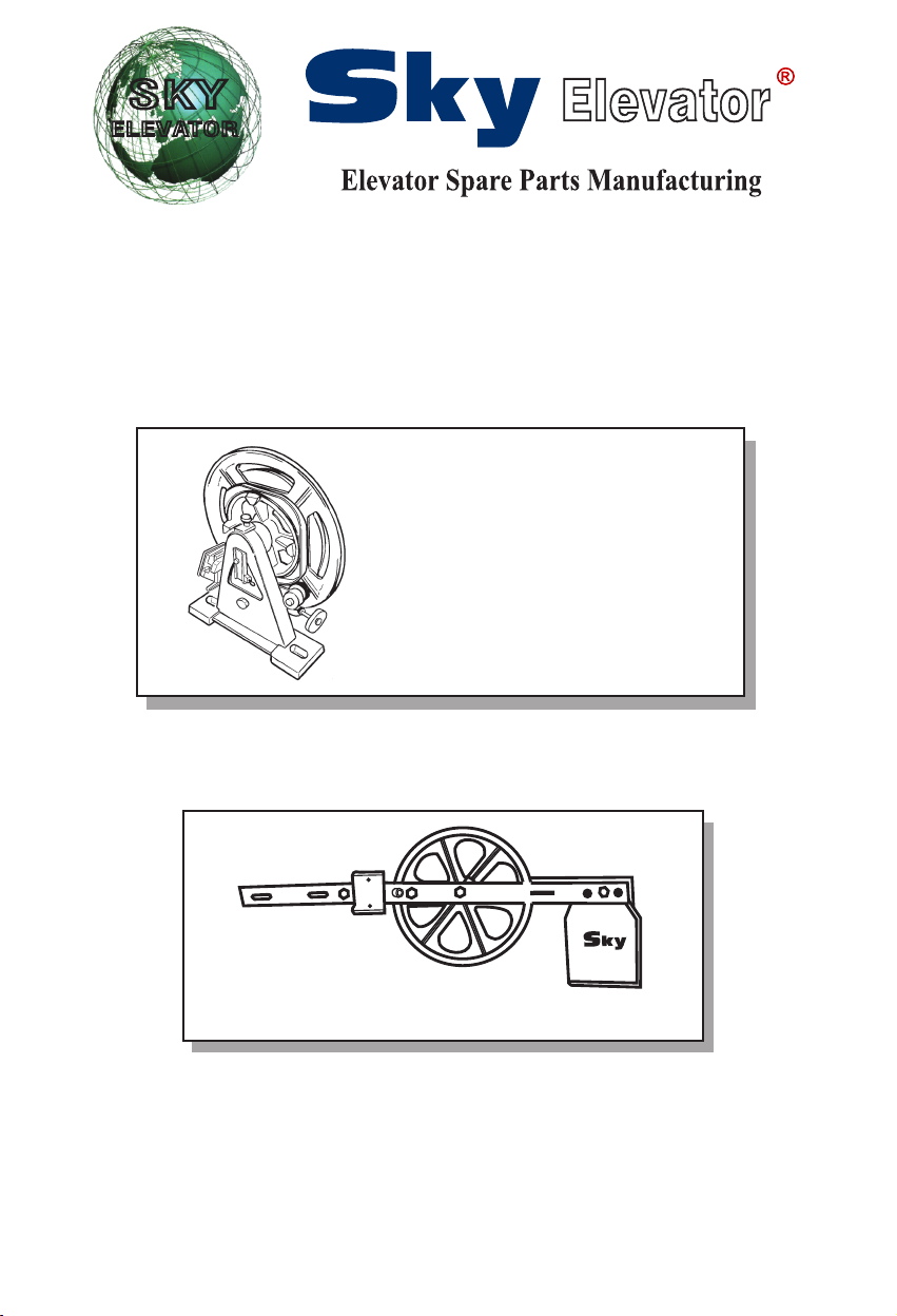
OVERSPEED GOVERNOR
MANUAL FOR SKY 200-2
SKY 200-2
1
10KG
TENSION WEIGHT WITH HORIZONTAL
COUNTERWEIGHT
TYPE SKY-281
TYPE SKY 200-2

OPERATING INSTRUCTIONS
INDEX PAGE
1 GENERAL INFORMATION BEFORE BEGINNING THE ASSEMBLY 3
1.1 Descrpton, operaton mode
1.2 Responsblty and guarantee
1.3 Safety precautons 6
1.4 Workng nstructons on safety structural elements 6
1.5 Operatons schedulng 7
1.6 Type-plate, EC-certficaton mark, dentficaton
1.7 Consttuton of supply
2 ASSEMBLY 9
2.1 Assembly of the overspeed governor 9
2.1.1 Assembly n the engne room 9
2.1.2 Assembly on the top of the elevator shaft 10
2.2 Assembly of the rope of the overspeed governor/tenson weght wth counterweght 11
2.3 Electrc nstallaton of the safety swtches 13
3 SETTING UP OPERATIONS 14
3.1 Overspeed governor 14
3.2 Tenson weght wth counterweght 14
4 OPERATION TESTING 15
5 MAINTENANCE, CONTROL, REPAIR 16
5.1 Mantenance and control 16
5.2 Executon of repars 16
6 TECHNICAL DATA 17
6.1 Overspeed governor type SKY 200-2 17
6.2 Tenson weght wth counterweght 18
* SKY 200-2 = Bdrectonal nterventon
SKY 281 = Down drecton nterventon
2
6
3
7
8
3
1 GENERAL INFORMATION BEFORE BEGINNING THE ASSEMBLY
1.1 DESCRIPTION, OPERATION MODE
The overspeed governor s a safety devce whch turns on when the allowed speed of the elevator car s excee-
ded.
If the elevator car, durng ts upward/downward run, exceeds ts nomnal permssble speed, (untl the trppng
speed s reached), the overspeed governor turns on and, n turn, releases – on the overspeed governor rope – a
brake mechansm, called safety gear, whch s located on the elevator car. The elevator car stops and s kept
back by the gudes.
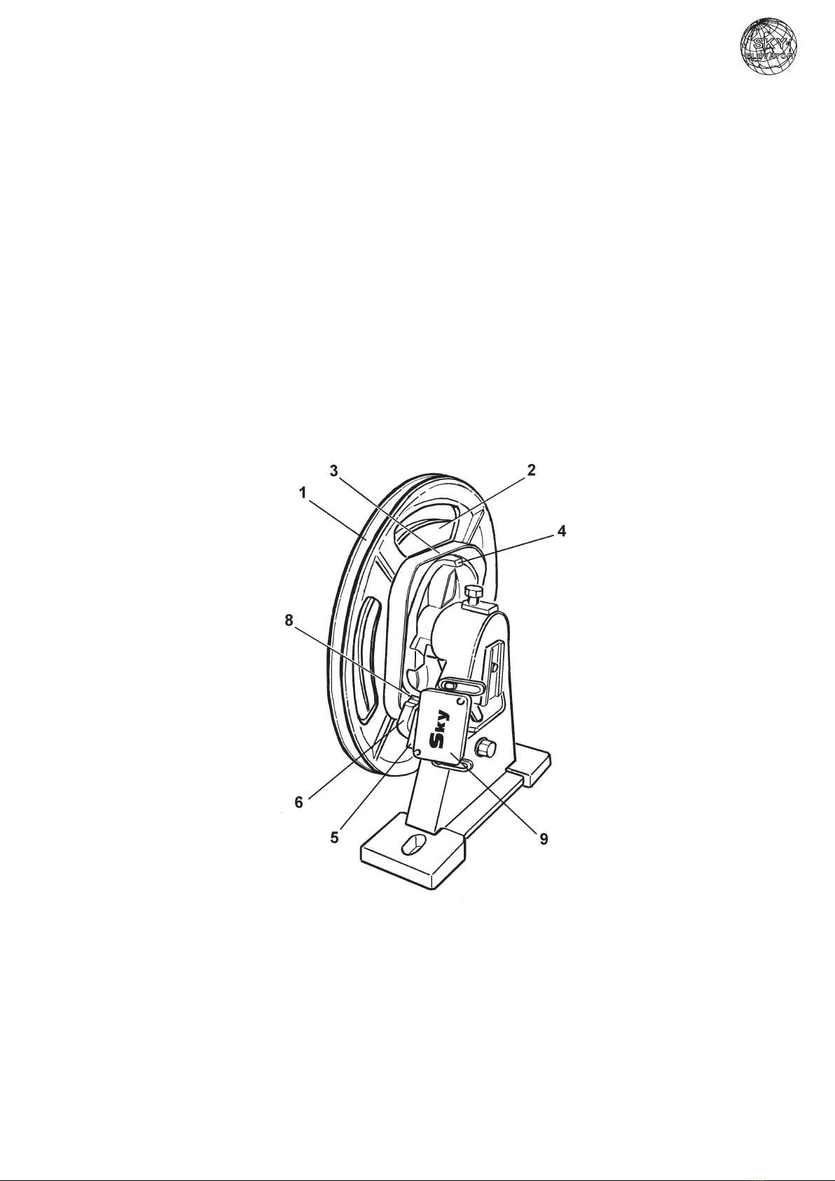
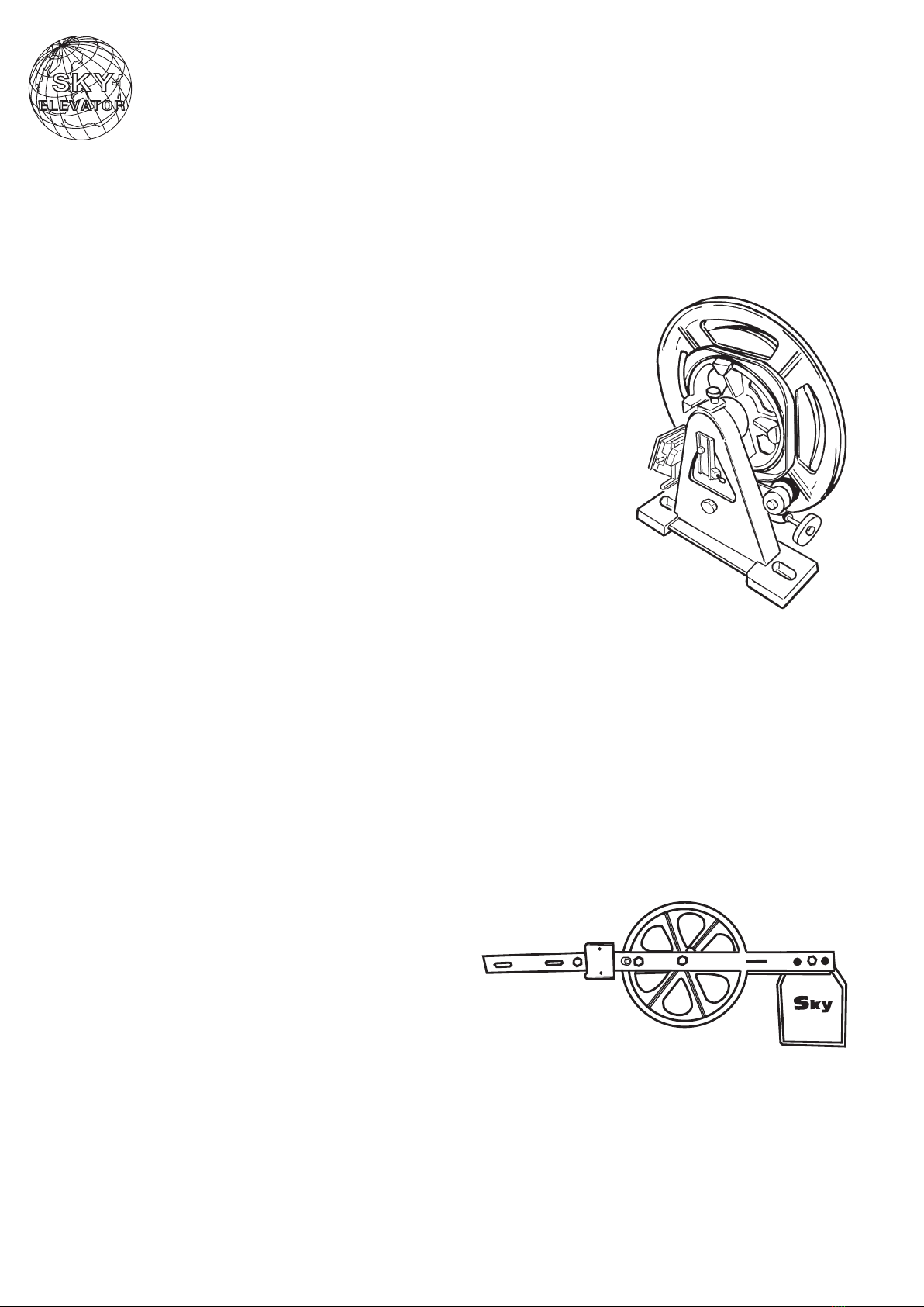
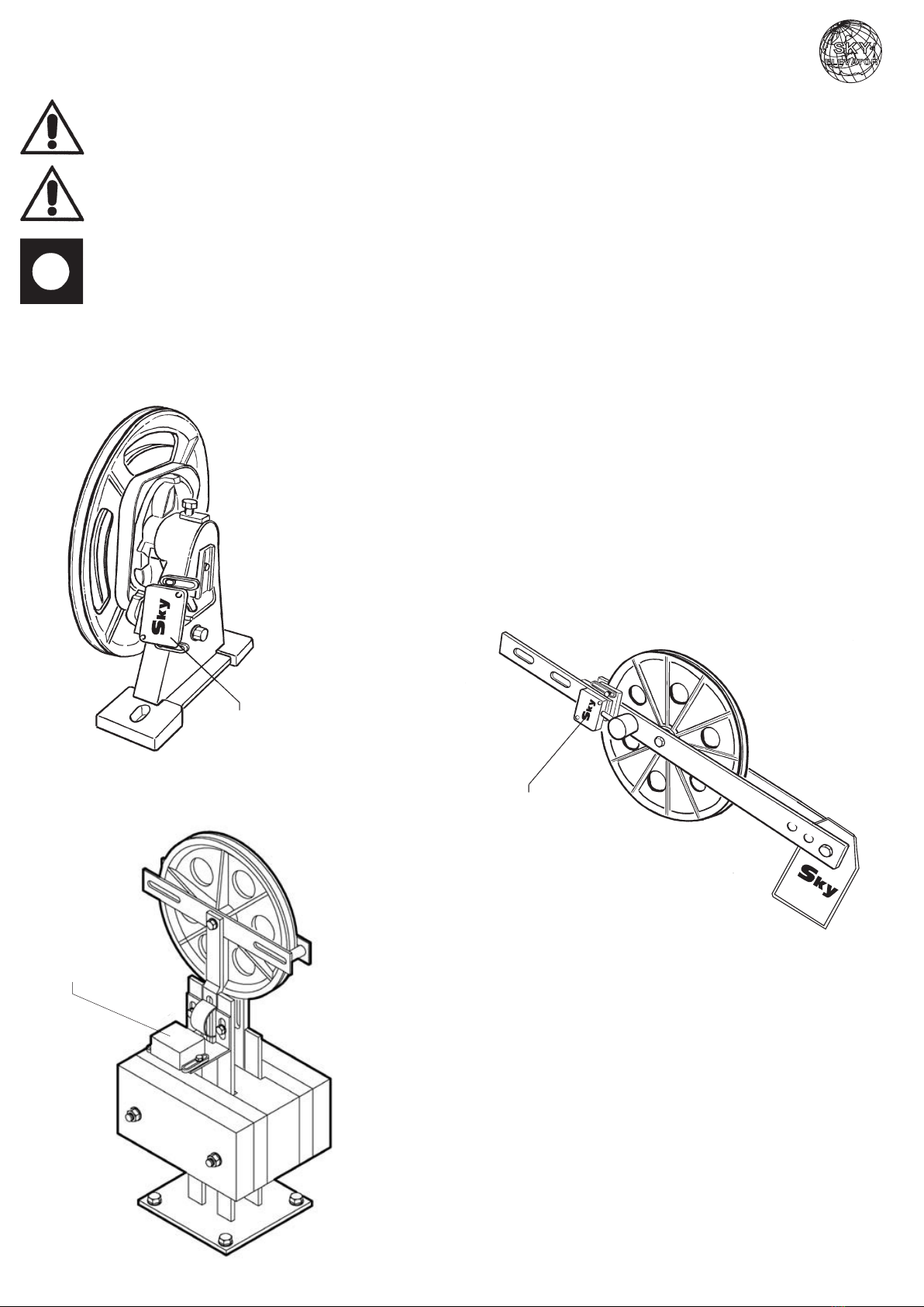
The same overspeed governor (fig. 1) s made up of pulley wth:
- governor wheel (1) wth trapezodal undercut groove to house the overspeed governor rope
- test grooves for operaton tests (2)
- cam rm (3);
- eccentrc stop (4).
The rope, secured to the clamp of the safety gear and stretched by a weght, operates the governor wheel (1)
through ts own pressure n the trapezodal undercut groove.
Besde the trapezodal groove, a cam rm (3) wth eccentrc stop (4) s also mounted on the governor wheel.
Such rm allows the pendulum (6) to operate wth an upward/downward oscllatng moton, by means of a pul-
ley mounted on a ball bearng.
The pendulum s drawn to the cam rm by a preloaded tenson sprng, correspondng to the scheduled trppng
speed.
By reachng the trppng speed, the swng of the pendulum on the cam becomes so extended, that the osclla-
tng dog clutch (8) meets the perpheral gude of the eccentrc stop, where t s clamped.
A plate (5) appled on the pendulum operates the safety swtch (9) before the mechancal clampng of the pen-
dulum. Through t, the control power of the plant s swtched off.
Fg. 1
Overspeed governor
SKY 200-2
4
The overspeed governor can be suppled for the assembly n the engne room.
DISPOSITION IN THE ENGINE ROOM
Overspeed governor
Rope anchor
Safety gears
Control devce
Governor rope

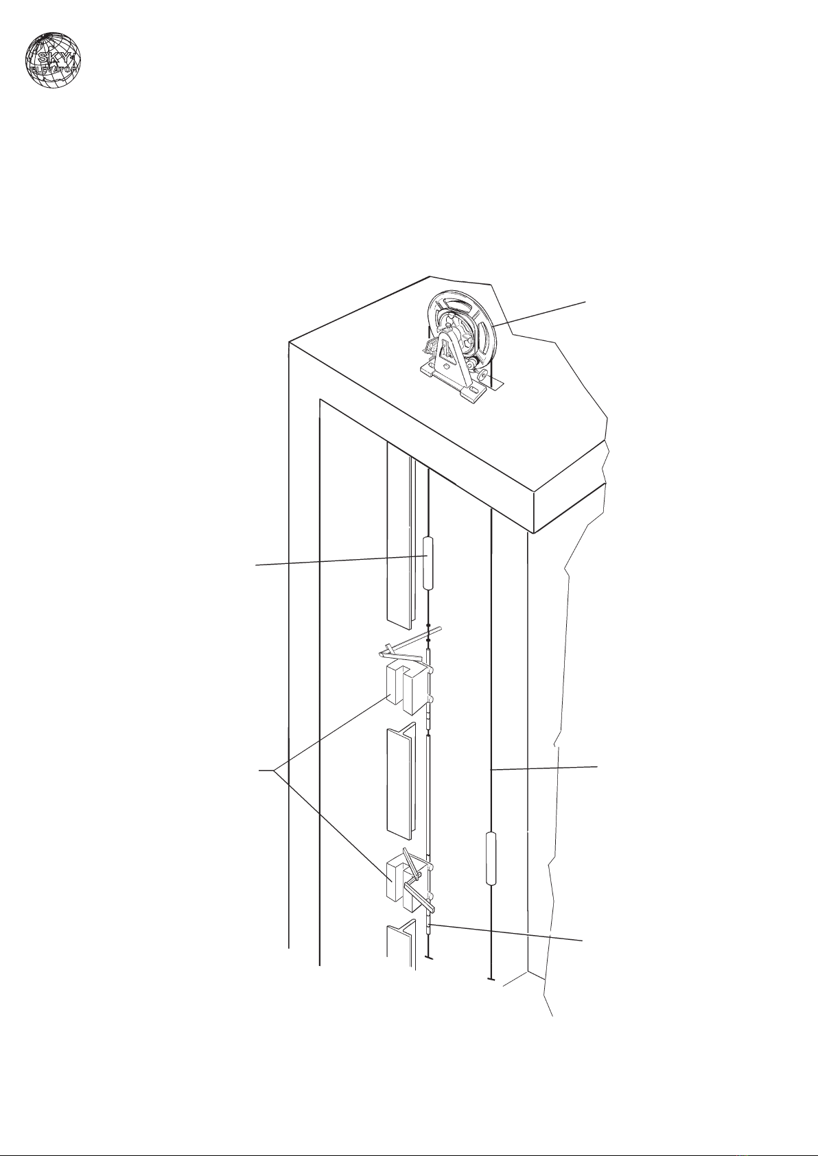
For the assembly on the top of the elevator shaft, the overspeed governor must be easly accessble
from the outsde (e.g. through a mantenance door).
DISPOSITION ON THE TOP OF THE ELEVATOR SHAFT
5
Overspeed governor
Cosse
Governor rope
Governor console
Safety gears
Control devce
Mantenance door
1.2 RESPONSIBILITY AND GUARANTEE
These operatng nstructons are addressed to persons, who are well acquanted wth the assembly of eleva-
tors. Thorough knowledge of the elevator constructon and mantenance are necessary.
The firm P.F.B. declnes any responsblty for damages, dervng from not workmanlke or smlar actons, that
have not been carred out accordng to the followng operatng nstructons and that therefore may damage the
characterstcs of the product.
P.F.B.’s guarantee may not be vald f the component part s used n a dfferent way than that descrbed n these
nstructons.
For techncal securty reasons, t s not allowed:
• assemblng of wrong overspeed governors, or governors destned to other applcatons than the ntended one
• ntroducton of changes of any knd to the overspeed governor.
1.3 SAFETY PRECAUTIONS
Generally the fitters are themselves responsble for the safety of the work.
The observance and respect of all the safety regulatons n force and the legal rules are necessary to avod da-
mages to persons and to the product durng the assembly, mantenance and repar.
Instructons that should be partcularly consdered regardng safety and damage preventon are ponted out
wth the followng symbols:
ATTENTION! Indcaton of danger. It ndcates stuatons, that nvolve rsks for the persons and stres-
ses out behavoural procedures.
DANGER! Indcaton of danger of possble damages to the structural element and to ts component
parts (e.g.: mstakes n the assembly, etc.).
IMPORTANT! Indcaton of useful nformaton.
The followng operatng nstructons are an ntegral part of the whole plant. They must be kept n a protected
and easly accessble place (such as for nstance n the engne room).
1.4 WORKING INSTRUCTIONS ON SAFETY STRUCTURAL ELEMENTS
Overspeed governors belong to the safety structural elements group. It s absolutely necessary to observe the
rules and regulatons that refer to ths structural element, ncludng the nformaton gven n the operatng n-
structons.
For that reason, before begnnng to work on ths component part, the followng operatng must be
red and understood, n partcular wth regard to the chapter concernng “safety precautons”.
Safety devces need partcular attenton. Ther perfect functonng s essental for a safe operaton of the plant.
The regulaton of the safety devces, that can be set only after the assembly, must be carred out mmedately
after the assembly tself.
If safety devces are already preset at the factory, ther operatons have to be mmedately tested.
Should t be necessary to dsassemble the safety devces durng mantenance or repar, when termnated they
have to be mmedately reassembled and adequately tested.
In these nstructons, the followng safety devces are descrbed:
• safety swtch on the overspeed governor (adjusted n the factory)
• safety swtch on the tenson weght wth counterweght (only n the plants that are n conformty wth
EN81).
6
1.5 OPERATIONS SCHEDULING
Before begnnng the assembly, t must be made clear, n one’s own nterests, whch are the constructonal con-
dtons and condtons relatng to the space avalable, n order to carry out the assembly works n a safety con-
dtons and followng a logcal order.
It s therefore advsable, consderng all the gven crcumstances, to mentally smulate the varous processes
before the assembly actvty s nconsderately or hastly undertaken.
On recept of the supply, t s necessary to check the goods, by comparng each sngle part wth the purchase
order, n order to verfy ther conformty and completeness.
The data contaned n the type-plate have to be compared wth the order.
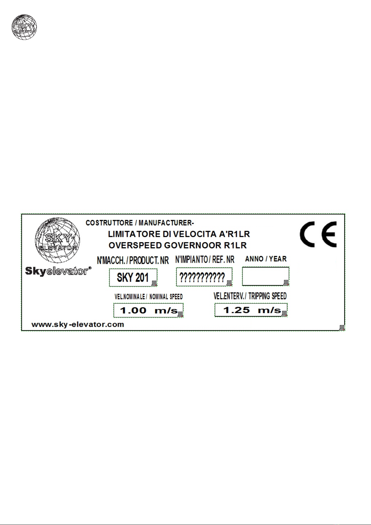
1.6 TYPE-PLATE, TEST MARK, IDENTIFICATION
The type-plate of the OVERSPEED GOVERNOR s attached to the structure on the sde.
The retaler of the plant s responsble for t beng legble.
7
2021
Sky Elevator
1.7 CONSTITUTION OF SUPPLY
Fg. 2
Tenson weght wth horzontal counterweght for the gude and
tenson of the rope (optonal wth safety swtch for the verson n
conformty to EN 81).
Fg. 1
Overspeed governor Type SKY 200-2
Abb. 1
Abb. 2
8
10KG
SKY 200-2
9
2 ASSEMBLY
For all the assembly works n the engne room or n the elevator shaft, t should be made clear that:
The entrance nto the assembly area, resp. the executon of all works can be carred out only by skl-
led workers.
In partcular, the followng safety measures should be respected:
Fx the ant-fall protecton devce (workng platform, for safety of the persons);
- cover the hole n the floor;
- secure the assembly tools and other objects to avod falls;
- n case the works have to be executed n the elevator shaft, lock the doorways and attach the ap-
proprate warnng sgn.
2.1 ASSEMBLY OF THE OVERSPEED GOVERNOR
2.1.1 ASSEMBLY IN THE ENGINE ROOM
PREPARATION
The assembly of the overspeed governor occurs ether drectly on the floor n the engne room or on a support.
Floor and support must resst to a pressure of 25 kN
In the elevators n conformty to EN 81, the passng openngs of the rope should be kept as small as
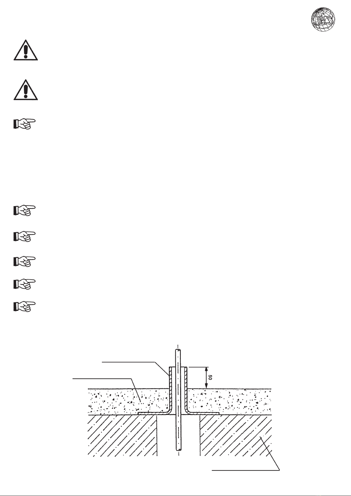
possble and must be fitted wth safety rngs 50mm hgh.
For elevators n conformty to TRA, the same procedure s recommended.
Before the assembly takes place, t s necessary to fix an adequate safety rng on the floor.
If, after the assembly on the cement, a stone floor s lad down, ts heght should be consdered (fig. 1)
Safety rng
Stone floor
Shaft coverng
Fg. 1
27
ASSEMBLY STEPS
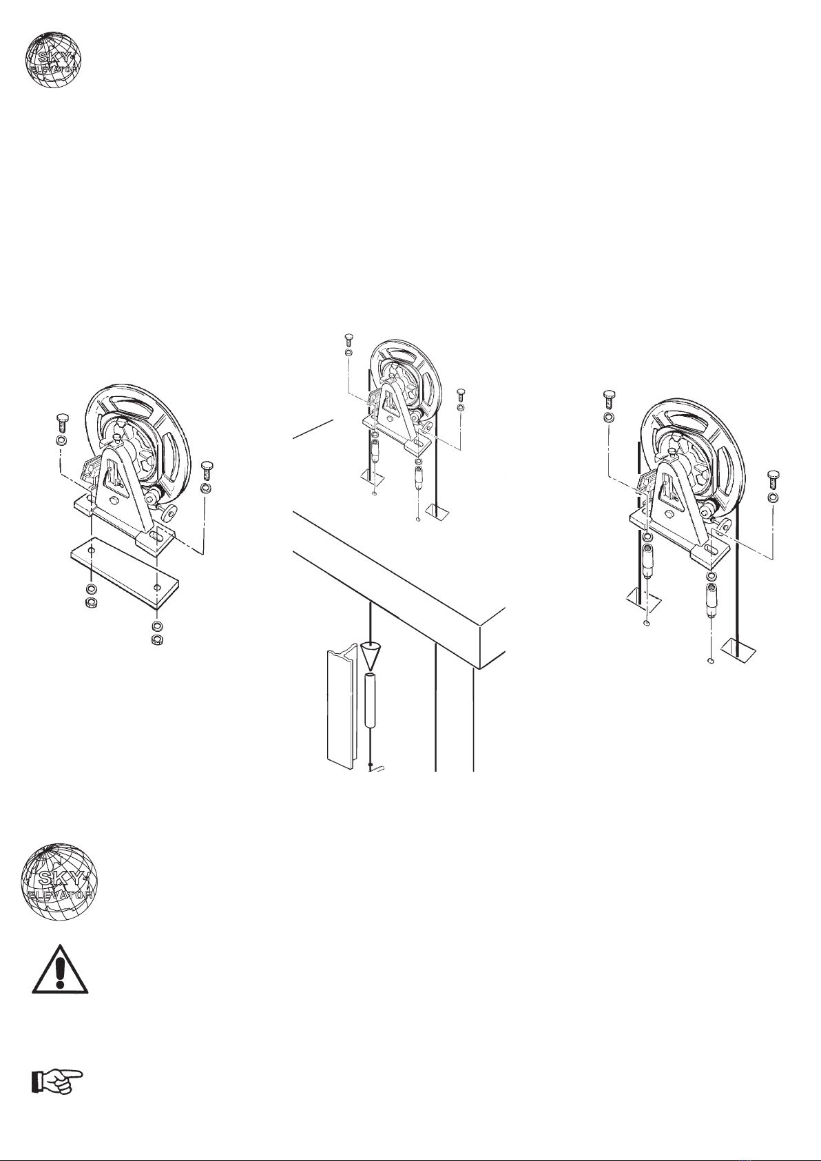
• If a support s used, first of all screw t on together wth the over-
speed governor (fig. 1).
• Place the overspeed governor on the passng openng of the ro-
pe and algn t wth the plumb lne to the brake devce, .e. the sa-
fety gear (fig. 2).
• Mark the drlled holes and place the nserts (the nserts must re-
sst to the operaton load of at least 2 kN).
• Fx the overspeed governor (fig. 3).
Fg. 1
Abb. 1
Fg. 2
Abb. 2
Fg. 3
Abb. 3
2.1.2 ASSEMBLY ON THE TOP OF THE ELEVATOR SHAFT
Safety measures, referrng to works on elevator plants, must be observed.
Mount the overspeed governor as shown n fig. 1 and 2 (or n an opposte way).
In case of assembly n the elevator shaft, the overspeed governor must be easly accessble from the
outsde (e.g. through an nspecton door for mantenance operatons).
10

2.2 ASSEMBLY OF THE ROPE OF THE OVERSPEED GOVERNOR/TENSION WEIGHT
WITH HORIZONTAL AND VERTICAL COUNTERWEIGHT
A techncally perfect operaton of the overspeed governor s only possble wth a correct assembly of the go-
vernor rope tself and of the tenson weght wth counterweght.
Whle determnng at whch heght the tenson weght wth counterweght has to be mounted, t must be made
clear that:
- n no case, the counterweght must touch the floor (fig. 1 and 2), otherwse, the functon of the overspeed
governor s put out of operaton;
- when the framework of the elevator car reaches ts lowest poston (by the compressed buffer), the lower
rope-anchor and the downward remanng rope-end must not meet the pulley of the tenson weght.
• Cut the overspeed governor rope sufficently and lay t down on the rope pulley of the tenson weght.
• Supply the first rope-end wth the rope-anchor (fig. 1 and 2) and attach t to the safety gear.
• Let the second pece of rope drop nsde the elevator shaft.
Safety
gears
Mountng
support
Counterweght
Tenson
weght pulley
Rope
anchor
Governor
rope
Fg. 1
Fg. 2
Safety gears
Counterweght
Tenson
weght
pulley
Rope
anchor
Governor
rope
11
10KG

TENSION PULLEY WITH HORIZONTAL COUNTERWEIGHT
• Mount the mountng support at about 450 mm (ap-
prox. value, fig. 3) on the bottom of the shaft.
• Hold the counterweght, untl t s n an oblque pos-
ton (fig. 3).
• In the presence of a brake mechansm actng up-
wards, mount the second rope-end to the rope-an-
chor of the brake devce
or:
• Supply the second rope-end wth the rope-anchor
and attach t to the safety gear.
• Remove the support n order to stretch the rope.
If the assembly has been properly carred
out, the counterweght should take a slghty
upward angled poston (fig. 3).
TENSION PULLEY WITH VERTICAL COUNTERWEIGHT
• Mount the leadng plate of the
counterweght to acheve per-
fect algnment between the
pulley of the overspeed gover-
nor and the pulley of the ten-
son weght (fig. 4).
• Hold the counterweght, untl t
reaches a heght of about 120
mm from the bottom of the
shaft (approx.value) (fig. 4).
Fg. 3
Fg. 4
10KG
12
2.3 ELECTRIC INSTALLATION OF THE SAFETY SWITCHES
All the works concernng the electrcal equpment should only be carred out by specalzed electr-
cans, sklled workers.
Before begnnng operatons, turn off the power of all the parts of the plant.
When layng the connecton cables, take care that:
• unpolar cables have a double coatng
• the use and layng of the cables are carred out accordng to the EMV rules and regulatons.
The safety swtches dsconnect the safety crcut of the elevator plant.
The followng safety swtches must be connected:
Fg. 1
Overspeed governor type SKY 200-2 - SKY 281
Fg. 2
Tenson weght wth horzontal coun-
terweght complete wth safety
swtch (only n the plants n confor-
mty to EN 81).
Fg. 3
Tenson weght wth vertcal counterweght com-
plete wth safety swtch (only n the plants n con-
formty to EN 81).
Safety swtch
Safety swtch
Safety swtch
SKY 200-2
10KG
13

3 SETTING UP OPERATIONS
3.1 OVERSPEED GOVERNOR
The safety swtch of the overspeed governor has already been set n the factory. Its poston s fixed wth sea-
lng-wax and t cannot be modfied.
The settng up of the safety swtch on the overspeed governor s not necessary.
3.2 TENSION WEIGHT WITH COUNTERWEIGHT (EN 81 and TRA)
Only n plants n conformty to EN 81:
a) wth tenson pulley wth horzontal counterweght:
• shft the mountng clamp of the tenson weght wth counterweght n such a way that the safety swtch does
not become operatve (fig. 1, pos. 1).
At the same tme take nto consderaton the stretchng of the rope!
• On the safety swtch, adjust the horzontal connectng poston on the slots (fig. 1, pos. 2).
• After the assembly, release the tenson rope and check the control functon by movng the tenson arm. Then
fix the poston wth sealng-wax or smlar.
• After the nserton, the trppng pn of the safety swtch must be reset by hand n the startng poston.
b) wth tenson pulley wth vertcal counterweght:
• Move the mountng plate of the safety swtch n the vertcal drecton (fig. 2 – pos. 1) n such a way that the
swtch does not actvate.
• On the swtch, adjust the horzontal connectng poston on the slots (fig.2 – Pos. 2).
• After the assembly, release the overspeed governor rope and check the control functon by movng the coun-
terweght slowly downwards on the gude ral and payng close attenton. Then fix the poston wth sealng
wax or smlar.
• Followng the nserton, the trppng pn of the safety swtch must be reset n the startng poston.
Fg. 1 Fg. 2
1
2
10KG
14

4 OPERATION TESTING
Although qualty and operaton of each component are controlled by the factory at the delvery, before sale,
eventually, before the final test of the plant, an operaton testng should be carred out.
TEST RUN AFTER THE ASSEMBLY
Clean the gudes before the first test run takes place.
Before the begnnng of the run, leave the elevator shaft free from persons and objects.
Before the general test takes place, t s necessary to slowly run through the whole area of acton (wth nspec-
ton control devce). After that, verfy the dstance to be sufficent for all fastenng parts (partcularly n the fixng
area of the gudes and of the governor rope).
If possble before that, locate and remove screw projectons and other dangerous narrow ponts.
Subsequently, a statc functon test has to be carred out:
• operate by hand the overspeed governor: press down the rocker lever;
• drve the elevator cars lowly downwards.
The overspeed governor must release the safety gear.
The safety swtch must release and swtch off the safety crcut of the elevator plant.
Wth a slow movement upwards and/or downwards, place the overspeed governor and the satety gear back-
wards.
CONTROL OF ALL OPERATIONS
Subsequently, the release s to be controlled at a nomnal speed, as well as the relatve safety devces.
The control of the release s to be carred out as a dynamc functon test, wth or wthout rated load of the ele-
vator car.
Durng test runs, no-one must stay n the elevator car.
Lay down the governor rope nto the test groove and drve the elevator car at nomnal speed downwards/up-
wards.
Alternatvely, the overspeed governor can be operated also by hand, by pressng the rocker lever down.
The safety swtch must release and swtch off the safety crcut of the elevator plant.
Wth a slow movement downwards/upwards, brng the overspeed governor and the brake devce (the safety
gear) back agan.
CONTROL OF THE SAFETY DEVICE FOR ROPE TENSION
The safety swtch on the tenson weght wlh counterweght s controlled by removng the rope of the overspeed
governor from the rope pulley.
When the control s finshed, the release pn of the safety swtch must be reset by hand.
15

5 MAINTENANCE, CONTROL AND REPAIR
5.1 MAINTENANCE AND CONTROL
Generally, the overspeed governor and respectve tenson weght wth counterweght do not need any mante-
nance.
The whole plant has been conceved n such a way that, wth proper use wthout damages, there s no need for
mportant mantenance nterventons.
Accordng to the frequency of use, controls of the plant should be carred out perodcally.
After substantal changes or after an accdent, t s necessary to carry out a control of the plant (see
EN 81-2, annex E2).
Ths s necessary especally when safety devces are changed.
Changes, damages or other rregulartes must be notfied and, f necessary, repared wthn the lmts of the al-
lowed feasblty.
Perodcal controls ncrease, not only the safety, but also the trouble-free and long-lfe operaton of
the plant!
Partcularly recommended are controls and mantenance operatons before the operatng tests foreseen by the
law take place.
Please contact your suppler f there are any doubts regardng the operaton efficency of the components of
the plant.
MAINTENANCE AND CONTROL SCHEDULE
• Check every 6 (sx) months the operaton efficency of the overspeed governor.
• Check the damage or the dstortons of the overspeed governor and respectve structural elements.
• Check the wear of the undercut grooves of the overspeed governor and the grooves of the tenson pulley.
Danger of tear to the rope! When the governor rope runs n an rregular way, that s to say when the
outlne of the rope remans stamped n the groove of the overspeed governor.
• Control that the rocker lever s easly movable. If necessary, replace t.
• Control the safety swtch by hand (manual release).
• Keep the plant clean from drt and partcularly the sgns and the type-plates must always be kept legble.
5.2 EXECUTION OF REPAIRS
Generally, also n case of repars, the overspeed governor cannot be dsassembled or modfied n any other
way (sealng, sealng-wax).
It s not allowed the spontaneous replacement of parts or element groups due to defects or severe
wear.
The reasons are the followng:
• rules and regulatons concernng guarantee and safety techncal dspostons;
• only orgnal spare-parts must be mounted.
It s no allowed to operate the elevator plant, even f temporarly, wthout the overspeed governor.
16

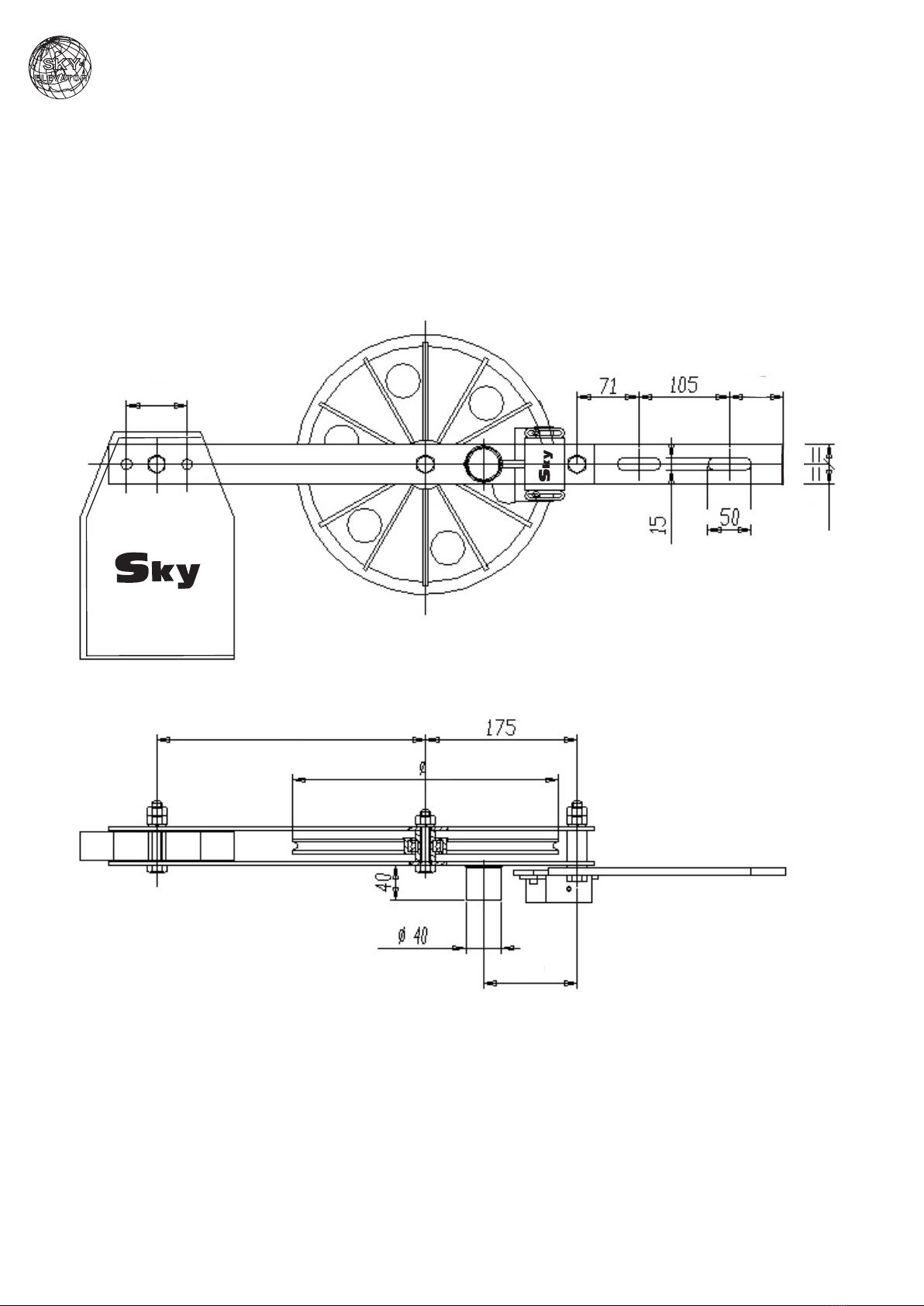
6 TECHNICAL DATA
6.1 OVERSPEED GOVERNOR TYPE SKY 200-2 - SKY 281
Ingrandmento “A”
“A” nset
Agrandssement “A”
Vergrösserung “A”
Amplacon “A”
N.2 asole 16
No. 2 slots 16
N° 2 ajours 16
Nr. langlòcher 16
2 ranuras 16
TENSION OPERATION OF THE GOVERNOR ROPE
After startng and runnng the plant for a longer tme, t mght be necessary to slghtly stretch the governor rope
agan.
Pay attenton to the mnmum dstance between the shaft bottom and the counterweght (s. PAR. 2.2).
17
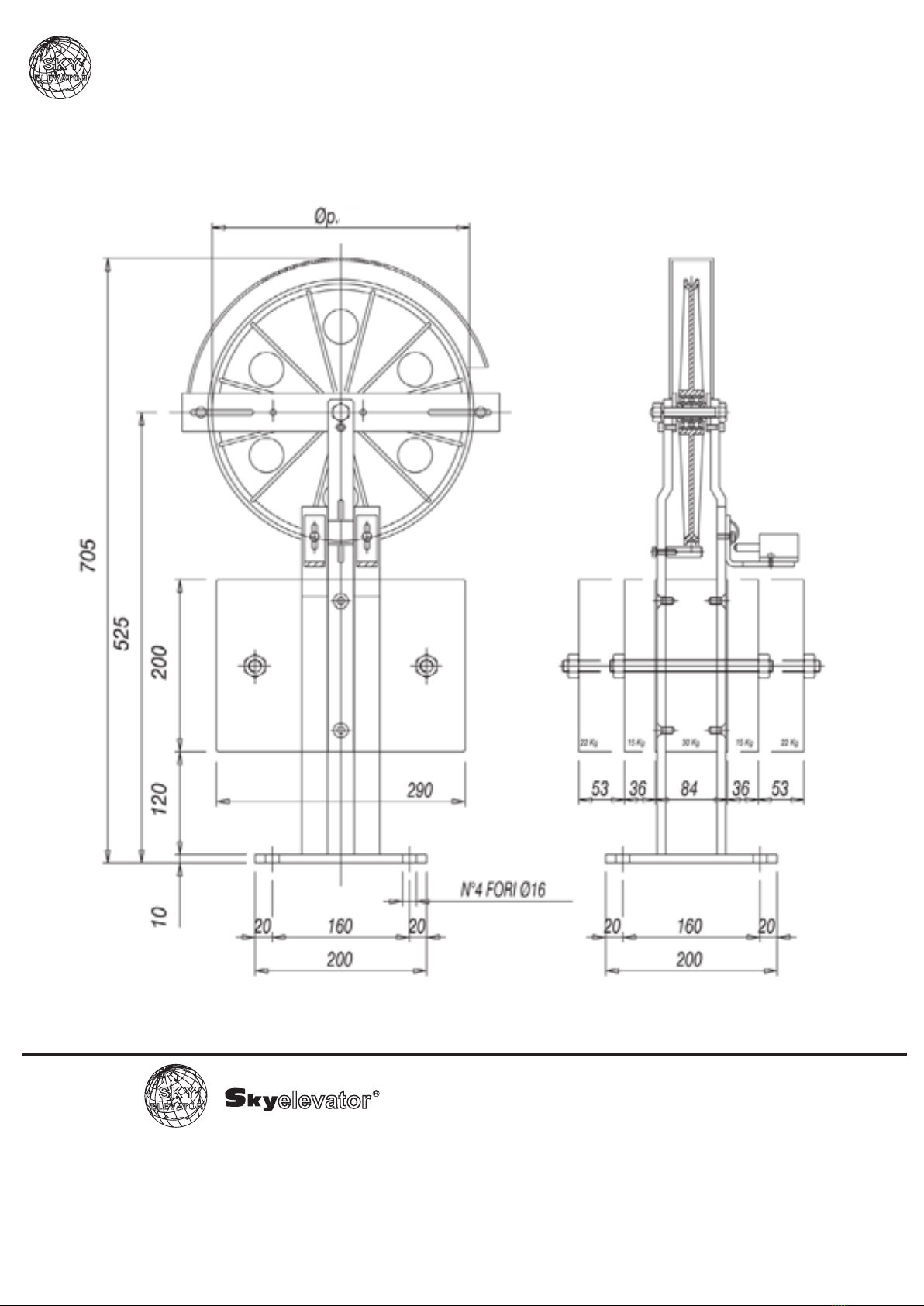
6.2 TENSION WEIGHT WITH HORIZONTAL/VERTICAL COUNTERWEIGHT
10KG
50
70
290
280
120
120
18
Component meccanc per ascensor - Mechancal lft components
SKY ELEVATOR
http://www.sky-elevator.t -
6.2 TENSION WEIGHT WITH HORIZONTAL/VERTICAL COUNTERWEIGHT
280
19
E-mal: sky@sky-elevator.com
http://www.sky-elevator.com -
E-mal: sky@sky-elevator.t
http://www.skyelevator.de - E-mal: sky@skyelevator.de
E-mal: sky@sky-elevator.bg
http://www.sky-elevator.bg -

Manufacured Date:
Serial Number :
2021
Table of contents
Popular Lifting System manuals by other brands


Vestil
Vestil PAL-D owner's manual

Atlas
Atlas PV-15PX Installation & operation manual

Herkules Hebetechnik GmbH
Herkules Hebetechnik GmbH K1200-HLS-R Operating manual and test record

logitrans
logitrans LOGIFLEX SELFR manual

Mohawk
Mohawk IA user manual

Challenger Lifts
Challenger Lifts THK installation manual

Beissbarth
Beissbarth VLH 4440 Original instructions

morse
morse 400A-72SS-117 Operator's manual

Braun
Braun NL955 Series Operator's manual

R. Beck Maschinenbau
R. Beck Maschinenbau HS 600 operating manual

Oshkosh Corporation
Oshkosh Corporation JLG AE1932 Service maintenance manual

Audipack
Audipack PCL-M350 manual