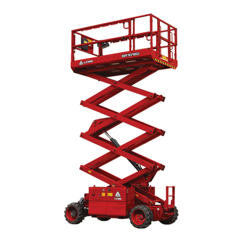
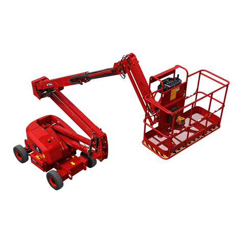
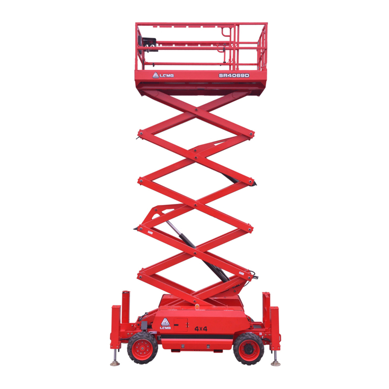
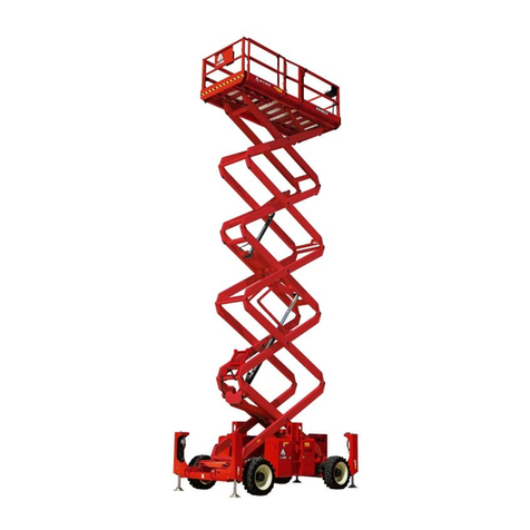
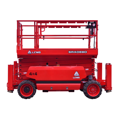
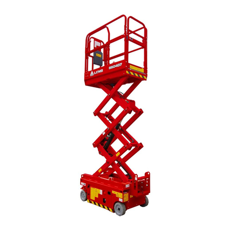
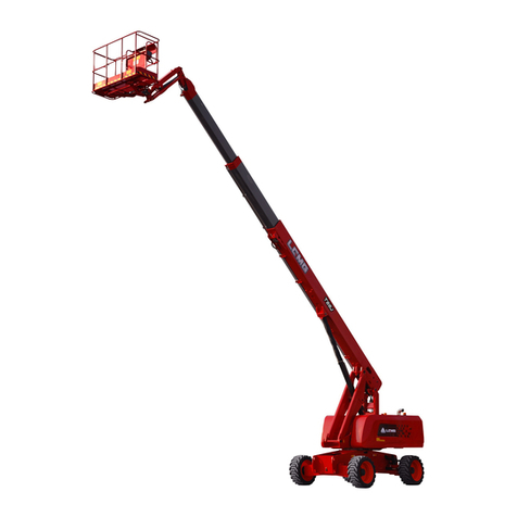
LGMG S1932 II User manual

Service Manual
S1932 II/S1932E II/S2632 II/S2632E II
S2646 II/S2646E II /S3246 II/S3246E II
S4046 II/S4046E II/ S4650 II/S4650E II
Scissors Mobile Elevating Work Platform
△
!WARNING
Before operation and maintenance, the
drivers and maintenance personnel are
required to read this manual thoroughly.
Otherwise, fatal accident may occur. This
manual shall be kept properly for future
reference by the personnel concerned.
LINGONG HEAVY MACHINERY CO., LTD.

Scissors Mobile Elevating Work Platform
Service manual
880*1230 mm Sextodecimo 8 sheets
First edition, April 2022 First print, April 2022
L I N G O N G H E AV Y M A C H I N E R Y C O . , LT D .
Add.: 12F, Building 3, Lushang Olympic City, No. 9777, Jingshi Road, Lixia District, Jinan
City, Shandong Province, China
Tel: 86-0531-67605017 Technical service: 86-4009666569
Web: www.LGMG.com.cn Sales of accessories: 86-0531-67605016

Service Manual of Scissors Mobile Elevating Work Platform
I
Contents
Foreword ........................................................................................................................................................ VIII
Safety Notices................................................................................................................................................... IX
Chapter 1 Safety and Environment ................................................................................................................... 1
1.1 Terms and Definitions.............................................................................................................................. 3
1.2 Compliance.............................................................................................................................................. 3
1.3 Before maintenance ................................................................................................................................ 3
1.4 Workplace requirements......................................................................................................................... 3
1.5 Safety precautions for maintenance and repair...................................................................................... 3
1.6 Intended use............................................................................................................................................ 4
1.7 Description............................................................................................................................................... 4
Chapter 2 Product Introduction ........................................................................................................................ 7
2.1 Machine parameters ............................................................................................................................... 9
2.1.1 S1932 II(S193202WDQ0AH1000)machine parameters ............................................................ 9
2.1.2 S1932EⅡ(S193202WDQ0AE1000)machine parameters ............................................................... 10
2.1.3 S2632Ⅱ(S263202WDQ0AH1000)machine parameters................................................................. 11
2.1.4 S2632EⅡ(S263202WDQ0AE1000)machine parameters ............................................................... 12
2.1.5 S2646Ⅱ(S264602WDQ0AH1000)machine parameters................................................................. 14
2.1.6 S2646EⅡ(S264602WDQ0AE1000)machine parameters ............................................................... 15
2.1.7 S3246Ⅱ(S324602WDQ0AH1000)machine parameters................................................................. 16
2.1.8 S3246EⅡ(S324602WDQ0AE1000)machine parameters ............................................................... 17
2.1.9 S4046Ⅱ(S404602WDQ0AH1000)machine parameters................................................................. 19
2.1.10 S4046EⅡ(S404602WDQ0AE1000)machine parameters ............................................................. 20
2.1.11 S4650Ⅱ(S465002WDQ0AH1000)machine parameters............................................................... 21
2.1.12 S4650EⅡ(S465002WDQ0AE1000)machine parameters ............................................................. 22
2.2 Specification for selection of tightening torque of the lifting platform................................................ 23
2.3 Key component moment table.............................................................................................................. 26
Chapter 3 Platform .......................................................................................................................................... 27
3.1 Removal and installation of PCU ........................................................................................................... 29
3.1.1 Removal of PCU .............................................................................................................................. 29
3.1.2 Installation of PCU .......................................................................................................................... 29
3.2 Removal and installation of platform assembly.................................................................................... 29
3.2.1 Removal of platform assembly (S1932Ⅱ, S1932EⅡ).................................................................... 29
3.2.2 Installation of platform assembly (S1932 II, S1932 E II)................................................................. 30
3.2.3 Removal of platform assembly (S2632Ⅱ, S2632EⅡ, S46Ⅱ, S46EⅡ, S4650Ⅱ, S4650EⅡ)......... 32

Service Manual of Scissors Mobile Elevating Work Platform
II
3.2.4 Installation of platform assembly (S2632 II, S2632 E II, S46 II, S46 E II, S4650 II, S4650 E II)......... 33
3.2.5 Folding of platform guardrail.......................................................................................................... 34
3.3 Removal and installation of pedal......................................................................................................... 39
3.3.1 Removal of pedal............................................................................................................................ 39
3.3.2 Installation of pedal........................................................................................................................ 39
3.4 Removal and installation of wheel frame and wheels ........................................................................ 40
3.4.1 Removal of wheel frames and wheels............................................................................................ 40
3.4.2 Installation of wheel frames and wheels........................................................................................ 40
3.5 Removal and installation of semi-swing gate........................................................................................ 42
3.5.1 Removal of semi-swing gate........................................................................................................... 42
3.5.2 Installation of the semi-swing gate ................................................................................................ 42
Chapter 4 Fork................................................................................................................................................. 45
4.1 Removal of fourth fork (S1932 II, S1932E II, S2632 II, S2632E II, S2646 II, S2646E II)........................... 47
4.2 Fourth layer fork assembly (S1932II, S1932EII, S2632II, S2632EII, S2646II, S2646EII).......................... 53
4.3 Removal of fifth layer fork (S3246 II, S3246 II)...................................................................................... 64
4.4 Installation of fifth layer fork (S3246Ⅱ, S3246EⅡ).............................................................................. 71
4.5 Removal of six-layer fork (S4046 Ⅱ, S4046EⅡ, S4650Ⅱ, S4650EⅡ)................................................. 88
4.6 Installation of sixth layer fork (S4046Ⅱ, S4046 EⅡ, S4650Ⅱ, S4650 EⅡ).......................................... 92
4.7 Fork slider replacement....................................................................................................................... 106
Chapter 5 Chassis........................................................................................................................................... 107
5.1 Battery Side Assembly......................................................................................................................... 109
5.1.1 Left Lock Assembly ....................................................................................................................... 109
5.1.2 Assembly of S1932EⅡhorn and buzzer ..................................................................................... 109
5.1.3 Assembly of S2632 Ⅱ, S2632E Ⅱ, S46 Ⅱ, S46E Ⅱhorns and buzzers................................. 109
5.1.4 Assembly of S4650Ⅱand S4650EⅡhorns and buzzers ........................................................... 110
5.1.5 Assembly of fuse holder and DC power switch............................................................................ 110
5.1.7 S1932Ⅱ, S1932EⅡbattery assembly.......................................................................................... 110
5.1.8 Assembly of S2632Ⅱ, S2632EⅡ, S46Ⅱ, S46EⅡ, S4650Ⅱand S4650EⅡbatteries ............... 111
5.2 Fuel tank side assembly....................................................................................................................... 111
5.2.1 Motor and pump assembly .......................................................................................................... 111
5.2.2 Assembly of power unit................................................................................................................ 112
5.2.3 Assembly of electrical control unit............................................................................................... 112
5.2.4 Filter assembly.............................................................................................................................. 113
5.2.5 Platform control panel assembly.................................................................................................. 113
5.2.6 Assembly of MCU ......................................................................................................................... 113
5.3 Chassis Components............................................................................................................................ 114
5.3.1 Assembly of Work Indicator Lamp................................................................................................ 114

Service Manual of Scissors Mobile Elevating Work Platform
III
5.3.2 Assembly of inclination switch ..................................................................................................... 114
5.3.3 Assembly of Upper and Lower Limit Switches ............................................................................. 114
5.3.4 Assembly of pit travel switch........................................................................................................ 115
5.3.5 Assembly of Shaft Fixing Module ................................................................................................. 115
5.3.6 Assembling of gas spring, connecting rod and welded connecting rod assembly....................... 115
5.3.7 Wheel Assembly (S1932 II, S1932E II) .......................................................................................... 116
5.3.8 Wheel assembly (S2632 II, S2632E II, S46 II, S46E II, S4650 II, S4650E II) .................................... 116
Chapter 6 Hydraulics ..................................................................................................................................... 119
6.1 Hydraulic schematic diagram .............................................................................................................. 121
6.1.1 Hydraulic schematic diagram of S1932II ...................................................................................... 121
6.1.2 Hydraulic schematic diagram of S1932EⅡ.................................................................................. 122
6.1.3 Hydraulic schematic diagram of S2632Ⅱ.................................................................................... 123
6.1.4 Hydraulic schematic diagram of S2632EⅡ.................................................................................. 124
6.1.5 Hydraulic schematic diagram of S2646Ⅱ.................................................................................... 125
6.1.6 Hydraulic schematic diagram of S2646EⅡ.................................................................................. 126
6.1.7 Hydraulic schematic diagram of S3246 and S4046Ⅱ................................................................... 127
6.1.8 Hydraulic schematic diagram of S3246EⅡ, S4046EⅡand S4650EⅡ........................................ 128
6.1.9 Hydraulic schematic diagram of S4650Ⅱ.................................................................................... 129
6.2 Valve .................................................................................................................................................... 130
6.2.1 Installing the spool ....................................................................................................................... 130
6.2.2 Power unit FC-420-1 (S1932E Ⅱ)................................................................................................ 130
6.2.3 Scissor lift platform control valve ST5188-AE0A (S1932II, S2632II) ............................................. 131
6.2.4 Scissor lift platform control valve ST6158-AE00 (S2632 EⅡ, S46EⅡ, S4650EⅡ)....................... 132
6.2.5 Scissor lift platform control valve ST6887-AE00 (S2646 Ⅱ, S46 Ⅱ, S4650 Ⅱ)........................ 133
6.2.6 Lower cylinder valve block assembly ST5006-AC00 (S1932 II, S1932E II, S2632 II, S2632E II)..... 135
6.2.7 Lower lift cylinder valve block assembly ST4846-AC0A (S46II, S46EII, S4650II, S4650EII)........... 136
6.2.8 Upper cylinder valve block assembly ST4960-AC0B (S4046EⅡ, S4046EⅡ)................................ 137
6.2.9 upper cylinder valve block assembly ST4960-AC00 (S4650 Ⅱ, S4650 EⅡ)................................ 138
6.2.10 Testing solenoid valve coil.......................................................................................................... 138
6.3 Lift cylinder disassembly and assembly............................................................................................... 139
6.3.1 Lift cylinder removal..................................................................................................................... 139
6.3.2 Assembly of lift cylinder ............................................................................................................... 141
6.4 Traveling hydraulic assembly............................................................................................................... 142
6.4.1 Removal of steering cylinder........................................................................................................ 142
6.4.2 Removal of Steering Knuckle........................................................................................................ 143
6.4.3 Disassembly and assembly of walking motor/drive motor.......................................................... 143
6.4.4 Disassembly and Assembly of Gear Pump.................................................................................... 145

Service Manual of Scissors Mobile Elevating Work Platform
IV
6.4.5 6.4.5 Removal and installation of hydraulic tank......................................................................... 146
6.5 Service brake assembly ....................................................................................................................... 148
6.5.1 r Removal of brake disc (hydraulic drive)..................................................................................... 148
6.5.2 Assembly of brake discs (hydraulic drive) .................................................................................... 149
6.5.3 Assembly of Brake Release Valve (hydraulic drive)...................................................................... 150
Chapter 7 Electrics......................................................................................................................................... 151
7.1 Precautions for work of electrical system........................................................................................... 153
7.2 Schematic Diagram of Location of Main Electrical Appliances ........................................................... 153
7.3 Electrical schematic diagram............................................................................................................... 155
7.3.1 Electrical schematic diagram (electric drive)................................................................................ 155
7.3.2 Electrical schematic diagram (hydraulic drive)............................................................................. 156
7.4 Main electrical components................................................................................................................ 157
7.4.1 Platform control unit (PCU).......................................................................................................... 157
7.4.2 Platform control unit (PCU).......................................................................................................... 157
7.4.3 Electrical control unit (ECU).......................................................................................................... 158
7.4.4 Electronic control unit (ECU) ........................................................................................................ 158
7.4.5 Battery.......................................................................................................................................... 160
7.5 Harness................................................................................................................................................ 163
7.5.1 Table of S1932E Ⅱmain harness wiring diagram and wire number......................................... 163
7.5.2 S2632EⅡ, S46Ell Main harness wiring diagram and wire size table............................................ 165
7.5.3 S4650EⅡMain harness wiring diagram and wire size table ...................................................... 167
7.5.4 S1932ⅡMain harness wiring diagram and wire size table ........................................................ 169
7.5.5 S2632Ⅱ, S46ⅡMain harness wiring diagram and wire size table ............................................ 171
7.5.6 S4650 ⅡMain harness wiring diagram and wire size table ...................................................... 173
7.5.7 S1932 II and S1932E II PCU harness and fork harness.................................................................. 175
7.5.8 S2632 Ⅱ, S2632E ⅡPCU harness and fork harness ................................................................ 176
7.5.9 S2646Ⅱ, S2646 EⅡPCU harness and fork harness ................................................................... 177
7.5.10 S3246Ⅱ, S3246EⅡPCU harness and fork harness .................................................................. 178
7.5.11S4046Ⅱand S4046EⅡPCU harness and fork harness ............................................................. 179
7.5.12S4650Ⅱand S4650EⅡPCU harness and fork harness ............................................................. 180
7.5.13 Troubleshooting of Electrical Wiring.......................................................................................... 181
7.6 Error code (alarm code)....................................................................................................................... 182
7.6.1 Alarm code table .......................................................................................................................... 182
7.6.2 Operation flow diagram ............................................................................................................... 186
Chapter 8 Maintenance of Complete Machine............................................................................................. 187
8.1 Checking the battery ........................................................................................................................... 189
8.2 Check the hydraulic oil ........................................................................................................................ 189

Service Manual of Scissors Mobile Elevating Work Platform
V
8.3 check the wire ..................................................................................................................................... 191
8.4 check tire and hub............................................................................................................................... 191
8.5 Checking ventilation system of the hydraulic tank cover.................................................................... 192
8.6 Inspect the chassis tray lock................................................................................................................ 192
8.7 Inspection of Steering Knuckle ............................................................................................................ 192
8.8 Replace the hydraulic tank vent cap ................................................................................................... 193
8.9 Checking wear-resistant slider of scissor arm ..................................................................................... 193
8.10 Inspection and replacement of brushes............................................................................................ 193
8.11 Replacing hydraulic tank return filter element ................................................................................. 194
8.12 Maintenance Items............................................................................................................................ 196
Chapter 9 Debugging of the Whole Machine................................................................................................ 201
9.1 Basic function check ............................................................................................................................ 203
9.2 Hidden danger point inspection.......................................................................................................... 203
9.3 Testing key switch................................................................................................................................ 204
9.4 Horn Test ............................................................................................................................................. 205
9.5 Test Inclination switch......................................................................................................................... 205
9.6 Testing emergency stop function........................................................................................................ 205
9.7 Testing drive speed.............................................................................................................................. 206
9.8 Testing the function of drive brake ..................................................................................................... 206
9.9 Testing limit switch and pothole protection switch............................................................................ 206
9.10 Testing platform overload system ............................................................................................... 209
9.11 Test emergency lowering cable......................................................................................................... 210
9.12 Test of battery charging..................................................................................................................... 210
9.13 Pressure parameter test.................................................................................................................... 211
9.14 Manual release valve function test (hydraulic drive)........................................................................ 212
9.15 One-button brake release function test (electric drive) ................................................................... 212
9.16 Horizon sensor left and right inclination test.................................................................................... 213
9.17 Weighing calibration.......................................................................................................................... 213
9.18 Overload calibration.......................................................................................................................... 213
Chapter 10 Appendix..................................................................................................................................... 215
10.1 Schematic diagram of symbols of common hydraulic components....................................... 217
10.2 Schematic diagram of common electrical component symbols.............................................. 225
10.3 Pipeline Connection Table................................................................................................................. 228
10.3.1 S1932ⅡPipeline Connection Table.......................................................................................... 228
10.3.2 S1932E Ⅱpipeline connection table....................................................................................... 229
10.3.3 S2632 Ⅱpipeline wiring table................................................................................................. 229
10.3.4 S2632 EⅡpipeline wiring table ................................................................................................ 230

Service Manual of Scissors Mobile Elevating Work Platform
VI
10.3.5 S2646 Ⅱpipeline wiring table................................................................................................. 231
10.3.6 S2646 EⅡPipeline wiring table ................................................................................................ 232
10.3.7 S3246 ⅡPipeline wiring table................................................................................................. 232
10.3.8 S3246EⅡPipeline Wiring Table................................................................................................ 234
10.3.9 S4046 ⅡPipeline wiring table................................................................................................. 234
10.3.10 S4046E ⅡPipeline Wiring Table............................................................................................ 236
10.3.11 S4650 ⅡPipeline Wiring Table.............................................................................................. 236
10.3.12 S4650E ⅡPipeline Wiring Table............................................................................................ 238

Service Manual of Scissors Mobile Elevating Work Platform
VIII
Foreword
You are welcome to purchase and use the products produced by Lingong Heavy Machinery Co.,
Ltd. This manual introduces the technical parameter and maintenance adjustment data of the Scissors
Mobile Elevating Work Platform, and explains the troubleshooting and maintenance process for
qualified professional maintenance personnel. The information contained in this manual are correct at
the time of publication, but due to the continuous improvement of the structure and performance of our
products, the design as well as operation and maintenance instructions of the product may be subject
to change without notice. For the latest information about the machine and questions about this manual,
please contact our company.At the same time, we encourage readers to feedback errors to Lingong
Heavy Machinery Co., Ltd. and put forward suggestions for improvement.All suggestions will be
carefully considered in the future publication and printing of this manual.
The copyright of this manual belongs to Lingong Heavy Machinery Co., Ltd., and it is not allowed to
be copied or reprinted without the written permission of our company.
△
!WARNING
Only specially trained and qualified personnel can operate, repair and maintain the
machine.
Incorrect operation, maintenance and repair are dangerous and can lead to personal
injury or death.
Before operating or maintaining the machine, the operator should read this manual
carefully. Do not operate, maintain or repair this platform without reading and
understanding this manual.
Please load the machine in strict accordance with the rating, otherwise all the
consequences arising from overloading or unauthorized modification will be borne by
the user.
The operating procedures and precautions provided in this manual are only applicable
to the specified purposes of this machine. If it is used for operations other than those
specified but not prohibited, make sure that this operation does not cause harm to you
or others.

Service Manual of Scissors Mobile Elevating Work Platform
IX
Safety Notices
The operator should understand and follow the current national and local safety regulations. If
there are no national or local regulations, the safety instructions in this manual shall be applicable.
Most accidents are caused by failure to comply with the regulations on the operation and
maintenance of the machine. In order to avoid accidents, please read, understand and observe all
warning requirements and precautions in this manual and on the machine before operation and
maintenance. Failure to comply with the instructions and safety rules in this manual and the
corresponding manual on the machine will result in death or serious injury.
Since it is impossible to foresee all possible dangers, the safety instructions in this manual and on
the machine cannot include all safety precautions. If steps and operations not recommended in this
manual are used, you must ensure that you and other people are safe and the machine will not be
damaged. If you are not sure about the safety of some operations, please contact our company or
dealer.
Some operations to the machine require not only basic mechanical, hydraulic and electrical skills,
but also professional skills, tools, lifting equipment and suitable workshop. In these cases, we strongly
recommend that the maintenance and repair should be carried out at a service center authorized by
Lingong Heavy Machinery Co., Ltd.
The maintenance precautions given in this manual are only applicable when the machine is used
for the specified purpose. If the machine is used in the scope out of this manual, our company will not
assume any safety responsibility, and the safety responsibility in such operations shall be borne by the
user and the operator. Under no circumstances shall the operations prohibited in this manual be
performed.
Most of the maintenance process can only be performed by trained professional service personnel
in properly equipped workshops.
△
!DANGER - Indicating any existing dangers that, if not avoided, will cause serious
injury or even death, and also serious machine damage.
△
!WARNING - Indicating any potential dangers that, if not avoided, may cause
death or serious injury, and also serious machine damage.
△
!CAUTION - Indicating situations that, if not avoided, may cause minor or moderate
injury, and also machine damage or shortened machine service life.

Service Manual of Scissors Mobile Elevating Work Platform
1
Chapter 1 Safety and Environment

Service Manual of Scissors Mobile Elevating Work Platform
2

Service Manual of Scissors Mobile Elevating Work Platform
3
1.1 Terms and Definitions
Administrator: the entity or individual that directly controls the use and application of the lifting platform,
which usually refers to the owner, the renter or the authorized personnel of owner who obtains
the control right of the lifting platform;
Operator: personnel who has been professionally trained andmastered qualified knowledge and practical
experience to operate the lifting platform.
Qualified personnel: those with recognized academic qualifications, certificates, professional status, or
relevant professional knowledge, trained and experienced, who can effectively prove their
ability to solve the difficulties encountered in related matters, work or projects.
Safety notice: relevant safety information issued by Lingong Heavy Machinery Co., Ltd.
1.2 Compliance
1. The maintenance is required to be carried out by personnel who have received and qualified in
the maintenance training of this machine.
2. Immediately mark the machine if it is damaged or faulty, and withdraw it out of service.
3. Repair any damage or fault before operating the machine.
1.3 Before maintenance
1. Read and follow the safety rules and maintenance instructions in the corresponding operation
manuals on the machine.
2. Ensure that all necessary tools and parts are in place.
3. Do not use parts not sold by Lingong Group Jinan Heavy Machinery Co., Ltd.
4. Please read each step thoroughly and follow the instructions, and do not try to perform repair by
shortcut, as this is dangerous.
1.4 Workplace requirements
Unless specially specified, the machine shall be able to operate safely under the following conditions:
1. Altitude ≤ 1000m/3281ft;
2. Ambient humidity ≤ 90% (at +25℃).
3. The machine shall be able to operate normally under the following safe conditions:
—Ambient temperature of -20℃~ +40℃;
—Wind speed: ≤ 12.5m/s/28mph.
4. During normal operation or maintenance, please set up protective devices as the movement of
mechanism and parts may cause danger to human body.
5. Take measures to prevent the danger caused by parts falling from the platform.
1.5 Safety precautions for maintenance and repair
1. Before adjusting and repairing the machine, the following preventive measures shall be taken
Park the machine on a solid and level ground
Block the wheels
Cut off the power supply to disable the machine;
Set all controls in “OFF” position to prevent the operating system from being started by

Service Manual of Scissors Mobile Elevating Work Platform
4
accident;
If possible, lower the platform to the lowest position, otherwise, ensure that it will not fall;
Before loosening or removing hydraulic components, release the hydraulic oil pressure in
the hydraulic pipeline;
Place safety supports as required.
2. Maintenance personnel training
Maintenance personnel must be trained by qualified personnel to inspect and maintain the
machine in accordance with the requirements of this manual.
3. Parts replacement
The replacement components and parts must be the original parts of our company, otherwise
the product will not be maintained or repaired.
4. Service announcement
Users shall maintain and repair the machine in strict accordance with the service announcement
issued by Lingong Heavy Machinery Co., Ltd.
1.6 Intended use
This machine is only intended for lifting people and their tools and materials to a high-altitude
workplace.
1.7 Description
Most maintenance processes can only be performed by professionally trained maintenance
personnel in a properly equipped workshop. After troubleshooting, select the appropriate maintenance
steps.
Perform the disassembly steps until the repair can be completed. Then perform the disassembly
steps in the reverse order.
It is strongly recommended to carry out maintenance and repair at the service center authorized by
Lingong Heavy Machinery Co., Ltd.
Symbol representation
Symbols, color codes and symbolic words used by LGMG products have the following meanings:
Safety warning sign - used for warning of potential personal injury. Observe all safety tips after this
sign to avoid possible personal injury or death.
Red - Indicating a hazardous situation. If it is not
avoided, it will lead to death or serious injury of
personnel.
Orange - Indicating a hazardous situation. If it is
not avoided, it may cause death or serious injury.
DANGER
WARNING

Service Manual of Scissors Mobile Elevating Work Platform
5
Yellow - Indicating a dangerous situation. If not
avoided, it maycause minor or moderate personal
injury.
Blue - Indicating a dangerous situation. If not
avoided, it may result in property damage.
CAUTION
NOTE

Service Manual of Scissors Mobile Elevating Work Platform
6

Service Manual of Scissors Mobile Elevating Work Platform
7
Chapter 2 Product Introduction

Service Manual of Scissors Mobile Elevating Work Platform
8

Service Manual of Scissors Mobile Elevating Work Platform
9
2.1 Machine parameters
2.1.1 S1932 II(S193202WDQ0AH1000)machine parameters
1. Machine performance parameters
Item
Parameter
Item
Parameter
Rated load (kg/lbs)
230/510
Fork lifting time (s)
16±2
Extension platform load
(kg/lbs)
120/265
Fork lowering time (s)
28±3
Total weight (kg/lbs)
1610/3549
Max.
operation
effort
Indoor (N)
400
Max. allowed workers
(indoor)
2
Outdoor
(N)
200
Max. allowed workers
(outdoor)
1
Theoretical max.
gradeability (no-load,
stowed)
25%
Max. working height (m/ft)
7.8/25.6
Max.
allowed
inclination
X-direction:
left/right
1.5°
Max. platform height (m/ft)
5.8/19
Y-direction:
front/rear
3°
Min. turning radius (m/ft)
1.7/5.57
Max. inner wheel turning
angle
70°
Max. travel speed
(stowed)(km/h/mph)
3±0.5/1.86±0.31
Max. allowed wind speed
(m/s/mph)
12.5/28
Max. travel speed (lifted)
(km/h/mph)
0.8±0.1/0.5±0.06
Drive mode
Front wheel drive
Front wheel steering
Max. braking distance (no-
load, stowed) (mm/in)
600/23.6
2. Main dimensions
Item
Parameter
Item
Parameter
Overall length (with ladder
unfolded /folded) (mm/in)
1860/73.2;1772/69.7
Platform extension
dimension (mm/in)
900/35.4
Overall length (without
ladder)(mm/in)
1679/66.1
Wheelbase (mm/in)
1350/53.1
Overall width (mm/in)
790/31.1
Wheel track (mm/in)
700/27.5
Overall height (guardrail
unfolded)(mm/in)
2155/84.8
Min. ground clearance
(stowed)(mm/in)
77/3.03
Overall height (guardrail
folded)(mm/in)
1810/71.2
Min. ground clearance
(lifted) (mm/in)
26/1
Working platform
dimension (L×W)(mm/in)
1635×730/64.3×28.7
Tire specification (diameter
×width) (mm/in)
Φ323×100/12.7×3.9
3. Hydraulic system
Item
Parameter
Functional
system
Type
Open
Pump displacement (ml/r)
4
Walking
system
Max. working pressure
(MPa/psi)
25/3625
Motor displacement (ml/r)
260
Max. working pressure of lifting system
(MPa/psi)
19/2756
Max. working pressure of steering system
(MPa/psi)
12/1740
Max. working pressure of brake system
(MPa/psi)
25/3625
4. Electrical system
Item
Parameter
Lifting motor
Rated voltage (V)
24
Rated current (A)
180
Rated power (kW)
3.3
Rated speed (r/min)
3040

Service Manual of Scissors Mobile Elevating Work Platform
10
Battery
Output voltage (V)
6 (single piece)
Capacity (Ah)
225 (20-hours discharge rate)
Charger
Nominal AC input voltage (V)
100-240AC
Maximum AC input current (A)
8.5
Nominal DC output voltage (V)
24
Maximum DC output current (A)
30
Control system
Voltage (V)
24
5. Oil filling amount
Item
Parameter
Item
Parameter
Hydraulic oil (L)
9.5
2.1.2 S1932EⅡ(S193202WDQ0AE1000)machine parameters
1. Machine performance parameters
Item
Parameter
Item
Parameter
Rated load (kg/lbs)
230/510
Fork lifting time (s)
16±2
Extension platform load
(kg/lbs)
120/265
Fork lowering time (s)
28±3
Total weight (kg/lbs)
1610/3549
Max.
operation
effort
Indoor (N)
400
Max. allowed workers
(indoor)
2
Outdoor (N)
200
Max. allowed workers
(outdoor)
1
Theoretical max.
gradeability (no-load,
stowed)
25%
Max. working height (m/ft)
7.8/25.6
Max.
allowed
inclination
X-direction:
left/right
1.5°
Max. platform height (m/ft)
5.8/19
Y-direction:
front/rear
3°
Min. turning radius (m/ft)
1.8/5.9
Max. inner wheel turning
angle
70°
Max. travel speed
(stowed)(km/h/mph)
3.5±0.2/2.2±0.12
Max. allowed wind speed
(m/s/mph)
12.5/28
Max. travel speed (lifted)
(km/h/mph)
0.8±0.1/0.5±0.06
Drive mode
Front wheel drive
Front wheel steering
Max. braking distance (no-
load, stowed) (mm/in)
600/23.6
2. Main dimensions
Item
Parameter
Item
Parameter
Overall length (with ladder
unfolded /folded) (mm/in)
1860/73.2;1772/69.7
Platform extension
dimension (mm/in)
900/35.4
Overall length (without
ladder)(mm/in)
1679/66.1
Wheelbase (mm/in)
1345/52.9
Overall width (mm/in)
790/31.1
Wheel track (mm/in)
700/27.5
Overall height (guardrail
unfolded)(mm/in)
2155/84.8
Min. ground clearance
(stowed)(mm/in)
77/3.03
Overall height (guardrail
folded)(mm/in)
1810/71.2
Min. ground clearance
(lifted) (mm/in)
26/1
Working platform
dimension (L×W)(mm/in)
1635×730/64.3×28.7
Tire specification (diameter
×width) (mm/in)
Φ323×100/12.7×3.9
3. Transmission system
Item
Parameter
Walking reducer
Rated output torque (Nm)
500
Gear ratio
45.13:1
4. Hydraulic system
This manual suits for next models
11
Table of contents
Other LGMG Lifting System manuals