Sky Laboratories SPG 84 User manual
SPG 84 Installation manual
1.
SPG 84
Multifunctional security controlpanel in and output module
Features:
•4 User remote access by Web interface (with SPG 1000)
•8 User Ibutton for arming disarming
•8 EOL input residential security alarm panel or techical transmission
•4 Programmable, remote controllable outputprogramozható
General use:
The panel can be used independently with a downloadable programming software or it can be used as fully functional security
panel with SPG 1000 multi path communication module SPG 84 designed to any 8 zone security installation where simplicity
required, arming and disarming is sufficient with Dallas iButton devices
SPG 84 Installation manual
2.
Hardware:
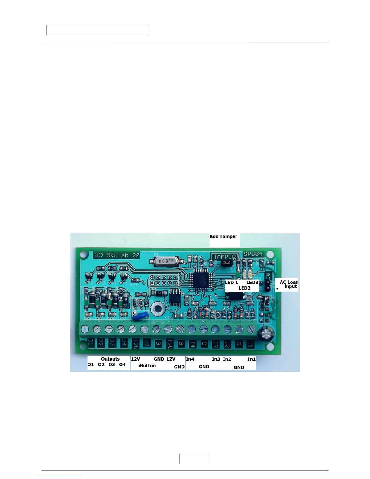
1.0. Main parts:
1 Fixing holes (4 of them)
2 Wired connectors
3 Control LEDs
Outputs O 1 –O 4
LED 1 Green – 1s flash Watchdog , 0,5 s flas Watchdog communication with SPG 1000 is ready
LED 2 Yellow – Armed status
LED 3 Red – Alarm status or communication through the expander socket
4 Expander socket -10 pole at the solder side of the panel
5 ibutton terminal
Fixing holes:
There are 5 pcs of them on the panel at the side of the panel Dimensions: 84 x 40 mm
All fixing holes are isolated, not connected to panel Ground
Wire terminals:
GND Ground
12V +12 VDC in our output terminal
O1-O4 Open collector outputs
In1-In4 Dual end of line resistor inputs for Z1 Z8 (In1 = Z1,Z2, In2= Z3,Z4 )
GND Ground
iButton Data bus for iButton reader
Tamper input Normally closed contact for enclosure or global tamper loop
AC loss input Its a Voltage input ! Requires independent 3 VDC Its designed to work with Sky Laboratories battery backup
power supply Functioning as supervision of AC LED indicator GND and voltage is independent from the panel's own circuit-
WARNING ! The 12 VDC socket is to be used for both supply the SPG84 panel and to power external devices If SPG84 is
not connected to SPG 1000 than power supply must be connected to these terminals If SPG 84 is connected to SPG 1000,
than SPG 1000 will supply SPG 84 and its external devices In this case these terminals could be used to power external
devices Maximal current consumption for external devices are 200mA !
Connecting SPG 1000 and SPG 84 is allowed only at POWER OFF situation !
xpander board socket:
1 GND
2 12V
7 TX TTL 3,3 V serial port
8 RX TTL 3,3 V serial port
Attention !
All connection in this socket is mostly direct to processor Any misuse or inproper voltage will damage the SPG84 This sort of
damage cause of inproper use of the soclet will void Warranty
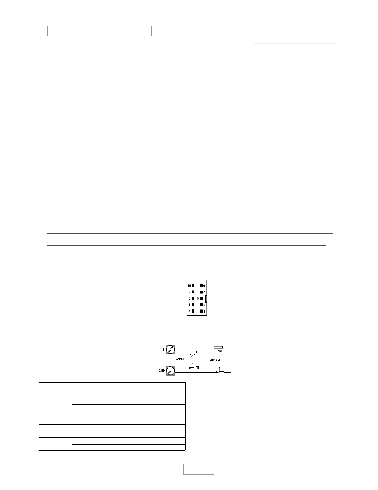
1.1. Input wiring:
Wiring of the End of Line Resistors :
Input: INx Zone nr Resistor value
1Input 1 2,2K
Input 2 3,3K
2Input 3 2,2K
Input 4 3,3K
3Input 5 2,2K
Input 6 3,3K
4Input 7 2,2K
Input 8 3,3K

SPG 84 Installation manual
3.
1.2. Output wiring:
Max current load of any output is limited at 100mA
Total load is 500mA
Output wiring:
Outputs are with LED indicators showing current status
Warning!
Overload outputs will void Warranty
Specification
Power : 10-16 VDC
Standby current: 50 mA
Max current (without outputs): 70 mA
Dimensions LxWxH: 90x 46 20 x mm
Terminal dimensions: Ø2,5 mm
Output load: max 100mA / 12VDC
Input resistors: 2,2K and 3,3K +/-10%
Input status (Only if SPG 1000 connected at SPG 1000 Status page):
Showing current status You may also change output status but changing outputs does not mean that the panel will change
functions Example: if an output is programmed to indicate armed status, the panel will not change its ready status to armed
SPG 84 Installation manual
4.
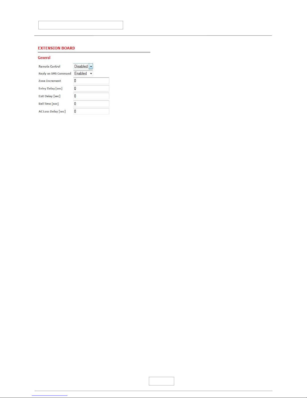
Remote Control:
−Enable: Remote Arming is allowed
−Disable: Remote Arming is disabled
Factory Default: Disabled
•Reply on SMS command:
−Enable: It will enable SPG84 to send reply SMS to command SMS received before
- Disable: SPG will not send any reply SMS
Factory Default: Disabled
•Zone Increment:
The value in this field will be added to the modules own zone numbers Example: If you already have a 16 zone control
panel than set this to 16 By doing so the 1st input of the zone will be numbered and reported as 17th
Factory Default: 0
•ntry delay time:
Valid values: 0-255 sec
Factory Default: 0 sec
•xit delay time:
Valid values: 0-255 sec
Factory Default: 0 sec
•Bell time:
Valid values: 0-255 sec
Factory Default: 0 sec
•AC Loss Delay time:
The time SPG 84 will count until send AC loss report from actual AC loss
Valid values: 0-65000 sec
Factory Default: 0 sec

SPG 84 Installation manual
5.
Inputs
The panel has 4 input , 8 zones with dual end of line resistors Each zone type could be configured here
•Zone :
The number of inputs Z1 Z8
ZT is the enclusure tamper pinout ZA is the AC loss pinout (Attention ! Its an independent 3V DC input !)
Shortcircuit the input (not the zone) will trigger alarm event from both zones
•Zone Types:
−Disabled:
If disabled is selected, no need to install EOL resistors
−Normal:
Immediate zone meaning if the system is Armed, violate
this zone type will activate an alarm immediately
−24Hour:
24 hour zone will activate an alarm , regardless if the system is armed or disarmed
−Delayed:
The system will not alarm during exit and entry delay times if delayed zones are violated for the duration of entry or exit time
All other violation will result alarm
−Technical:
Similar operation of 24 hour zone, but it will not trigger a Fire or Alarm message Its to be used if any sort of contact
information is to be transmitted regardless if armed or disarmed status EG, temperature sensor, pump or other device
activation e t c
−Follower:
A „Follower” zone will act as an „Normal” zone if it has been triggered by itself If a handover zone has triggered after a
„Delay” zone, the remaning delay time will handower from the delay zone to the handower zone
- Stay:
Same as Normal type zone, but in Stay arming it will be bypassed automatically in Stay mode arming If during exit time
the Delayed zone is violated than this zone will be handled as Normal zone type If Delayed zone is not violated during exit
time that this zone will be shunted when exit time cycle is expired
−24h Fire:
Similar operation of 24 hour zone, but it will trigger a Fire Alarm message
−24h Fire trouble: Similar operation of 24 hour zone, but it will trigger a Fire Alarm Trouble message
Factory default: all disabled

SPG 84 Installation manual
.
•Report disabled:
Sending message to central monitoring station
−disabled:
−enabled:
Factory setting: all enabled
•-mai Report:
Sending E-mail message from that particular zone
−disabled:
−enabled:
Factory setting: all disabled
•SMS Report:
Sending SMS message from that particular zone
−disabled:
−enabled:
Factory setting: all disabled
•Name:
You may type here any text in English standard characters, it will be transmitted in E-mail and SMS
Factory setting: all empty
•ZT :
This is the enclosure or global tamper circuit pin No other zonetype can be programmed to this zone input
•ZA:
This is the panel AC loss detection tamper pin No other zonetype can be programmed to this zone input
Dallas Ibutton arming / disarming registration
The SPG 84 can handle up to 8 different dallas ibuttons (type 1990) Each iButton authority level could be set
Dallas ID
This is the hex code of the dallas iButton arming device you may read on the button
Name
You can enter any name here This field will be transmitted in SMS and Emails if programmed
If an unregistered iButton is used, the panel will send an access denied report to the central station via the SPG 1000

SPG 84 Installation manual
7.
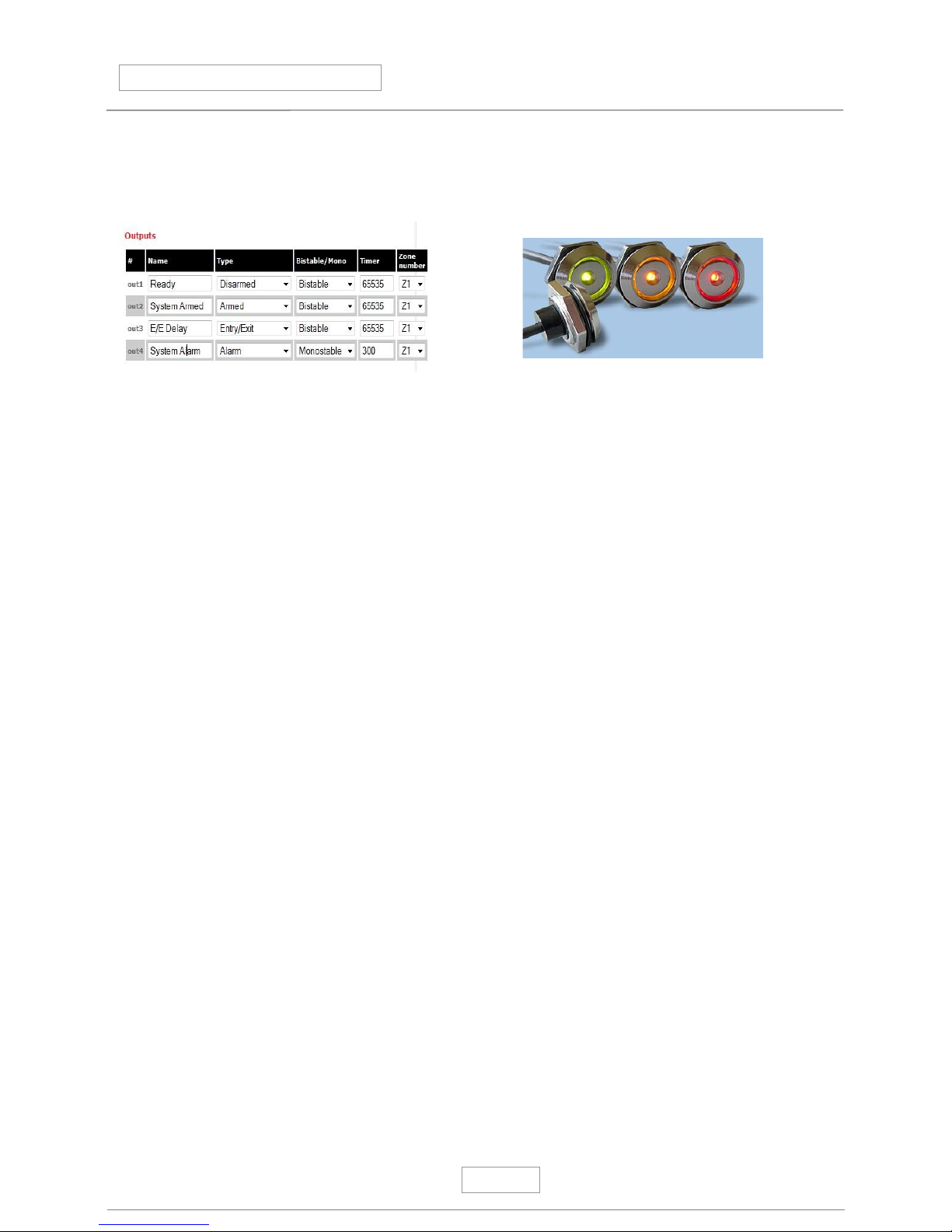
Outputs:
•Output:
There are 4 outputs freely programmable by functions
•Name:
You may enter any description to this zone
Factory default: Empty
•Type:
Output types could be selected here,
−Disabled:
This output is disabled It can not be activated from
anywhere
−Armed:
Will follow the Armed status of the SPG 84
−Disarmed:
Will follow the Disarmed status of the SPG 84
−Alarm:
Will follow the Alarm status of the SPG 84
−24h Alarm
Will follow any 24h Alarm zone status
−Technical
Will follow any Technical zone status
−Tamper :
Will follow any Tamper status of the SPG84
−ntry/ xit:
Will follow the exit entry time status of the SPG
−Communication Fail:
Will be activated if there is a communication failure between the SPG 1000 and the SPG 84
−Zone Follower:
Will follow status of any zone selected
−Server control:
If SPG 84 receives a SMS command either from SMS or directly form SPG 1000 programming web
−AC Loss:
Will be activated if AC loss input is activated
−AC LOSS TIM OUT:
Will be acivated if AC LOSS timeout is expired, and still no AC power
−LOW Battery:
This information is from SPG 1000 only If DC power drops under DC 11,8 V it will be activated
Factory Default : All disabled
•Mode:
Setting the timing of the output
−Monostable:
Will follow the event with the timing as event occures
−Bistable:
Two state output The output will be activated by the event, and will stay in that as timing is set
Factory default: Monostable

SPG 84 Installation manual
8.
•Timer:
Timer for Bistabil output mode
Valid entry: 1-65535sec
Factory default: all 0
•Zone num.:
Only for „Zone follower” output types It will follow the input zone selected
Factory default: „Zone 1”
SMS remote controlling programming (Only with SPG 1000 ):
SPG 1000 and SPG 84 alltogether is could be used for SMS commanding and remote control
If you would like to use these function you need to enable at „Configure” page „SMS Reply mode”
Warning:
Only standard English characters could be used
SMS control:
If the phone nr of the sender of the SMS message to the SPG 84 is registered at USERs you may control SPG 84 with the
following commands :
•SMS format:
OX=Y
Where “O” = output , “X” Number of the output 1 4, “Y” is the required status of the output 0= Out 1=In
Example: O1=1 Turning on Output nr 1
ARM
SPG 84 will be armed by this command module will reply with “ARMED !” answer
DISARM
SPG 84 will be disarmed by this command module will reply with a “DISARMED” answer
ALARM
Will trigger an immediate alarm module will reply with a “ ALARM ACTIVATED” answer
STAT
Requesting status of SPG 84,
Answer is :
[ Z1....Z8] [BOX Tamper] [ACLOSS] [O1=x O2=x O3=x O4=x] [ARM D] [DISARM D] [STAY][ALARM]
Warning:
If SMS messages is stored in your phone and the phone is lost you will risk to let someone to remote control your system
SPG 84 Installation manual
9.
Application guide for wiring and programming for Dallas iButton reader indicators
Setting the outputs the following way iButton reader will indicate status of the SPG 84 expander module:
System Ready : Green
System Armed: Red
Exit/Entry time: Orange
iButton wires : Out 1 - Connected to Out 3
Out 2 - iButton Brown
Out 3 - iButton Green
12V - iButton Yellow
iB - iButton White
GND - iButton Gray
Table of contents
Other Sky Laboratories Control Panel manuals


