Sky Laboratories SPG 1084 User manual

SPG 1084 Installation manual
SPG 1084
Multi functional TCIP/GPRS Security control panel
The security control panel takes convetional security sensors like PIR motion detector, magnetic contacts, glass reak
detectors and it communicates via SIA IP DC9 protocol either in 128 it encrypted or not encrypted format. The SPG 1084
comes with 8 on oard zones and 1 form C relay output and 3open collector output.
SPG 1084 controls ethernet and GPRS channels and capa le of sending e-mail and SMS messages.
Features:
•SIA IP DC9 protocol (SIA TCP/UDP/Encrypted, Closed socket)
•24 hour connect on w th the server (m n.test s gnal nterval s10 sec)
•DHCP / F x IP
•Two server report ng as backup, DYN DNS server
•Web user and nstaller nterface for programm ng or control
•Remote access through Ethernet network.
•F rmware upgrade
•8 programmable zone nputs/ 4 outputs
•8 zone LED keypad for arm g/d sarm ng
•Dallas Button and keysw tch for arm ng and d sarm ng
•E-ma l and SMS send ng
•SMS command ng
•M crophone and loudspeaker output
•RS485 for further opt on

SPG 1084 Installation manual
1.0. ardware description
1.1. Main parts:
1 F x ng holes
2 W re term nals
3 Jumpers
4 L1,L2, L3, L4 Control LEDs
5 SIM-holder
6 Ethernet socket
Fixing oles:
There are 4 pcs of f x ng holes.
Wire terminals:
GND Ground
+IN 12 VDC power
Outputs, nputs, Button reader and keypad outputs
Jumpers:
Factory reset jumpers w ll re set the follow ng parameters:
•Adm n strator password: adm n
•IP address : 192.168.254.253
•Netmask: 255.255.255.0
•Gateway: 0.0.0.0
•HTTPd port: 8080
Reset:
1 Remove power
2 Connect p ns w th the prov d ded shortcut jumper
3 Apply power
4 Remove jumper
J1 Factory reset on Network propert es
J2 Automat c f rmware download thorugh web browser
J3 Factory reset
For f rmware upgrade you may leave the J2 jumper on, ts
not necessary to remove t.
Control LEDs:
L1 GSM STATUS
double flash – GSM s powered
SIM/ or other fault- 0.5s On /0.5s Off
If LED does not l ght – GSM s not ready (for example
no GSM s gnal)
Module s on the GSM network but t can send only
SMS – bl nk n every 4second
Normal status- Bl nk n 1s
SMS send ng- bl nks n 0,1 s
SMS rece v ng – long l ght
GPRS connected- double flash
L2 Commun cat on fault
L3 GSM s gnal qual ty
Max 8 bl nks where 8 s the best.
L4 ACpower w th the Sky Laborator es Power supply only
SIM Card older:
Insert ng or chang ng SIM cards s only allowed f the module
s d sconnected from the power.
Ethernet connector:
A standard RJ45 connector s to be used to connect to the
local network. Connect t only when the module s not
powered, th s way the module w ll get IP address by the
DHCP server. If there s no IP address serv ce ava lable, the
module w ll use the factory default address.
(192.168.254.253)
1.2. Other connectors:
Inputs:
The nputs of SPG 1084 on board can be programmed and
act vated by NO, NC and 2K2 EOL.
If 2K2 EOL s used than e ther short or open c rcu t w ll
tr gger an alarm.
Outputs:
All output s open collector output. Output s l m ted to 150
mA. If you need to draw more current plese use relay and a
d ode as c rcu t protect on as shown here:
SPG 1084 Installation manual
2.0.Specification:
Power supply: 12-16 VDC
Stand by current consumpt on: 80 mA
Max. standby current consumpt on: 150 mA
S ze LxWxH: 85 x100x20mm
Screw term nal s zes: Ø2,5 mm
Ethernet connector Standard RJ45
Commun cat on: 128 b t encrypted
Factory sett ng:
Network mode: Stat c IP
Factory IP-address: 192.168.254.253
Port : 8080
User name : Adm n
Password : Adm n
If you are power ng the external dev ces from the panels +12
V aux l ary term nal, you may not exceed 500 mA current
consumpt on !
3.0. Status web browser
The web page of the panel could be found on the IP address
as prev ously set.
Administrator password:
The entry name and password could be changed here.
Max 15 character could be used.
Factory default: Adm n, Password: Adm n
Warning:
In case of forgett ng the password only reset jumper w ll
reset the factory sett ng.
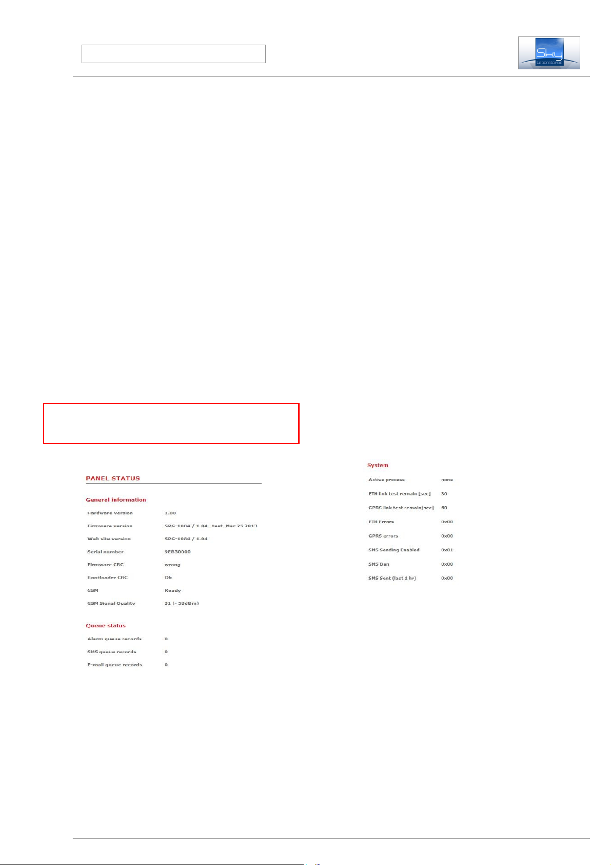
3.1. „Status” page:
Panel Status Information:
•ardware Version
Hardware rev s on nr.
•Firmware Version
The current f rmware ser al nr runn ng n the module.
•Web site version
Vers on of the web page you see now
•Serial Number
Manufactur ng ser al number of the module t s the MAC
address of the panel
•Firmware CRC
After every re-start SPG 1084 controls the consystency of
the program memory. It should d splay “OK”
•Bootloader CRC
After every re-start SPG 1084 controls the consystency of
the bootloader memory. It should d splay “OK”
•GSM Status:
D splays the status of the panel connected to the GSM
network.
•GSM Signal quality:
D splays the status GSM s gnal qual ty- Value 31 s the
h ghest poss ble value.
Panel Status:
•Alarm queue:
Unsent events on the IP network
•SMS queue:
Unsent text messages on the GSM network
•Email queue:
Unsent e-ma ls.
•Active process
Th s s a factory de-bug nformat on. Th s shows the actual
commun cat on or process the SPG 1000 currently
ma nta ns.
•Ethernet link test remain
Rema n ng t me to the next ethernet test t me. Refreshez by
F5 or page reload.
•GPRS test remain
Rema n ng t me to the next GPRS test t me. Refreshez by
F5 or page reload
•ET errors
SPG 1084 Installation manual
Factory debug nformat on.
•GPRS errors
Factory debug nformat on.
•SMS sending enabled
Factory debug nformat on.
•SMS ban
Factory debug nformat on.
•SMS sent 1 hr
Factory debug nformat on. The number of SMS messages
sent n the last hour.
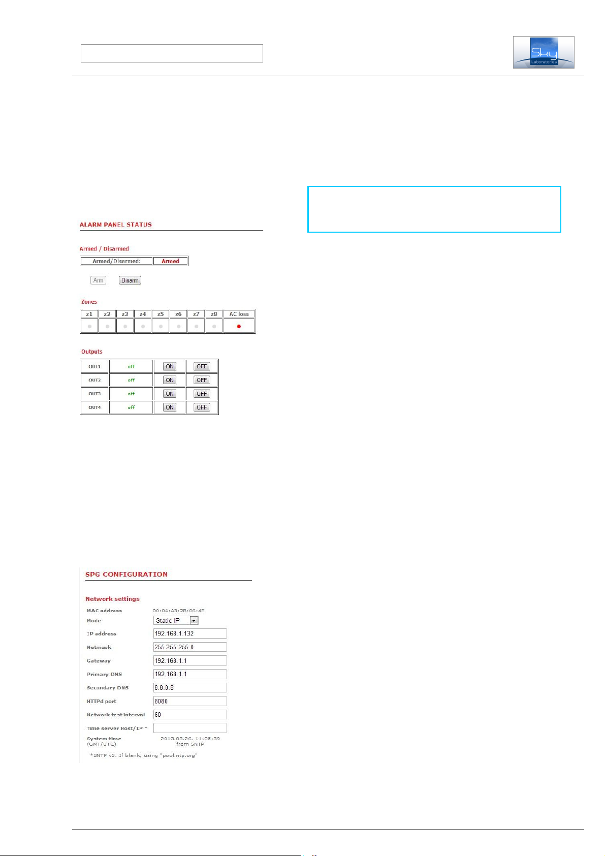
Alarm panel status
The user nformat on and control graph cal nterface to the
panel. It shows on-l ne current status of the zones and
outputs, and f allowed the user can change status of the
alarm and outputs as well.
Programming:
3.2.
After enter the panel by ts pre-set User and Password, you
may change factory default sett ngs.
•MAC address
MAC address can not ba changed.Its always f x.
•Mode:
Network connect on mode could be changed here
−Stat c IP address
−D nam c Address.
Factory Default Stat c
Remark:
If you use dynam c IP, ts st ll adv sed to use one f x IP n
case f DHCP serv ce would be not ava lable. In th s case the
module w ll change to F x IP address.
•IP address:
Th s s the several IP. Th s aress s used for remote
programm ng or remote controll ng.
Factory Default 192.168.254.253
•Netmask:
It s for to be able to d st ngu sh between IP address and
dent f cat on parts for IP packet rece vers.
Factory Default: Empty
•Gateway:
Th s s a dev ce wh ch s n connect on w th more TCP/IP
network. It s for rout ng and forward ng d fferent IP packets
between these networks. For example a router address
w th n the network s des gnated to gateway.
Factory Default : Empty
•Nameserver (primary):
Th s s a name server the server of the serv ce prov der.
Wr te the prov der server address nto th s f eld. ( A router
could be also a name server)
Factory Default: Empty
•Nameserver (secondary):
Th s s a name server the server of the serv ce prov der.
Wr te the prov der server address nto th s f eld. ( A router
could be also a name server)
Factory Default: Empty
Warning:
Secondary name server should be access ble server s nce f
the panel s connected by GPRS, t can not use the router on
the same network as name server
•TTPd port:
The conf g webs te port nr
Factory Default 8080
•Network Test signal interval:
The panel sends test s gnals to the servers n th s g ven
t me per ods.
Factory Default 120
•Time server/ ost
SPG 1084 Installation manual
The panel synchron ze ts nternal clock to an ava lable
publ c t me server on the nternet.
Factory default s „pool.ntp.org”
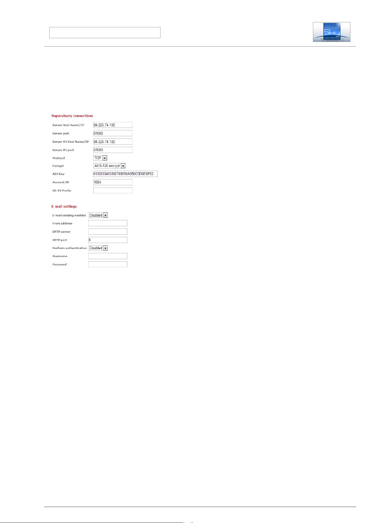
Supervisory connection:
You may set the commun cat on routes of the panel. SPG s
able to send alarm s gnal n a mult ply sequent al paths, IP
commun cat on could be to two d fferent server.
•Server ost Name/IP:
The server locat on of the central mon tor ng stat on. You
may f ll IP address or HOST name.
Factory Default 0:0:0:0
•Server Port number:
The port number of the central mon tor ng server.
Factory Default 0
•#2 Server ost Name/IP:
Secondary server locat on of the central mon tor ng stat on.
You may f ll IP address or HOST name.
Factory Default 0:0:0:0
•#2 Server Port number:
Secondary port number of the central mon tor ng server.T
Factory Default 0
•Protocol:
The requ red protocols could be selected here w th the
central mon tor ng server.
−SIA IP TC2700 (TCP, not enrypted, Close-socket)
−SIA IP UD2700 (UDP, not enrypted, Close-socket)
−SIA IP encrypted TC2700 (TCP, enrypted, Close- soc.)
−SIA IP encrypted UD2700 (UDP, enrypted, Close-soc.)
•AES key:
The encrypt on key should be added here wh ch s g ven
by the central mon tor ng stat on..
Factory Default: Empty
Accunt ID:
SIA account d
Factory Default: Empty
•Prefix:
Th s s prov ded by the central mon tor ng stat on.
Factory Default: Empty
Time Zone:
The module has a bu lt n clock syncron zat on. Select the
t me zone where the panel s nstalled. A modul connects
the „T meserver” per od cally to adjust t m ng. Important !
Syncron zat on could only be done f ethernet connect on s
ava lable, and DNS server s set properly.
Factory Default GMT+00:00
Email:
The module can send e-ma l messages to pre-set
addresses. Here you can adjust globally the e-ma l report ng.
Spec f c sett ngs should be done at the expans on board
programm ng sect on.
•Email:
Enabl ng or d sabl ng any e-ma l commun cat on.
Factory Default: D sabled
•From:
The address of the module e.ma l address.
Factory Default Empty
•SMTP Server:
The ma l server smpt name (prov ded by Internet serv ce
prov ders.
Factory Default Empty
•SMTP Port:
Prov ded by Internet serv ce prov der.
Factory Default Empty
•Authentication:
If your Internet prov der requ res authent cat on you should
set th s accord ngly.
Factory Default: D sabled
•Username:
Username s necessary to access ma l server
.Factory Default Empty

SPG 1084 Installation manual
•Password:
Password s necessary to access the ma l server.
Factory Default Empty
GPRS settings:
W reless GSM commun cat on sett ngs could be made here.
•Access point name (APN):
Prov ded by the GSM prov der
Factory Default: Empty
•Username:
Prov ded by the GSM prov der
Factory Default: Empty
•Password:
Prov ded by the GSM prov der
Factory Default: Empty
•Nameserver (primary):
Prov ded by the GSM prov der. Many prov der does not
requ re any sett ng.
Factory Default: Empty
•Nameserver (secondary):
Prov ded by the GSM prov der. Many prov der does not
requ re any sett ng.
Factory Default: Empty
• Network test signal interval:
Test s gnal nterval only for GPRS transm ss on. From 60
sec.
Factory Default 0
• Balance optimization:
The panel could opt m ze the data traff c for t me or for
data volume, depend ng on your GSM subsc pt on plan.
T me based opt m zat on w ll result that panel w ll spend
the least amount of t me on the GPRS network and w ll
d sconnect as soon as report ng s done. Data based
opt m zat on means that panel w ll rema n connected to the
GPRS network, assum ng that more report ng w ll be
done . Data opt m sat on w ll mean 10-30 m nute
d sconnect on from the GPRS network f there s no
report ng needs.
Factory Default : None
SMS:
SMS global sett ngs could be adjusted n th s sect on.
•SMS sending:
Enabl ng SMS send ng globally.
•
Factory Default D sabled
•Provider source addres:
The GSM prov der source address should be entered
here , from where nformat on s expected and should be
forwarded to an other number (For example the balance
nformat on for pre-pa d GSM serv ces)
Factory Default: Empty
•Forward to:
The ncom ng SMS s forwarded to a pre-set number . Use
nternat onal form for numbers.
Factory Default: Empty
•Forward unknown SMS:
Enables or d sables forward ng SMS from an unknown
number.
Factory Default : Empty
•Sending limit:
Max mum nr of SMS. The counter w ll reset n every hour.
Zero value w ll result unl m ted nr of SMS.
Factory Default 0
•SMS text prefix:
Th s w ll dent fy the panel f you expect more panels to
send sms to the same number.
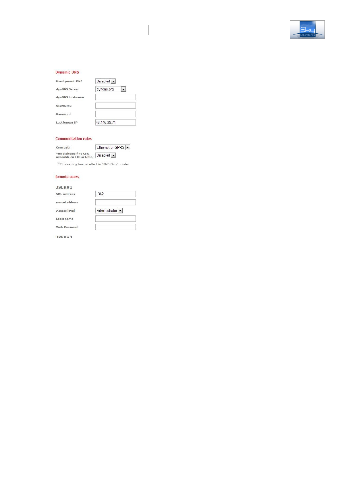
Dynamic DNS:
SPG s enabled for Dynam c DNS commun cat on even f t s
nstalled on a non-f x IP address. Generate a DNS on
a serv ce prov der . In th s case both Internet and GPRS
connect on the module could be remotely accessed.
Enable:
Enables the d nam c IP refresh.
Factory Default: D sable
SPG 1084 Installation manual
•DynDns hostname:
Name you created on DNS server prov der.
Factory Default: Empty
•Username:
Access ng the DNS serv ce
Factory Default: Empty
•Password:
Accessung the DNS serv ce
Factory Default : Empty
•Last known IP:
D splays the last known IP address of the SPG
Communication Rules:
Commun cat on rules of the panel are to be set here.
SPG1000 can handle ndependent commun cat on paths.
Sequence of IP report ng:
2 t mes Ethernet Nr 1 Server address
2 t mes Ethernet Nr 2 server address
GPRS 1 server , GPRS 2 server , n case of
successfull commun cat on SPG 1084 w ll forward
all messages at GPRS channel for 3 m nutes. New
event w ll tr gger the repeat of th s whole sequence.
After unsuccessful commun cat on w ll result 3
m nutes of brake.
If there s only GPRS set as pr mary and only
commun cat on than n case of unsuccessfull event
commun cat on w ll be suspended for 15 m nutes.
The panel w ll send SMS conta n ng the Ademco
Contact ID nformat on from the nternal nputs f
ne ther Ethernet or GPRS commun cat on path s
unava lable.
•GPRS:
Sett ng the pr mary report ng route of the SPG s GPRS.
We suggest to use th s only f Ethernet s not ava lable.
More report ng routes you have the secure the operat on.
SPGs web programm ng page s ava lable through
Ethernet connecton only. If you use GPRS only
commun cat on only local programm ng s ava lable for
you.
•SMS only:
tIf you chose th s opt on the SPG 1084 w ll not send any
alarm reports to central stat on. Only user format SMS
messages . User format sms message content s to be set
at Alarm Funct on sect on of the programm ng.
Factory Default :Ethernet or Gprs
Users
Default programm ng mode (Am n strator) entry to the panel
s Adm n, Adm n (user, password) . Th s rule appl es only f
none of the user log n name and password s f lled out.
If you want to change on the default Adm n strator password
you must use the User nr 1 sect on for the new password.
You may not change Adm nstrator access level on User nr 1.
If you need User level access to be programmed you can do
that n User Nr 2,3 sect on.
•SMS address:
The telephone nr of the user where SMS could be sent-
Always use nternat on format ! e.g +36201111111
Factory Default: Empty
•Email address:
The e-ma l address of the user where e-ma l could be sent-
Factory Default : Empty
•Access level:
Access level of the user
Factory Default: None
•Login Name:
Log n name for the SPG 1084 web page.
Factory Default Empty
•Password:
Log n password of the SPG 1084 web page.
Factory Default Empty

SPG 1084 Installation manual
SMS Control:
Enable: Remote Arm ng/D sarm ng, status request and
output tr gger s allowed by SMS
Factory Default: D sabled
•Reply on SMS command:
Enable: It w ll enable SPG1084 to send reply SMS to
command SMS rece ved before.
- D sable: SPG w ll not send any reply SMS
Factory Default: D sabled
•Arm/Disarm by web:
Enable: It w ll enable SPG1084 to be armed and
d sarmed on the STATUS page web buttons
Factory Default: D sabled
•Notify user on arm/disarm:
Enable: It w ll enable SPG1084 to send SMS to users of
control panel armed/d sarmed status
- D sable: SPG w ll not send SMS about arm status
Factory Default: D sabled
•Chime on keypad buzzer:
Enable: It w ll enable SPG1084 to beep on entry ex t
zone v olat on
Factory Default: D sabled
•Entry delay time:
Val d values: 0-255 sec
Factory Default: 0 sec
•Exit delay time:
Val d values: 0-255 sec
Factory Default: 0 sec
•AC Loss time
Detect on of AC loss of AC loss nput (separate p ns)
Val d values: 0-255 sec
Factory Default: 0 sec
Inputs
The panel has 8 zones w th dual end of l ne res stors. Each
zone type could be conf gured here.
•Zone :
The number of nputs. Z1...Z8
•Zone Types:
−Disabled:
If d sabled s selected, no need to nstall EOL res stors.
-Normal:
Immed ate zone mean ng f the system s Armed, v olate
th s zone type w ll act vate an alarm mmed ately.
−24 our:
24 hour zone w ll act vate an alarm , regardless f the system
s armed or d sarmed.
−Delayed:
The system w ll not alarm dur ng ex t and entry delay t mes f
delayed zones are v olated for the durat on of entry or ex t
t me. All other v olat on w ll result alarm.
-Technical:
S m lar operat on of 24 hour zone, but t w ll not tr gger a
F re or Alarm message. Its to be used f any sort of
contact nformat on s to be transm tted regardless f
armed or d sarmed status. EG, temperature sensor,
pump or other dev ce act vat on e.t.c.
- Follower:
A „Follower” zone w ll act as an „Normal” zone f t has
been tr ggered by tself. If a handover zone has tr ggered
after a „Delay” zone, the reman ng delay t me w ll
handower from the delay zone to the handower zone.
- Stay:
Same as Normal type zone, but n Stay arm ng t w ll be
bypassed automat cally n Stay mode arm ng. If dur ng ex t
t me the Delayed zone s v olated than th s zone w ll be
handled as Normal zone type. If Delayed zone s not v olated
dur ng ex t t me that th s zone w ll be shunted when ex t t me
cycle s exp red.
−24h Fire:

SPG 1084 Installation manual
S m lar operat on of 24 hour zone, but t w ll tr gger a F re
Alarm message.
−24h Fire trouble: S m lar operat on of 24 hour zone,
but t w ll tr gger a F re Alarm Trouble message.
Factory default: all d sabled
- Keyswitch zone:
Th s zone opt on s to handle keysw tch to arm the panel
and d sarm the panel. If the c rcu t s closed the panel s
d sarmed, f open ts armed.
Arm … Disarm … Arm/Disarm zone:
Th s zone opt on s to handle any pulse dev ce l ke push
button. A pulse w ll change status.
•Report disabled:
Send ng message to central mon tor ng stat on
•d sabled:
•enabled:
Factory sett ng: all enabled
•E-mai Report:
Send ng E-ma l message from that part cular zone.
•d sabled:
•enabled:
Factory sett ng: all d sabled
•SMS Report:
Send ng SMS message from that part cular zone
•d sabled:
•enabled:
Factory sett ng: all d sabled
•Name:
You may type here any text n Engl sh standard
characters, t w ll be transm tted n E-ma l and SMS.
Factory sett ng: all empty
•ZA:
Th s s the panel AC loss detect on tamper p n. No other
zonetype can be programmed to th s zone nput.
Dallas Ibutton / Keypad arming / disarming registration
The SPG 1084 can handle up to 8 d fferent dallas buttons
(type 1990), and 8 d fferent keypad code up to 4 d g t code
Each Button author ty level could be set
Dallas ID
Th s s the hex code of the dallas Button arm ng dev ce
you may read on the button.
Name
You can enter any name here. Th s f eld w ll be transm tted
n SMS and Ema ls f programmed.
If an unreg stered Button s used, the panel w ll send an
access den ed report to the central stat on v a the SPG 1084.
The Learn Button key s to learn teach the Button to the
SPG 1084. The ser al nr of the Button w ll be put nto the
next ava lable free space.
Outputs:
•Output:
There are 4 outputs freely programmable by funct ons. Nr
1 s a form C relay output.
•Name:
You may enter any descr pt on to th s zone.

SPG 1084 Installation manual
Factory default: Empty
•Type:
Output types could be selected here,
−Disabled:
Th s output s d sabled. It can not be act vated from
anywhere.
−Armed:
W ll follow the Armed status of the SPG 1084
−Disarmed:
W ll follow the D sarmed status of the SPG 1084
−Alarm:
W ll follow the Alarm status of the SPG 1084
−24h Alarm
W ll follow any 24h Alarm zone status.
−Technical
W ll follow any Techn cal zone status
−Tamper :
W ll follow any Tamper status of the SPG84
−Entry/Exit:
W ll follow the ex t entry t me status of the SPG .
−Communication Fail:
W ll be act vated f there s a commun cat on fa lure
between the SPG 1084 and the central stat on
−Zone Follower:
W ll follow status of any zone selected
−Server control:
If SPG 1084 rece ves a SMS command e ther from SMS
or d rectly form SPG 1084 programm ng web.
−AC Loss:
W ll be act vated f AC loss nput s act vated.
−AC LOSS TIME OUT:
W ll be ac vated f AC LOSS t meout s exp red, and st ll
no AC power.
−LOW Battery:
Th s nformat on s from SPG 1084 only. If DC power
drops under DC 11,8 V t w ll be act vated.
Factory Default : All d sabled
•Mode:
Sett ng the t m ng of the output
•Monostable:
W ll follow the event w th the t m ng as event occures.
•Bistable:
Two state output. The output w ll be act vated by the
event, and w ll stay n that as t m ng s set.
Factory default: Monostable
•Timer:
T mer for B stab l output mode.
Val d entry: 1-65535sec
Factory default: all 0
•Zone num.:
Only for „Zone follower” output types. It w ll follow the nput
zone selected.
Factory default: „Zone 1”
SMS remote controlling
If you would l ke to use these funct on you need to enable at
„Conf gure” page „SMS Reply mode”
Warning:
Only standard Engl sh characters could be used.
SMS control:
If the phone nr of the sender of the SMS message to the
SPG 84 s reg stered at USERs you may control SPG 84
w th the follow ng commands :
•SMS format:
OUTX=Y
Where “O” = output , “X” Number of the output 1...4,
“Y” s the requ red status of the output 0= Out 1=In
Example: OUT1=1 Turn ng on Output nr 1
ARM
SPG 1084 w ll be armed by th s command module
w ll reply w th “ARMED !” answer
DISARM
SPG 1084 w ll be d sarmed by th s command module
w ll reply w th a “DISARMED” answer
STAT
Request ng status of SPG 1084
Warning:
If SMS messages s stored n your phone and the phone s
lost you w ll r sk to let someone to remote control your
system.

SPG 1084 Installation manual
Keypad functions
The keypad s w red to the SPG 1084 as follows:
keypad SPG 1084
+ 12V - K+
GND - GND
DAT - DAT
CLK - CLK
Fire, Medical, Panic buttons
By press ng the F, M P buttons w ll act vate a central stat on
commun cat on.
To add or change user codes and iButtons
use the following commands
*1<master code>*<user pos t on><new code>#
Example : *11234*25555#
Th s w ll set the second user keypad code 5555.
Delete a user code:
*1<master code>*<user pos t on>#
You can not delete a MASTER CODE
Dallas Button learn ng:
*3<master code>*<user pos t on>#
Present your new Button after press ng the # key.
Dallas Button delete:
*2<master code>*<user pos t on>#
New Button w ll Arm-D sarm by default, but t can be
changed on the webs te.
Suggested Application guide for wiring and
programming for Dallas iButton reader
indicators
Sett ng the outputs the follow ng way Button reader w ll
nd cate status of the SPG 1084 module:
System Ready : Green
System Armed: Red
Ex t/Entry t me: Orange
Button w res : Out 1 - Connected to Out 3
Out 2 - Button Brown
Out 3 - Button Green
12V - Button Yellow
B - Button Wh te
GND - Button Gray

SPG 1084 Installation manual
Contact ID codes used :
1400 D sarm (Open)
1401 Open by User by user
3400 Close
3401 Close by user
1454 Fa led to close
130 Burglary
133 24 Hour (Safe)
134 Entry/Ex t
132 Follower zone alarm
150 24 Hour Non-Burglary
110 F re
200 F re fault
1409 Keysw tch - open
3409 Keysw tch - close
137 Tamper
301 AC loss
1115 Keypad-F / Pull Stat on
1100 Keypad-M / Med cal
1101 Keypad-P / Personal
302 low bat
358 ETH fa l
359 GPRS fa l
333 Extens on Board fa l
305 System Reset
Table of contents
Other Sky Laboratories Control Panel manuals


