2
1Safety information........................................................................................................................................................3
1.1 Safety................................................................................................................................................................ 3
1.2 230V AC............................................................................................................................................................ 3
1.3 Back-up batteries .............................................................................................................................................. 3
1.4 Application......................................................................................................................................................... 3
1.5 Cable routing and electrical connection............................................................................................................. 3
2Structure of the smoke panel......................................................................................................................................4
3
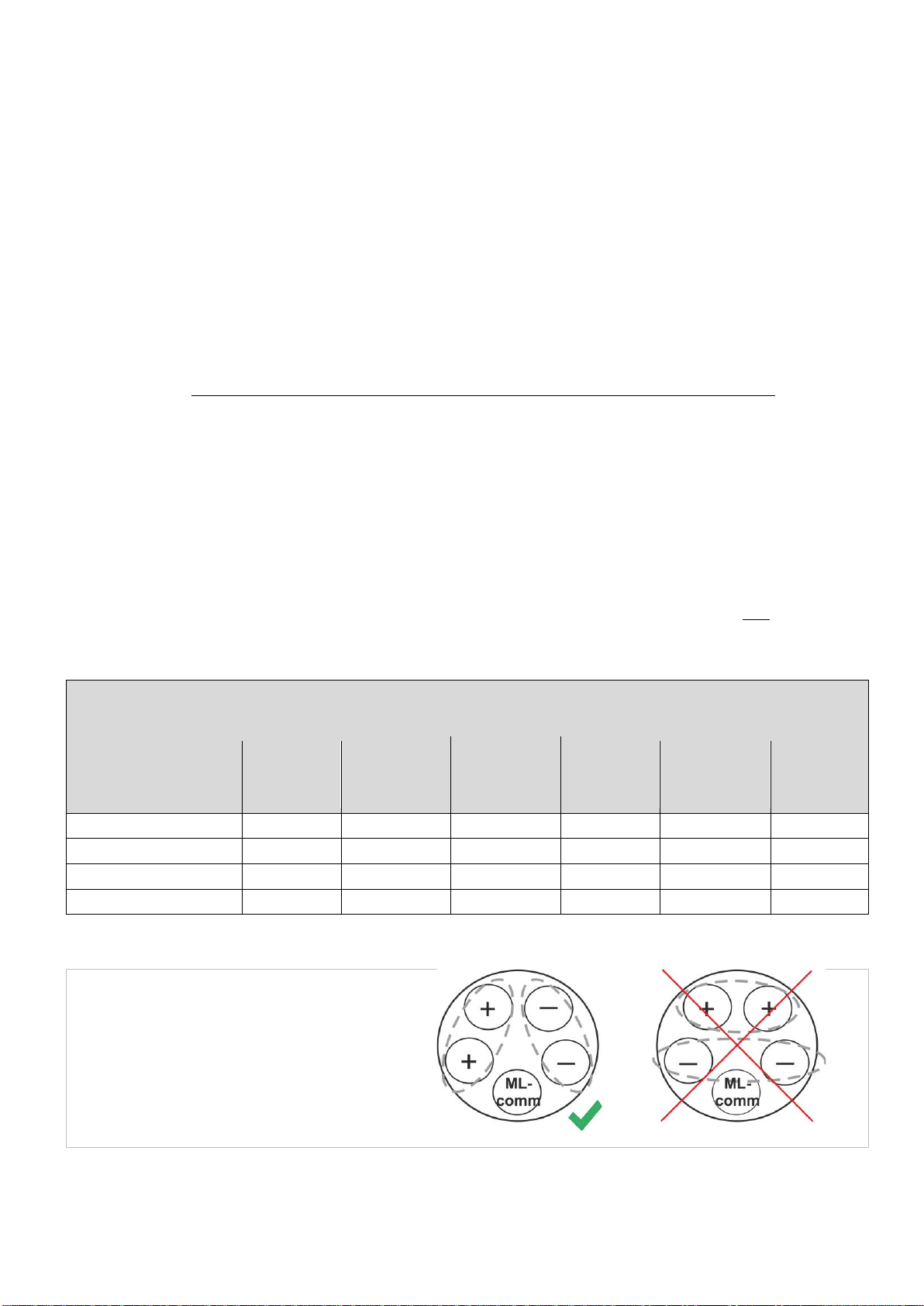
Max numbers of actuators per motor line and panel
....................................................................................................4
4Accessories and spare parts ......................................................................................................................................5
5Technical data..............................................................................................................................................................6
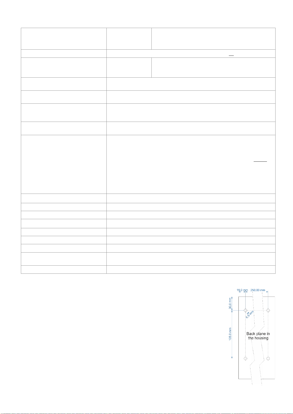
6Mounting.......................................................................................................................................................................7
7Installation....................................................................................................................................................................8
7.1 Cable routing..................................................................................................................................................... 8
7.2 Cables into housing........................................................................................................................................... 8
7.3 Connection of safety earth wire and 230V AC................................................................................................... 8
7.4 Installation of the break glass unit, ventilation keypad and smoke detector...................................................... 8
7.5 Assembly instructions........................................................................................................................................ 8
8Cable dimensioning.....................................................................................................................................................9
8.1 Maintaining the cable functions......................................................................................................................... 9
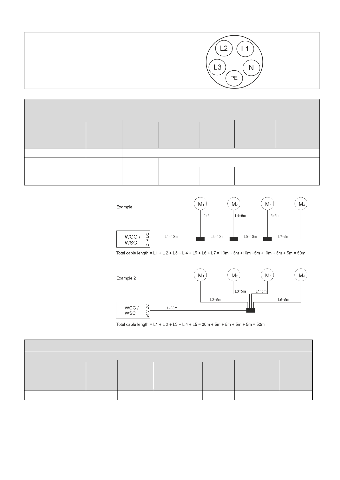
8.2 Max. cable Length............................................................................................................................................. 9
8.2.1 Formula for the calculation of the maximum actuator cable length ...............................................................9
8.2.2 Max cable length –±24V standard actuators ................................................................................................9
8.2.3 Max cable length –actuators with MotorLink®...............................................................................................9
8.2.4 Max cable length –Pyrotechnic gas generator ...........................................................................................10
9Cable plan for connection to WSC 104 ....................................................................................................................11
10 Description of card and mains connection..............................................................................................................11
10.1 Mains connection and power supply (WCA 1P1) .............................................................................................11
10.2 Main card WSA 1SS.........................................................................................................................................12
11 DIP switch configuration...........................................................................................................................................18
12 Back-up batteries.......................................................................................................................................................19
13 Configuration of panel...............................................................................................................................................19
13.1.1 Motor line ....................................................................................................................................................19
13.1.2 Smoke zone ................................................................................................................................................19
13.1.3 Local input...................................................................................................................................................19
13.1.4 Local output.................................................................................................................................................20
14 Fault detection via LED..............................................................................................................................................20
14.1 Fault detection on the smoke panel..................................................................................................................20
14.2 Fault indication on break glass unit..................................................................................................................21
15 Hardware error ...........................................................................................................................................................21
15.1 Error on the Power supply................................................................................................................................21
15.1.1 Blown fuses –6.3A slow .............................................................................................................................22
16 Commissioning and test run.....................................................................................................................................22
16.1 The control ventilation panel is completely installed, without the operating voltage applied.............................22
16.2 With mains voltage, without accumulator.........................................................................................................22
16.3 With mains voltage, with accumulator..............................................................................................................22
16.4 Ventilation keypad............................................................................................................................................22
16.5 Break glass unit WSK 50x................................................................................................................................22
16.6 Smoke detectors ..............................................................................................................................................23
16.7 Emergency power supply test..........................................................................................................................23
16.8 Wind/rain detector............................................................................................................................................23
17 Maintenance ...............................................................................................................................................................23
17.1 Maintenance agreements.................................................................................................................................23
17.2 Replacement 1SS card ....................................................................................................................................24
18 Declaration of Conformity and Declaration of Performance ..................................................................................24