SKYSMotor 3DM2283T User manual


Full Digital Stepper Drive 3DM2283T
Table of Contents
1. Introduction, Features and Applications...................................................................................................................... 1
Introduction..............................................................................................................................................................1
Features....................................................................................................................................................................1
Applications............................................................................................................................................................. 1
2. Specifications...............................................................................................................................................................1
Electrical Specifications (Tj = 25℃/77℉)..............................................................................................................1
Operating Environment and other Specifications....................................................................................................2
Mechanical Specifications (unit: mm [1inch=25.4mm]).........................................................................................2
Elimination of Heat..................................................................................................................................................2
3. Pin Assignment and Description..................................................................................................................................3
Connector P1 Configurations...................................................................................................................................3
Connector P2 Configurations...................................................................................................................................3
RS232 Communication Port.................................................................................................................................... 4
4. Control Signal Connector (P1) Interface..................................................................................................................... 4
5. Connecting the Motor.................................................................................................................................................. 5
6. Power Supply Selection............................................................................................................................................... 5
7. Selecting Microstep Resolution and Drive Output Current.........................................................................................5
Microstep Resolution Selection............................................................................................................................... 5
Current Settings....................................................................................................................................................... 6
Dynamic Current Setting......................................................................................................................................... 6
Standstill Current Setting.........................................................................................................................................6
Motor auto-identification and parameter auto-configuration.................................................................................. 6
8. Wiring Notes................................................................................................................................................................6
9. Typical Connection......................................................................................................................................................7
10. Sequence Chart of Control Signals............................................................................................................................7
11. Protection Functions.................................................................................................................................................. 8
www.skysmotor.co.uk

Full Digital Stepper Drive 3DM2283T
12. Frequently Asked Questions......................................................................................................................................9
Problem Symptoms and Possible Causes................................................................................................................ 9
www.skysmotor.co.uk

Full Digital Stepper Drive 3DM2283T
1
1. Introduction, Features and Applications
Introduction
The 3 DM2283T is a fully digital stepper drive developed with advanced DSP control algorithm based on the
latest motion control technology. It has achieved a unique level of system smoothness, providing optimal torque and
nulls mid-range instability. Its motor auto-identification and parameter auto-configuration feature offers quick
setup to optimal modes with different motors. Compared with traditional analog drives, 3DM2283T can drive a stepper
motor at much lower noise, lower heating, and smoother movement. Its unique features make 3DM2283T an ideal
choice for high requirement applications.
Features
Anti-Resonance provides optimal torque and nulls mid-range instability
Motor auto-identification and parameter auto-configuration technology, offers optimal responses with different
motors
Multi-Stepping allows a low resolution step input to produce a higher microstep output, thus offers smoother motor
movement
Microstep resolutions programmable, from 200 to 25600. It can also be set via DIP switches.
Soft-start with no “jump” when powered on
Supply voltage up to 240 VAC
Output current programmable, from 2.1A to 11.7A. It can also be set via DIP switches.
Pulse input frequency up to 200 KHz, TTL compatible and optically isolated input
Automatic idle-current reduction
Suitable for 3-phase motors
Support PUL/DIR and CW/CCW modes
Over-voltage, Under-voltage, over-current, phase-error protections
Applications
Suitable for a wide range of stepping motors, size from NEMA34 to 42. It can be used in various kinds of machines,
such as X-Y tables, engraving machines, labeling machines, laser cutters, pick-place devices, and so on. Particularly
adapt to the applications desired with low noise, low heating, high speed and high precision.
2. Specifications
Electrical Specifications (Tj = 25℃/77℉)
Parameters
DM2282T
Min Typical Max Unit
Output Peak Current 2.1 - 11.7 A
Input Voltage 176 220 253 VAC
Logic Signal Current 7 10 16 mA
Pulse input frequency 0 - 200 kHz
Pulse Width 2.5 - - uS
Isolation resistance 500 MΩ
www.skysmotor.co.uk
Full Digital Stepper Drive 3DM2283T
2
Operating Environment and other Specifications
Cooling
Operating Environment
Storage Temperature
Weight
Natural Cooling or Forced cooling
Environment Avoid dust, oil fog and corrosive gases
Ambient Temperature 0℃ - 50℃
Humidity 40%RH -90%RH
Operating Temperature 45℃Max
Vibration 10-55Hz/0.15mm
-20℃ - 65℃
Approx. 1.3Kg(45.86oz)
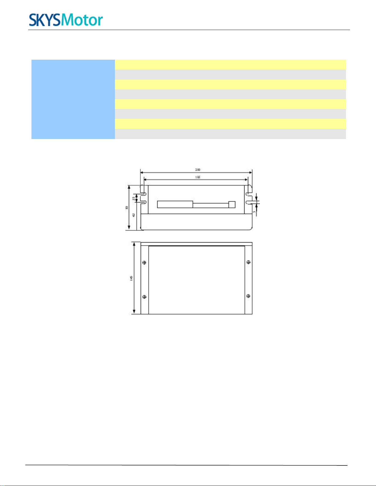
Mechanical Specifications (unit: mm [1inch=25.4mm])
Figure 1: Mechanical specifications
*Recommend use side mounting for better heat dissipation
Elimination of Heat
Drive’s reliable working temperature should be <45℃(113 ℉), and motor working temperature should be
<80℃(176℉);
It is recommended to use automatic idle-current mode, namely current automatically reduce to 50% when motor
stops, so as to reduce drive heating and motor heating;
It is recommended to mount the drive vertically to maximize heat sink area. Use forced cooling method to cool
the system if necessary.
www.skysmotor.co.uk

Full Digital Stepper Drive 3DM2283T
3
3. Pin Assignment and Description
The 3DM2283T has two connectors, connector P1 for control signals connections, and connector P2 for power and
motor connections. The following tables are brief descriptions of the two connectors. More detailed descriptions of
the pins and related issues are presented in section 4, 5, 9.
Connector P1 Configurations
Pin Function
Details
DIR-
DIRsignal: In single-pulse mode, this signal has low/high voltage levels, representing two
directions of motor rotation; in CW/CCW mode (software configurable), this signal is counter-
clock (CCW) pulse, active both at high level and low level. For reliable motion response, DIR
signal should be ahead of PUL signal by 5μs at least. 4-5V when DIR-HIGH, 0-0.5V when
DIR-LOW. Please note that rotation direction is also related to motor-driver wiring match.
Exchanging the connection of two wires for a coil to the driver will reverse motion direction.
Series connect resistors for current-limiting when +12V or +24V used. The same as DIR and ENA
signal.
DIR+
PUL-
Pulse signal: In single pulse (pulse/direction) mode, this input represents pulse signal, each
rising or falling edge active ; in CW/CCW mode (software configurable),this input represents
clockwise(CW) pulse, active both at high level and low level. 4-5V when PUL-HIGH, 0-0.5V when
PUL-LOW. For reliable response, pulse width should be longer than 2.5μs.
PUL+
ENA-
Enablesignal: This signal is used for enabling/disabling the driver. High level (NPN control
signal, PNP and differential control signals are on the contrary, namely low level for enabling.)
for enabling the driver and low level for disabling the driver. Usually left UNCONNECTED
(ENABLED).
ENA+
FAULT+
Fault Signal: OC output signal, active when one of the following protection is activated: over-voltage,
over current, low voltage, phase error and over-temperature. This port can sink or source 20mA
current at 24V. In default, the resistance between FAULT+ and FAULT- is high impedance in normal
operation and become low when 3DM2283T goes into error.
FAULT-
Connector P2 Configurations
Pin Function
Details
PE
Recommend connect this port to the ground for better safety.
L
Power supply inputs. If AC input, recommend use isolation transformers with theoretical output
voltage of 176~253VAC.
N
NC
No Connection
U
Motor Phase U
V
Motor Phase V
W
Motor Phase W
www.skysmotor.co.uk
Full Digital Stepper Drive 3DM2283T
4
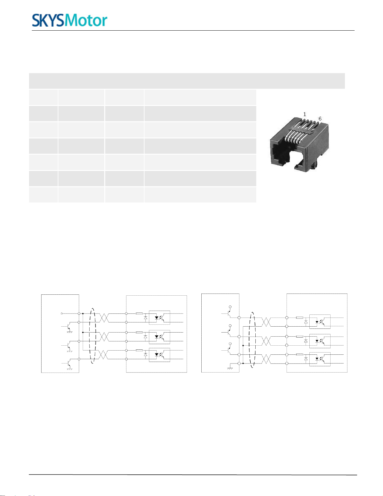
RS232 Communication Port
The RS232 communication port is used to configure the 3DM2283T’s peak current, microstep, active level, current loop
parameters and anti-resonance parameters.
RS232 Communication Port – RJ11
Pin
Name
I/O
Description
1
NC
-
Not connected.
2
+5V
O
+5V power output.
3
TxD
O
RS232 transmit.
4
GND
GND
Ground.
5
RxD
I
RS232 receive.
6
NC
-
Not connected.
4. Control Signal Connector (P1) Interface
The 3DM2283T can accept differential and single-ended inputs (including open-collector and PNP output). The
3DM2283T has 3 optically isolated logic inputs which are located on connector P1 to accept line drive control signals.
These inputs are isolated to minimize or eliminate electrical noises coupled onto the drive control signals.
Recommend use line drive control signals to increase noise immunity of the drive in interference environments. In
the following figures, connections to open-collector and PNP signals are illustrated.
C
on
t
ro
lle
r
Dr
i
v
e
C
on
t
ro
lle
r
Drive
VCC
PUL
DIR
ENABLE
PUL+
PUL-
DIR+
DIR-
ENA+
ENA-
PUL
DIR
ENABLE
PUL+
VCC PUL-
DIR+
DIR-
ENA+
ENA
www.skysmotor.co.uk
Full Digital Stepper Drive 3DM2283T
5
Figure 3: Connections to open-collector Figure 4: Connection to PNP signal (common-cathode)
signal (common-anode)
5. Connecting the Motor
The DM2282T can drive 3-phase hybrid stepping motors with 3-wires or 6-wires,1.2°step-angle.
6. Power Supply Selection
The power supply voltage can work normally between the voltage range specified by the driver. The 3DM2283T is
directly powered by AC. It is recommended that the user use the highest voltage lower than the driver's specified voltage
to avoid the grid fluctuation exceeding the driver voltage operating range.
To reduce costs, two or three drivers can share a single power supply, but the power of power supply should be large
enough.
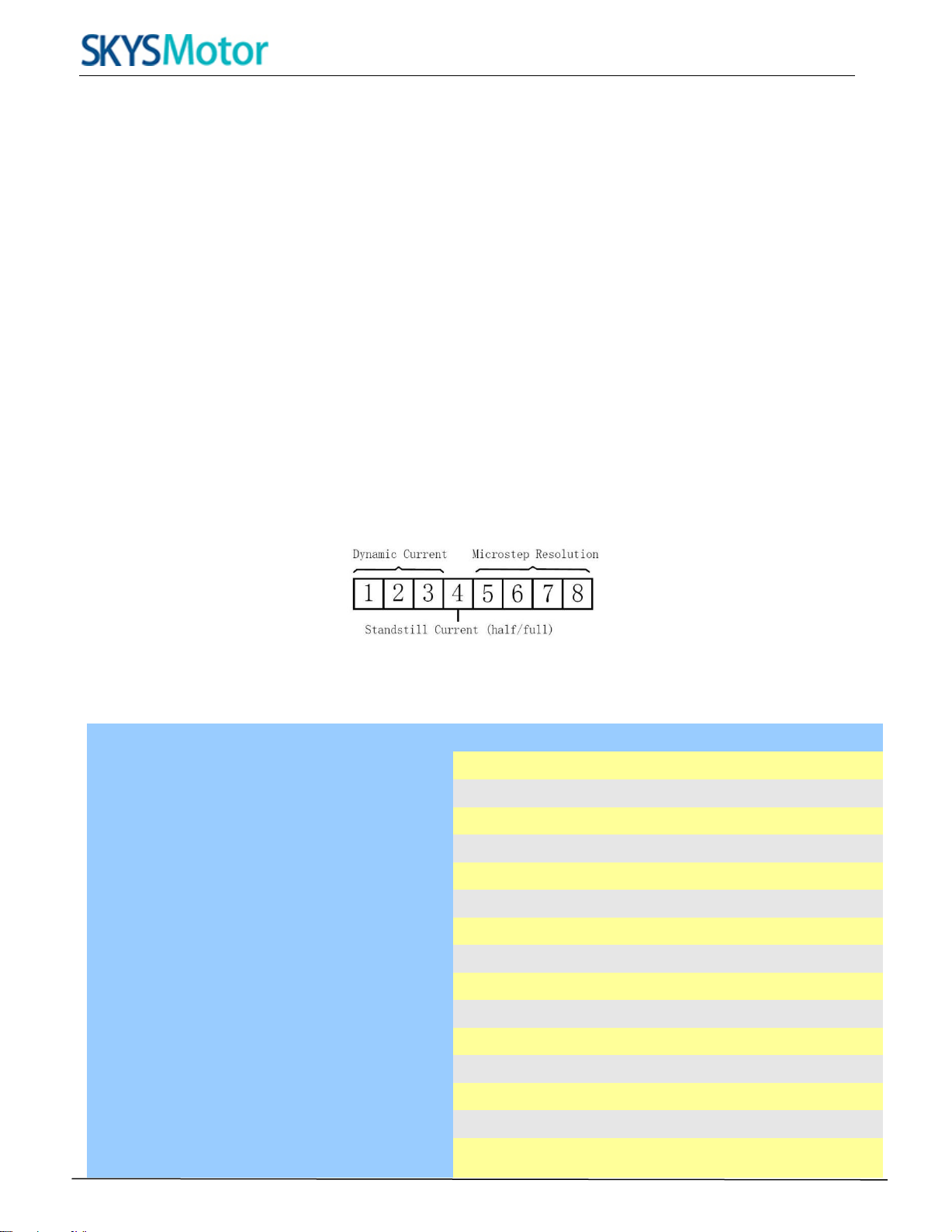
7. Selecting Microstep Resolution and Drive Output Current
This drive uses an 8-bit DIP switch to set microstep resolution, and motor operating current, as shown
below:
Microstep Resolution Selection
Microstep resolution is set by SW5, 6, 7, 8 of the DIP switch as shown in the following table:
Steps/rev. SW5 SW6 SW7 SW8
200
ON ON ON ON
400
OFF ON ON ON
1600
ON OFF ON ON
3200
OFF OFF ON ON
6400
ON ON OFF ON
12800
OFF ON OFF ON
25600
ON OFF OFF ON
500
OFF OFF OFF ON
1000
ON ON ON OFF
1200
OFF ON ON OFF
2000
ON OFF ON OFF
4000
OFF OFF ON OFF
5000
ON ON OFF OFF
6000
OFF ON OFF OFF
8000
ON OFF OFF OFF
www.skysmotor.co.uk

Full Digital Stepper Drive 3DM2283T
6
OFF OFF OFF OFF
10000
Current Settings
For a given motor, higher drive current will make the motor to output more torque, but at the same time causes
more heating in the motor and drive. Therefore, output current is generally set to be such that the motor will not
overheat for long time operation. Since parallel and serial connections of motor coils will significantly change
resulting inductance and resistance, it is therefore important to set drive output current depending on motor phase
current, motor leads and connection methods. Phase current rating supplied by motor manufacturer is important in
selecting drive current, however the selection also depends on leads and connections.
The first three bits (SW1, 2, 3) of the DIP switch are used to set the dynamic current. Select a setting closest to
your motor’s required current.
Dynamic Current Setting
Peak Current RMS Current SW1 SW2 SW3
Default Default
3.1A 2.2A
4.5A 3.2A
5.9A 4.2A
7.3A 5.2A
8.9A 6.3A
10.1A 7.2A
11.7A 8.3A
OFF OFF OFF
ON OFF OFF
OFF ON OFF
ON ON OFF
OFF OFF ON
ON OFF ON
OFF ON ON
ON ON ON
Notes: Due to motor inductance, the actual current in the coil may be smaller than the dynamic current
setting, particularly under high speed condition.
Standstill Current Setting
SW4 is used for this purpose. OFF meaning that the standstill current is set to be half of the selected dynamic
current, and ON meaning that standstill current is set to be the same as the selected dynamic current.
The current automatically reduced to 50% of the selected dynamic current one second after the last pulse.
Motor auto-identification and parameter auto-configuration
The drive will operate the function of motor auto-identification and parameter auto-configuration when power on,
and calculate the optimal parameter using for current control after this processing,, then the stepper motor can
output optimal torque.
8. Wiring Notes
In order to improve anti-interference performance of the drive, it is recommended to use twisted pair shield
cable.
To prevent noise incurred in PUL/DIR signal, pulse/direction signal wires and motor wires should not be tied
www.skysmotor.co.uk

Full Digital Stepper Drive 3DM2283T
7
up together. It is better to separate them by at least 10 cm, otherwise the disturbing signals generated by motor
will easily disturb pulse direction signals, causing motor position error, system instability and other failures.
If a power supply serves several drives, separately connecting the drives is recommended instead
of daisy-chaining.
It is prohibited to pull and plug connector P2 while the drive is powered ON, because there is high current
flowing through motor coils (even when motor is at standstill). Pulling or plugging connector P2 with power
on will cause extremely high back-EMF voltage surge, which may damage the drive.
9. Typical Connection
A complete stepping system should include stepping motor, stepping drive, power supply and controller
(pulse generator). A typical connection is shown as figure 10.
Figure 10: Typical
connection
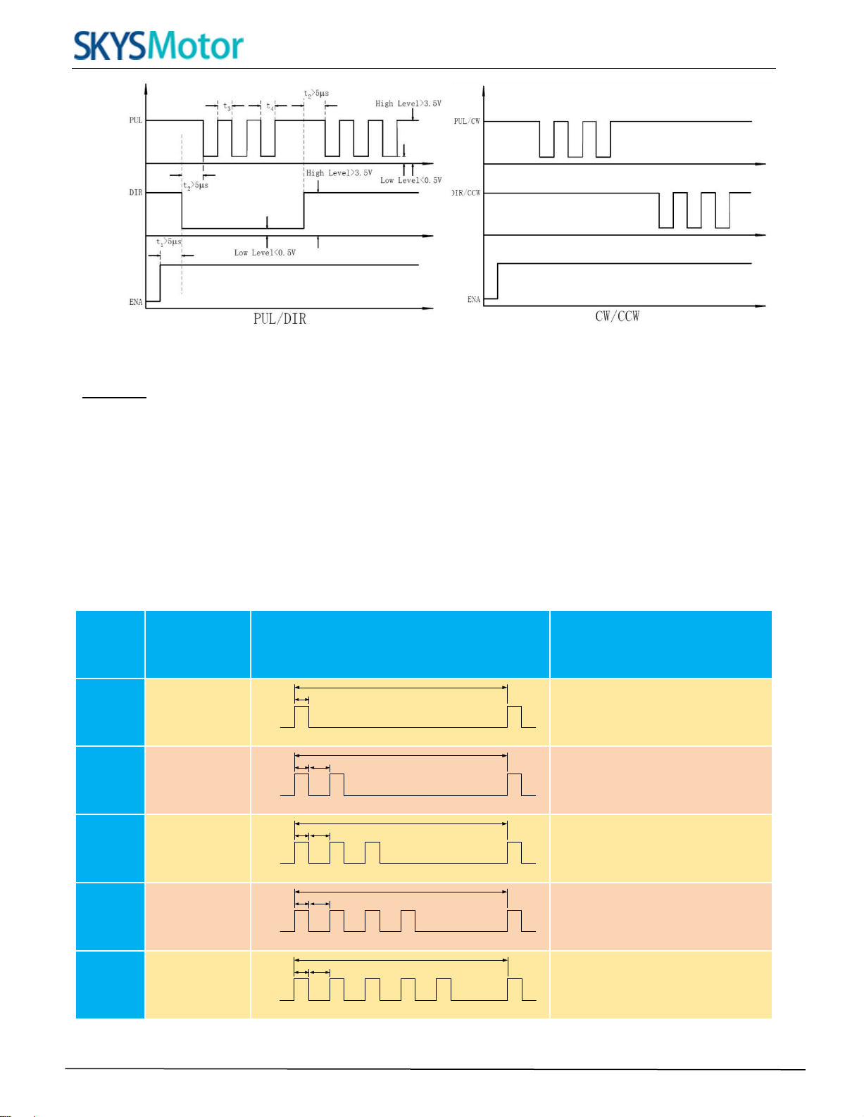
10. Sequence Chart of Control Signals
In order to avoid some fault operations and deviations, PUL, DIR and ENA should abide by some rules, shown
asfollowing diagram:
www.skysmotor.co.uk
Full Digital Stepper Drive 3DM2283T
8
Figure 11: Sequence chart of control signals
Remark :
a)t1: ENA must be ahead of DIR by at least 5s. Usually, ENA+ and ENA- are NC (not connected). See
“Connector P1 Configurations” for more information.
b)t2: DIR must be ahead of PUL effective edge by 5s to ensure correct direction;
c)t3: Pulse width not less than 2.5s;
d)t4: Low level width not less than 2.5s.
11. Protection Functions
To improve reliability, the drive incorporates some built-in protections features.
Priority
Time(s) of
Blink
Sequence wave of RED LED
Description
1st
1
0.2S
3S
Over-current Protection
2nd
2
0.2S 0.3S
3S
Over-voltage Protection
3rd
3
0.2S 0.3S
3S
Low-voltage Protection
4th
4
0.2S 0.3S
3S
Phase Error Protection
5th
5
0.2S 0.3S
3S
Over Temperature Protection
When above protections are active, the motor shaft will be free or the red LED blinks. Reset the drive by repowering
www.skysmotor.co.uk

Full Digital Stepper Drive 3DM2283T
9
it to make it function properly after removing above problems.
12. Frequently Asked Questions
In the event that your drive doesn’t operate properly, the first step is to identify whether the problem is electrical or
mechanical in nature. The next step is to isolate the system component that is causing the problem. As part of
this process you may have to disconnect the individual components that make up your system and verify that they
operate independently. It is important to document each step in the troubleshooting process. You may need this
documentation to refer back to at a later date, and these details will greatly assist our Technical Support staff
in determining the problem should you need assistance.
Many of the problems that affect motion control systems can be traced to electrical noise, controller software errors,
or mistake in wiring.
Problem Symptoms and Possible Causes
Symptoms Possible Problems
Motor is not rotating
Motor rotates in the wrong direction
The drive in fault
Erratic motor motion
Motor stalls during acceleration
Excessive motor and drive heating
No power
Microstep resolution setting is wrong
DIP switch current setting is wrong
Fault condition exists
The drive is disabled
Motor phases may be connected in reverse
DIP switch current setting is wrong
Something wrong with motor coil
Control signal is too weak
Control signal is interfered
Wrong motor connection
Something wrong with motor coil
Current setting is too small, losing steps
Current setting is too small
Motor is undersized for the application
Acceleration is set too high
Power supply voltage too low
Inadequate heat sinking / cooling
Automatic current reduction function not being utilized
Current is set too high
www.skysmotor.co.uk
Table of contents
Popular Control Unit manuals by other brands

Kessel
Kessel Aqualift Comfort 230V Duo Instructions manual for installation, operation and maintenance

LG
LG PWFSA3 user manual

Gossen MetraWatt
Gossen MetraWatt SMARTCONTROL ECS installation instructions

LOVATO ELECTRIC
LOVATO ELECTRIC GEX69 C Series manual

Moeller
Moeller Xcomfort CAEE-02/01 Assembly instructions

Revox
Revox Re:source user manual


