SlatPro SLAG HOG 67182 NSH3 User manual

User Manual
67182 NSH3
Slag Removal Tool for narrow slat spacing for use on laser
cutting machines with minimum 1.25” between slats
Slatpro LLC
4757 Mustang Circle
Mounds View, MN USA
Phone: +1 763-452-4550
Fax: +1 763-452-4560
www.slatpro.com
1. Safety
1.1 General Safety Instructions
ΔWARNING! Read all safety warnings and all instructions. Failure to follow the warnings
and instructions may result in electric shock, fire and/or serious injury.
Save all warnings and instructions for future reference.
1.2 Slaghog Specific Safety Warnings and Instructions
A. Unplug tool from power before performing maintenance on Slaghog
B. Use protective equipment. Always wear safety glasses when working with the machine.
Protective clothing is recommended such as dust mask, gloves, steel toed non-slip footwear
and hearing protection.
C. Do not expose tool to wet conditions or operate in damp environment
D. Power cord to be kept clear from working range of machine. Always lead cord away from
machine. Do not apply tension to power cord.
E. Switch tool off immediately if it stalls. Lift cutters out of slats before restarting.
2. Supporting Information
2.1 Conditions of use
The tool is only to be use for removing the slag from slats on laser cutting machines where the slats
create a horizontal plane and the vertical slat sides are cleaned. The slats may be steel, stainless
steel or copper. Not to be used in wet areas or outside.
WARNING
2.2 Mains Connection
Connect only to single-phase AC voltage as indicated on the rating sticker. Plug-in receptacle to have
ground contact with current capacity exceeding the tools rating.
Only plug in when tool switches are off.
2.3 Maintenance
The ventilation slots must be kept clear or over-heating may result.
If the supply cord is damaged it must only be replaced by qualified personnel. Only use Slatpro replacement
parts when performing repairs or maintenance.
2.4 Technical Information
TechnicalData
SlagHogSlagRemovalTool
Productioncode 67182‐120V 67182‐230V
Voltage 120Va.c. 230Va.c.
Current 10amps 6amps
Frequency 50/60hz
Weight 47lb 21.4kg
NoiseInformation
MeasuredvaluesdeterminedaccordingtoEN60745.Typically,theA
weightednoiselevelsofthetoolare:
Soundpressurelevel(UncertaintyK=3db(A)) 90db(A)
Soundpowerlevel(UncertaintyK=3db(A)) 101db(A)
WearearProtectors!
Vibrationinformation
Vibrationtotalvalues(triaxialvectorsum)determinedaccordingto
EN60745
Connectonlytoasingle‐phaseACcurrentsupplyandonlytomains
voltagespecifiedontheratingplate
Vibrationemissionvaluea
h,d
4.3m/s
2
UncertaintyK= 1,5m/s
2
Warning
The Vibration emission level given in this information sheet has been measured in accordance with a standardized
test given in EN 60745 and may be used to compare one tool with another. It may be used for a preliminary
assessment of exposure.
The declared vibration emission level represents the main applications of the tool. However, if the tool is used for
different applications, with different accessories or poorly maintained, the vibration emission may differ. This may
significantly increase the exposure level over the working period.
An estimation of level of exposure to vibration should also take into account the times when the tool is switched off
or when it is running but not actually doing the job. This may significantly reduce the exposure level over the total
working period.
Identify additional safety measures to protect the operator from the effects of vibrations such as: maintain the tool
and the accessories, keep the hands warm, organization of work patterns.
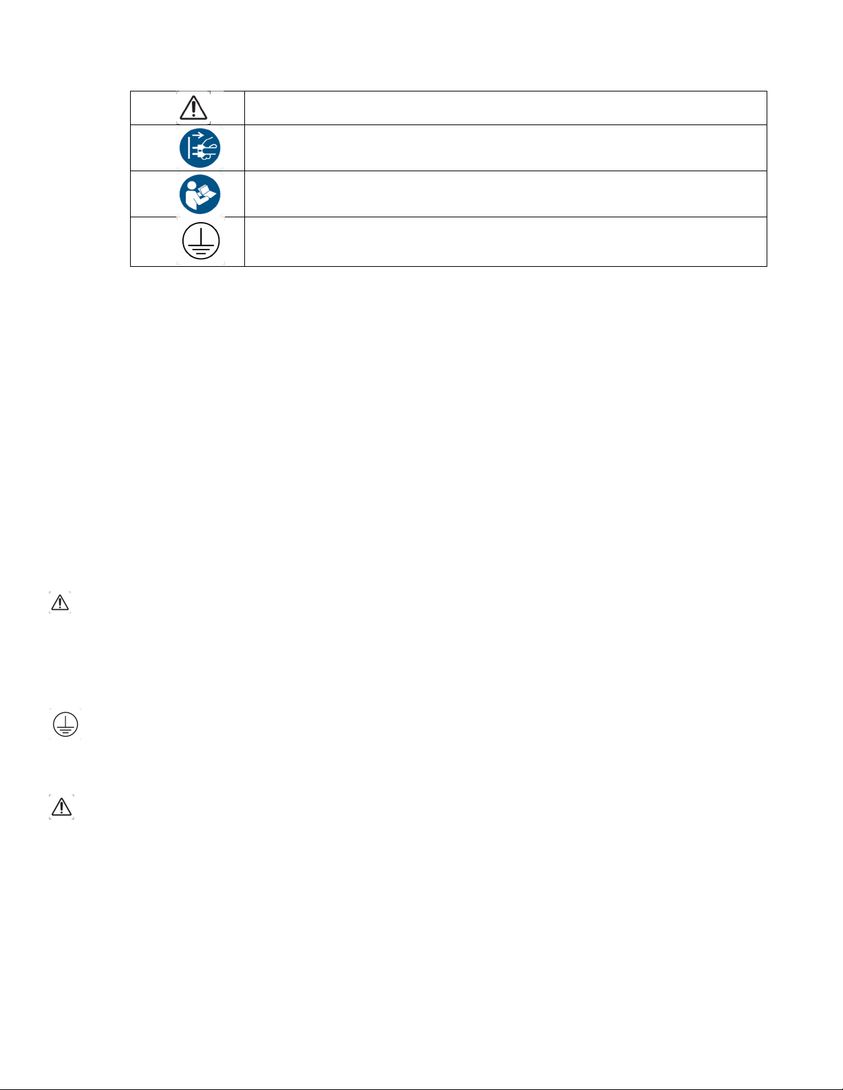
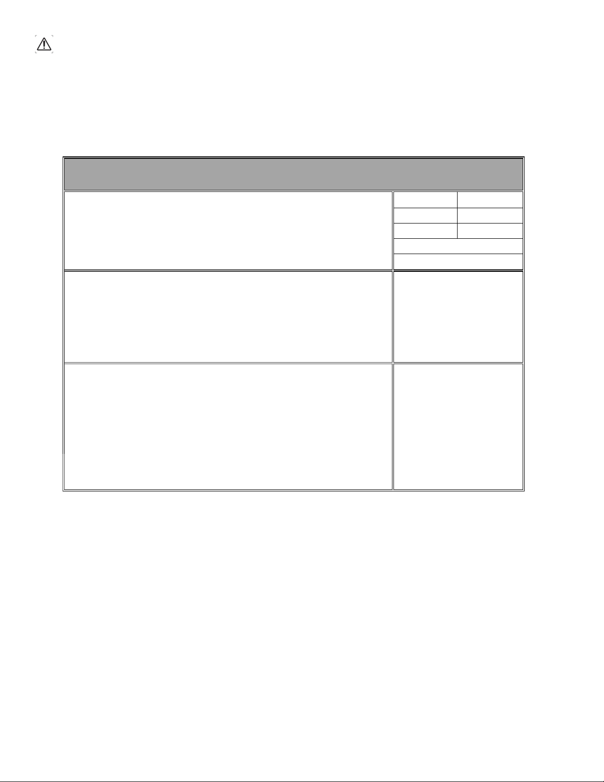
2.5 Symbols
Caution! Warning! Danger!
Always disconnect the plug from the socket before carrying out
any instructions
Please read the instructions carefully before starting the
machine.
Tool uses protective earth and must be plugged into grounded
outlet
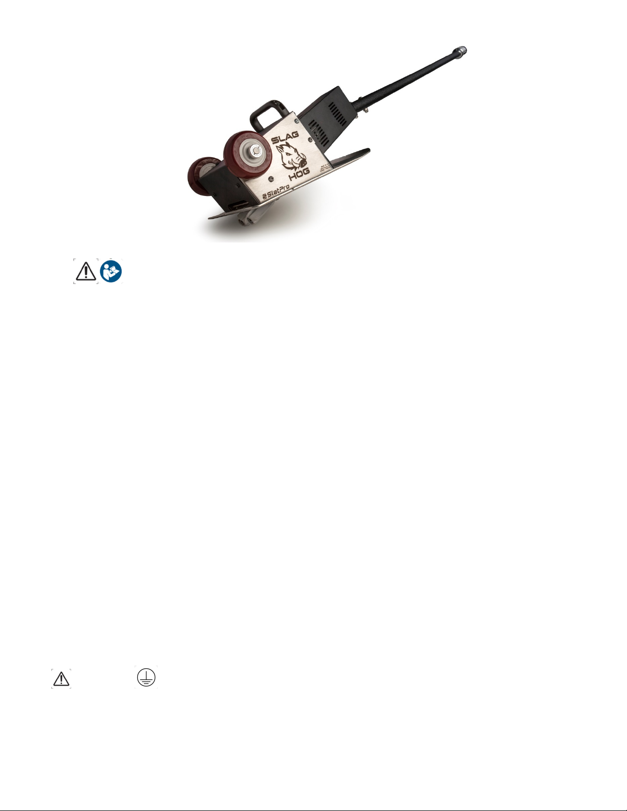
3. Description
The tool is moved along the slats on the bed of a laser machine to remove slag that accumulates while
cutting. Rotary cutting tools ride on each side of the slat to lift and remove the slag. It may be used on
steel, copper or hybrid steel/copper slats. When not in use it may be rolled along the floor and stored in
the upright position.
4. Initial Assembly
The Slag Hog ships in two pieces; power unit and the handle assembly. All fasteners are metric.
Remove the nuts and button head socket screw from the 1.36” diameter stub on the power
unit.
Slide the handle on the stub with the power out cord of the handle on the same side as the
plug in on the power unit.
Plug the power cord from handle tube into the power unit
WARNING
Do not plug into power outlet before verifying the switches on the handle and power unit are
off; both rocker switches to 0.
5. Operation
The tool must be plugged into a receptacle with a grounded outlet
Before plugging into power verify that the two switches are turned off
Wear work gloves and safety glasses when operating
Lift onto the cutting machine bed with care
WARNING Use extreme care near the cutters. Do not touch them unless the tool is unplugged.
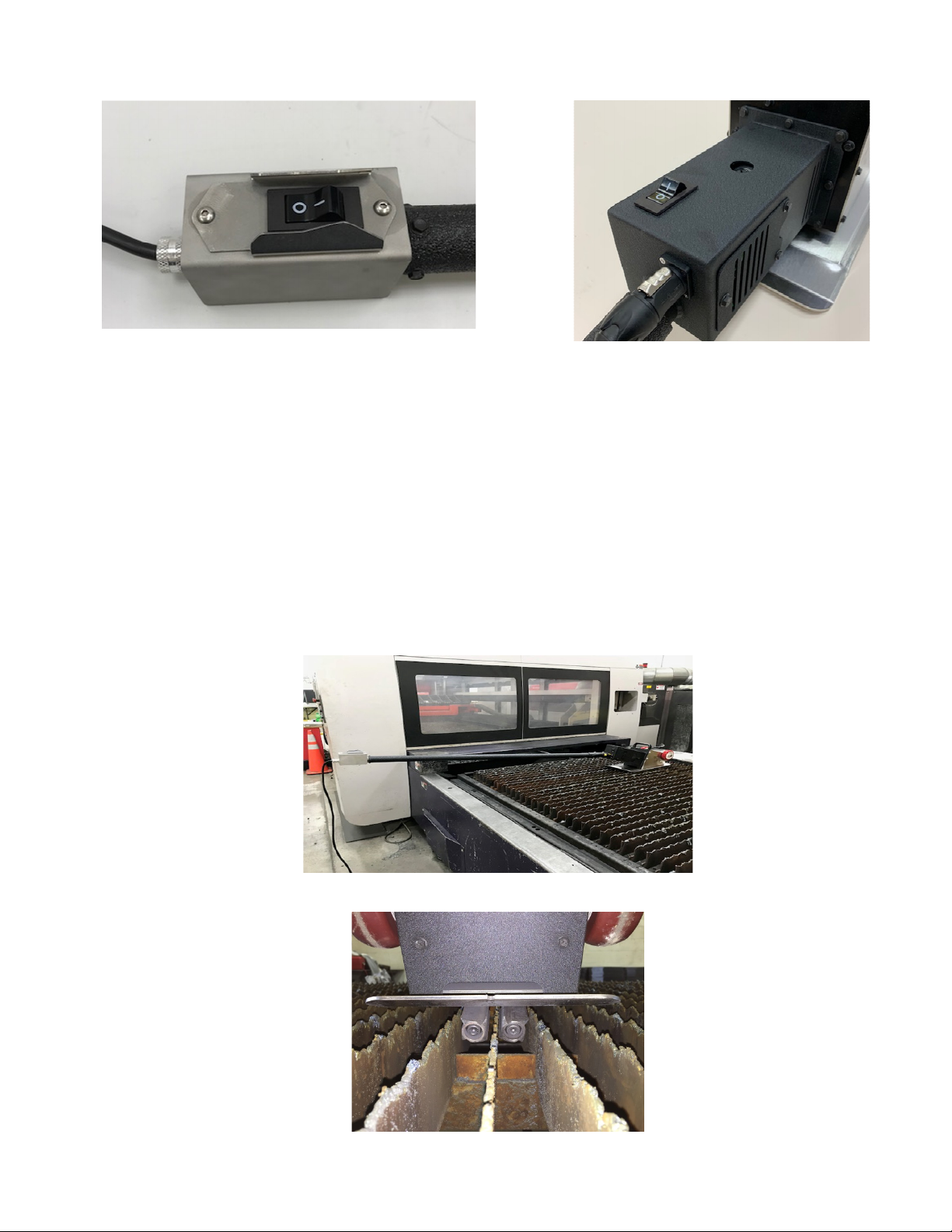
The tool has two on/off switches
Rocker switch on handle end, in off position,
acts as circuit breaker reset in case of over-
current
Rocker Switch on power unit in off position.
Both switches must be in ON or “l” position to run. Turning either switch OFF (“0” position) stops motor
operation.
The upper left picture shows the on/off switch that acts as the circuit breaker when the unit is overworked.
If the slats are not straight it is possible for the cutters to grab onto two slats and stall the motor which will
trip the breaker. If this occurs wait a minute, reset the breaker switch, and resume operation. When slats
have excess slag build up it may cause the circuit breaker to overload. If this happens the operator will
need to reduce force used for cleaning slats. If this occurs, reset the breaker, and resume operation.
To begin use, place the tool on the slat bed of the laser machine, center the cutters over a slat, and turn
on both switches. Cutter rotation will pull the tool down on the slats. The slats can be cleaned by moving
the tool in either direction along the slat.
With switches off, plug tool into a power outlet with appropriate current capacity to accept value given on
machine label or as shown above in the Technical Data table.
Cutters shown centered on slat

To see the unit in operation, go to Youtube and search for Slaghog. The best video is:
https://www.youtube.com/watch?v=PDvEFRREdgg
The cutter geometry is ideal for most slat/pallet bed configurations. If the fit of the cutters on the slats
does not seem correct contact the factory to find out options that are available.
When storing in upright position the unit is unstable and care must be taken to ensure that it does not fall
over, which may lead to damage of handle end components. Damage due to dropping, improper
handling, or falling over is not covered by warranty.

6. Maintenance
WARNING Disconnect power by unplugging from outlet before performing any work on the
tool
6.1 Cutters
The cutters will wear over time and require replacement.
Tools required for replacement
6mm L hex wrench
6mm male hex socket wrench
Adjustable open wrench
Replacement Cutters
66145 SET– 11-12ga Slats
Parts required are RH & LH Cutter Set with SHCS M8xcap screws. Replacement cutters come with
two M8 x 22 cap screws and Blue Loctite 242.
Place the tool on its back with the cutters up.
Place the wrenches as shown and remove the right cutter cap screw with counterclockwise rotation.
Remove the right cutter. The cutter may be tight on the shaft and will require light tapping with a
hammer to remove.

Place adjustable wrench on flats of right shaft and remove left cutter with counterclockwise rotation.
Slide the new right hand and the left-hand cutters so that the flats between the shaft are facing the
base plate as shown. The cutters rotate so that the slag chips are pulled up toward the base plate.
The cutters must be installed as shown.
Apply Loctite 242 to the cap screw threads. With washers in place, thread then tighten cap screws
into shaft ends using the male hex socket wrench and L hex wrench approach.
Flat side of cutters towards base
p
late

6.2 Motor Brushes
If the tool has less torque while in use, it is likely that the brushes need replacement.
Parts Required: Qty 1 of 67179SET Brush Kit for SH3
There are access holes to brushes in top and bottom of Motor Enclosure
Unthread and remove Brush Caps from motor
Remove old brushes and install new and thread caps back in place
6.3 Other maintenance
All other repairs require qualified personnel to perform. In this case, the factory or distributor should
be contacted for further instructions.

SLAGHOG
laser slat cleaner
SLAGHOG WARRANTY
www.slatpro.com
Subject to the exclusions described below, all Slaghog products (“Products”) as manufactured by Slatpro
LLC are warranted to be free from defects in materials and workmanship under normal use and service
for 12 months after the ship date to the purchaser. Unless otherwise set forth in a quotation or agreed to
by Slatpro in writing, Product warranty only applies to the first using purchaser. Warranty is not
transferable beyond the first using purchaser and is limited to new Products sold by Slatpro or through
authorized representatives and channel partners.
EXCLUSIVE REMEDY. In the event that Slatpro determines that a Product contains a defect in materials
or workmanship, then Slatpro, in its sole discretion, will (a) repair the Product, (b) replace the Product with
new or rebuilt (c) refund the purchase price of the Product. THIS LIMITED WARRANTY IS EXCLUSIVE
AND IS IN LIEU OF ALL OTHER EXPRESS AND IMPLIED WARRANTIES, INCLUDING BUT NOT
LIMITED TO THE IMPLIED WARRANTIES OF MERCHANTABILITY AND FITNESS FOR A
PARTICULAR PURPOSE. THE REMEDY OF REPAIR, REPLACEMENT OR REFUND IS BUYER’S
SOLE AND EXCLUSIVE REMEDY UNDER THIS WARRANTY. IN NO EVENT SHALL SLATPRO'S
LIABILITY UNDER THIS WARRANTY EXCEED THE PURCHASE PRICE OF THE PRODUCT GIVING
RISE TO THE WARRANTY CLAIM. All Products which are repaired or replaced shall be warranted only
for the unexpired portion of the original warranty period.
EXCLUSIONS. This warranty does not cover (a) any failures which are not attributable to defects in
materials or workmanship, including without limitation, failures caused by accidents, inadequate
maintenance, misuse, unauthorized modifications or repairs, improper storage, and normal wear and tear,
(b) any consumable parts or accessories, such as cutter blades, are designed to wear over time or through
use of the product, (c) Excessive use which is contributed from overuse, recommended use is for 1
cleaner to service 1-3 machines under normal use conditions. Recommended cleaning interval of
once per week if production levels equal 2 shifts.
WARRANTY RETURNS. No Products shall be returned without prior authorization from Slatpro. Buyer
shall prepay all shipping charges for the return of Products to Slatpro designated service location.
LIMITATION OF LIABILITY. IN NO EVENT SHALL SLATPRO BE LIABLE FOR ANY INCIDENTAL
DAMAGES, CONSEQUENTIAL DAMAGES, SPECIAL DAMAGES, INDIRECT DAMAGES, LOSS OF
PROFITS, LOSS OF REVENUES, OR LOSS OF USE, EVEN IF INFORMED OF THE POSSIBILITY
OF SUCH DAMAGES. SLAPRO'S LIABILITY FOR DAMAGES ARISING OUT OF OR RELATED
TO ANY ORDER IS LIMITED TO THE ORDER PRICE FOR THE SPECIFIC PRODUCT THAT
GIVES RISE TO THE CLAIM. TO THE EXTENT PERMITTED BY APPLICABLE LAW, THESE
LIMITATIONS AND EXCLUSIONS SHALL APPLY REGARDLESS OF WHETHER LIABILITY
ARISES FROM BREACH OF CONTRACT, WARRANTY, TORT (INCLUDING BUT NOT LIMITED TO
NEGLIGENCE), BY OPERATION OR LAW, OR OTHERWISE.
Effective Date: October 15, 2020
Mailing Address: 4757 Mustang Circle
ꞏ
Mounds View, MN 55112 USA Phone: 763-452-4550 www.slatpro.com


Slag Hog Assembly
P/N: 67182-120V or -230V ModelNSH3
Item Qty Part No. Description sheet 1 of 2
The following items are for the drive portion of the assembly
11 67121 Input Shaft
2 2 66143 Cutter Shaft
3 2 66135 Idler Shaft
4 1 67077 Driven Idler Shaft
5 2 66140 Gear Support Plate Cutter Side
6 2 66141 Gear Support Plate Motor Side
7 2 66139 Cutter Support Plate
8 9 66115 Needle Bearing .62 ID
9 4 67007 Needle Bearing .62 ID Closed End
10 4 67005 Needle Bearing .5 ID
11 2 67006 Needle Bearing .38 ID
12 1 67167 Ball Bearing .62IDx1.38ODx.344W
13 1 67168 Seal .62IDx1.12ODx,12W
14 2 NI Clamp Collar 9520T8
15 4 67058 Input Shaft Spacer
16 4 66081 Idler Shaft Washer
17 2 66137 Shaft Washer (.5 ID)
18 2 66138 Shaft Washer (.38 ID)
19 4 66054 Pivot Washer
20 2 66048 Spur Gear 14T
21 2 66049 Spur Gear 16T
22 2 66144 Spur Gear 11T
23 1 66142 Gear Box NSH
24 1 66042 Pivot End Plate Cutter Side
25 1 67119 Gear Housing
26 1 66044-RH Top Gear Support RH
27 1 66044-LH Top Gear Support LH
28 2 66025 Spring Guide Male
29 2 66051 Spring Guide Female
30 2 66126 Die Spring
31 6 NI Thrust Washer .62ID 5906K516
32 4 NI Needle Brg Thrust Washer .38 ID 5909K251
33 2 NI Needle Thrust Bearing .38 ID 5909K25
34 5 NI Machine Key 98870A140
35 2 NI Dowel Pin, Pull-out 97175A390
36 2 NI Clamp Collar 8mm ID 3369K14
37 1 66039 Chip Deflector
38 2 66136 Spacer, Cutter
39 2 66145 SET Cutter Set

Slag Hog Assembly
P/N: 67182 ModelNSH3
Item Qty Part No. Description sheet 2 of 2
The following items are for the housing portion of the assembly
50 1 67114 Side Plate Set
51 1 67164 Base Plate
52 1 67120 Motor Mount Plate
53 1NIOring -047 9452K312
54 1 67118 Motor -120V or -230V
55 1 67155 Gear 93T
56 1 67156 Gear Shaft 20T
57 1 67157 Gear 82T
58 1 67159 Filler Gear Housing
59 267166 Bearing 10 IDx26 ODx8mm W
60 1 67112 Motor Enclosure
61 1 67116 Top Cover
62 1 67115 Wire Access Cover
63 2 66117 Wheel
64 2 NI Clamp Collar 6157K14
65 1 NI Shaft .5 dia x 10.38 1255T17
66 1 66116 Handle
67 1 67063 On/Off Switch 15A
68 1 67065 Receptacle
69 1 NI Ground Wire 2196k42
70 REF 67179 Carbon Brush Set for Motor
The following items are for the fasteners
80 2 NI Flat Hd Phillips Mach Scr M3x8 92010A118
81 8 NI Socket Head Cap Screw M4x14 91290A150
82 21 NI Vib Resist Hex Hd Flange M5x12 92820A215
83 6 NI Hex Hd Flange M5x25 98093A212
84 4 NI Socket Head Cap Screw M5x14 91290A230
85 3 NI Button Hd SCS M6x12 91239A318
86 2 NI Socket Head Cap Screw M6x25 90128A265
87 4 NI Button-Head SCS M8x16 91306A677
88 14 NI SHCS M8x25 90128A275
89 9 NI Nylock Flanged Nut M6x1 99908A101
90 2 NI Nylock Nut M10x1.5 90576A118
91 2 NI Button Hd SCS M10x55 SST 92095A426
92 2 NI SHCS M8x22 91290A428
95 1 67171 Foam Packaging SH3
See67173forhandletubeoptions
NImeansnon‐inventoryitem
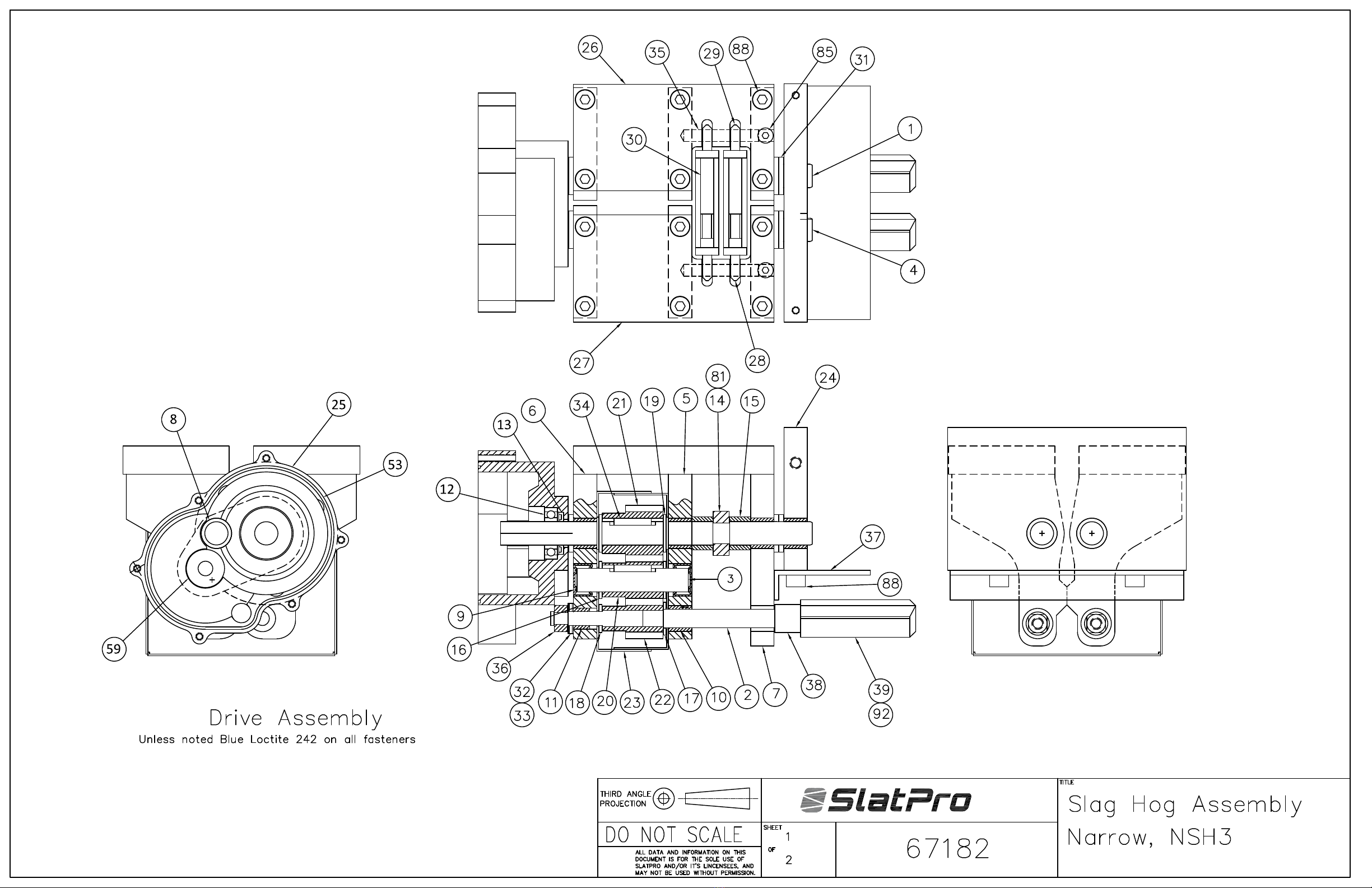
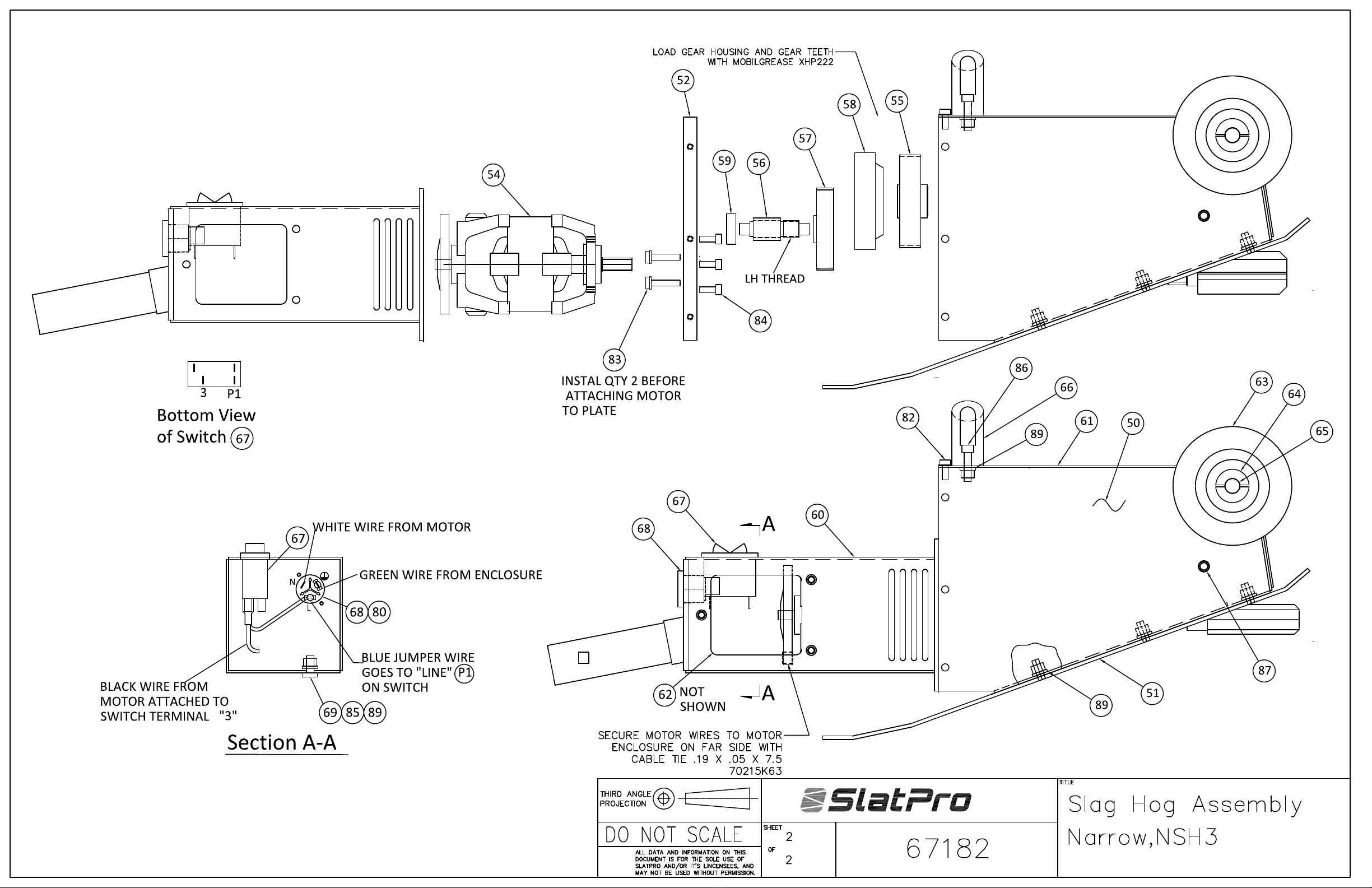

Table of contents
Other SlatPro Tools manuals


