Fröling Screening screw 150 User manual

Installation and Operating Instructions
Screening screw 150
Translation of the original German operating and installation instructions for technicians and operators
Read and follow the instructions and safety information!
Technical changes, typographical errors and omissions reserved!
M1940017_en | Edition 03/04/2017
Fröling GesmbH | A-4710 Grieskirchen, Industriestraße 12 | www.froeling.com

Table of Contents
1 General 4
1.1 Functional description 5
2 Safety 6
2.1 Hazard levels of warnings 6
2.2 Permitted uses 7
2.2.1 Permitted fuels 8
Wood chips
8
2.3 Qualification of staff 8
2.3.1 Qualification of assembly staff 8
2.3.2 Personal protective equipment for assembly staff 9
2.3.3 Qualification of operating staff 9
2.3.4 Protective equipment for operating staff 9
2.4 Design information 10
2.4.1 Standards 10
2.4.2 Requirements at the installation site 10
2.5 Safety devices 11
2.6 Residual risks 11
3 Technical information 13
3.1 Dimensions 13
3.2 Technical data 14
4 Assembly 15
4.1 Weight 15
4.2 Fitting the troughs 16
4.3 Fitting the top part of gravity shaft and drive unit 18
4.4 Fitting attachments 20
4.5 Fitting adjustable feet in boiler room (optional) 20
4.6 Closing the wall penetration 21
4.7 Receiving tank for dust / fines 21
4.8 Adjusting the screen 22
4.9 Connecting the system 23
4.9.1 Electrical connection 23
4.9.2 Connecting the sprinkler system 23
5 Operating the system 24
5.1 Initial startup 24
5.2 During operation 24
5.3 Decommissioning 25
5.3.1 Disassembly 25
5.3.2 Disposal 25
6 Servicing 26
Table of Contents
2 Fröling GesmbH | A-4710 Grieskirchen, Industriestraße 12 | www.froeling.com

1 General
Thank you for choosing a quality product from Froling. The product features a state-of-
the-art design and conforms to all currently applicable standards and testing
guidelines.
Please read and observe the documentation provided and always keep it close to the
system for reference. Observing the requirements and safety information in the
documentation makes a significant contribution to safe, appropriate, environmentally
friendly and economical operation of the system.
The constant further development of our products means that there may be minor
differences from the pictures and content. If you discover any errors, please let us
know: [email protected].
Subject to technical change.
This is an incomplete machine as defined by the Machinery Directive. The incomplete
machine must only be started up when it has been confirmed that the machine, in
which the incomplete machine has been installed, conforms to the provisions of
Directive 2006/42/EC.
Compliance with the open provisions and verification of the correct installation must be
confirmed in the delivery certificate of the declaration of installation (included in
documentation).
Issuing a delivery
certificate
1General
4 Fröling GesmbH | A-4710 Grieskirchen, Industriestraße 12 | www.froeling.com

1.1 Functional description
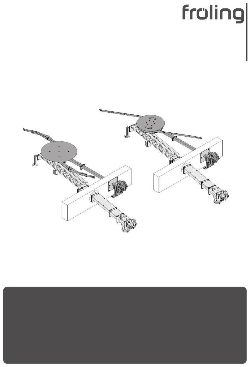
Froling’s “Screening Screw 150” discharge system consists of:
1 Top part of discharge gravity shaft (e.g. FBR, TGR, feed screw etc.)
2 Transfer beaker
3 Inspection cover
4 Chain drive for screening screw
5 Light barrier to monitor fill level
6 Bottom part of gravity shaft
7 Ejection pipe for dust / fines
8 Closed trough with screen
9 Closed trough
10 Gravity shaft cover with safety limit switch
11 Drive of feed screw
12 System fuel lock / stoker
Using a screening screw can compensate for long distances between the discharge
and the system, with some of the fine wood chips being filtered out by an adjustable
screen.
If fuel is requested via the system controller, the discharge starts feeding the wood
chips to the feed screw. This feeds the material via the closed trough to the transfer
position, where it falls through to another feed screw or through the system’s burn
back protection system (burn back flap, rotary valve or fuel lock).
General 1
Functional description
Installation and Operating Instructions Screening screw 150 | M1940017_en 5

2 Safety
2.1 Hazard levels of warnings
This documentation uses warnings with the following hazard levels to indicate direct
hazards and important safety instructions:
DANGER
The dangerous situation is imminent and if measures are not observed it will lead
to serious injury or death. You must follow the instructions!
WARNING
The dangerous situation may occur and if measures are not observed it will lead
to serious injury or death. Work with extreme care.
CAUTION
The dangerous situation may occur and if measures are not observed it will lead
to minor injuries or damage to property.
2Safety
Hazard levels of warnings
6 Fröling GesmbH | A-4710 Grieskirchen, Industriestraße 12 | www.froeling.com

2.2 Permitted uses
Froling’s “Screening screw 150“ discharge system is only designed to discharge fuels
from suitable stores. Only use fuels specified in the “Permitted fuels” section.
Depending on the material fed, the screening screw filters out some of the fine wood
chips, but is no replacement for a filtration system!
The unit should only be operated when it is in full working order. It must be operated in
accordance with the instructions, observing safety precautions, and you should ensure
you are aware of the potential hazards. The inspection and cleaning intervals in the
operating instructions must be observed. Ensure that any faults which might impair
safety are rectified immediately.
The manufacturer or supplier is not liable for any damage resulting from non-permitted
uses.
Only original spare parts or specific alternative spare parts authorised by the
manufacturer may be used. Any kind of change or modification made to the product
will invalidate the manufacturer’s conformity with the applicable guideline(s). In such
cases, the product will need to undergo new hazard evaluation procedures by the
operator. The operator will then be fully responsible for the declaration of conformity
according to the valid guideline(s) for the product and will need to issue a
corresponding declaration for the device. This person will then assume all of the rights
and responsibilities of a manufacturer.
DANGER
If the device is used incorrectly:
Incorrect use of the system can cause severe injury and damage.
When operating the system:
❒ Observe the instructions and information in the manuals
❒ Observe the details on procedures for operation, maintenance and cleaning,
as well as troubleshooting in the respective manuals.
❒ Any work above and beyond this (e.g. servicing) must be carried out by a
heating engineer approved by Fröling Heizkessel- und Behälterbau GesmbH
or by Froling customer services
Safety 2
Permitted uses
Installation and Operating Instructions Screening screw 150 | M1940017_en 7
2.2.1 Permitted fuels
Wood chips
Criterion Designation as per Description acc. to
ÖNORM M 7133
ÖNORM M 7133 EN ISO 17225
Water content W10 M10 dried in chamber
W20 M20 air-dried
W30 M30 suitable for storage
W35 M35 limited suitability for
storage
Size G30 P16S Fine wood chip
G50 P31S Medium-sized wood
chip
EU: Fuel as per EN ISO 17225 – Part 4: Wood chips class A1 / P16S-P31S
Additional for
Germany:
Fuel class 4 (§3 of the First Federal Emissions Protection Ordinance
(BimSchV) - applicable version)
2.3 Qualification of staff
2.3.1 Qualification of assembly staff
CAUTION
Assembly and installation by unqualified persons:
Risk of personal injury and damage to property
During assembly and installation:
❒ Observe the instructions and information in the manuals
❒ Only allow appropriately qualified personnel to work on the system
Assembly, installation, initial startup and servicing must always be carried out by
qualified personnel:
- Heating technician / building technician
- Electrical installation technician
- Froling customer services
The assembly staff must have read and understood the instructions in the
documentation.
Note on standards
2Safety
Permitted uses
8 Fröling GesmbH | A-4710 Grieskirchen, Industriestraße 12 | www.froeling.com

2.3.2 Personal protective equipment for assembly staff
You must ensure that staff have the protective equipment specified by accident
prevention regulations.
▪ For transportation, setup and assembly:
- suitable work wear
- protective gloves
- sturdy shoes (min. protection class S1P)
2.3.3 Qualification of operating staff
CAUTION
If unauthorised persons enter the store:
Risk of personal injury and damage to property
❒ The operator is responsible for keeping unauthorised persons, in particular
children, away from the system.
Only trained operators are permitted to operate the unit. The operator must also have
read and understood the instructions in the documentation.
2.3.4 Protective equipment for operating staff
You must ensure that staff have the protective equipment specified by accident
prevention regulations.
▪ For operation, inspection and cleaning:
- suitable work wear
- protective gloves
- sturdy shoes
Safety 2
Qualification of staff
Installation and Operating Instructions Screening screw 150 | M1940017_en 9

2.4 Design information
Carrying out modifications to the system and changing or disabling safety equipment
is prohibited.
Always comply with all fire, building and electrical regulations when installing and
operating the system, in addition to following the assembly and operating instructions
and mandatory regulations that apply in the country of use.
2.4.1 Standards
The system must be installed and commissioned in accordance with the local fire and
building regulations. The following standards and regulations should be observed in
any case:
ÖNORM / DIN EN 60204 Safety of machines; Electrical equipment of machines, Part 1:
General requirements
TRVB H 118 Technical directives for fire protection/prevention (Austria)
ÖNORM H 5170 Construction and fire protection requirements (Austria)
ÖNORM H 5190 Heating systems - Acoustic insulation
EN ISO 13857 Safety of machines; Safety distances for maintaining a safe
distance from hazardous areas
2.4.2 Requirements at the installation site
▪ The floor must be even, clean and dry and have an adequate load-bearing
capacity
▪ Always install control cabinet indoors
▪ If installing outdoors, protect electrical components (e.g. geared motors) from the
effects of weather
▪ Covers provided by the customer must be designed in such a way that
maintenance areas remain freely accessible
▪ Low temperatures in conjunction with wet wood chips can cause system
components to freeze. Protect the system from frost!
▪ Protective structures must be designed in accordance with the applicable
standards and regulations
2Safety
Design information
10 Fröling GesmbH | A-4710 Grieskirchen, Industriestraße 12 | www.froeling.com

2.5 Safety devices
Safety equipment Safety function
Limit switch for top of gravity
shaft:
Protection against access to the danger area of the feed/
discharge screw when the system is switched on
❒ If the inspection cover is opened, the system is switched
off via the limit switch
➥The power supply remains switched on
Water Sprinkler System: Self-activating extinguisher system to limit burn back around
the top of the gravity shaft.
If the temperature in the top of the gravity shaft rises above
95°C, the valve of the sprinkler system opens, water flows out
and prevents the fire from spreading to the fuel store.
2.6 Residual risks
The discharge system has been designed and built to comply with the relevant safety
directives. Nevertheless by the nature of its operation and function, there are residual
risks which cannot be eliminated completely.
DANGER
When working on the unit with a live power supply:
Serious injury possible due to automatic startup!
When working on the system or in the store, it is essential that the five safety
directives are followed:
❒ Disconnect all poles on all sides
❒ Secure so that it cannot be switched on again
❒ Check that there is no power
❒ Earth and short circuit
❒ Cover any adjacent live parts and limit area of risk
Safety 2
Safety devices
Installation and Operating Instructions Screening screw 150 | M1940017_en 11

CAUTION
If unauthorised fuel types are used:
Non-standard fuels can cause stiffness and block the system, resulting in the
failure/breakage of components.
Therefore:
❒ Only use fuels specified in the "Permitted uses" section of these operating
instructions.
2Safety
Residual risks
12 Fröling GesmbH | A-4710 Grieskirchen, Industriestraße 12 | www.froeling.com

3 Technical information
3.1 Dimensions
H5
B1
B2
D4
H5
B1
B2
D4
D5
H4
H1
H2
L2
L1 L3 L4 L5 L6
D2
α
D3
A
A
B
B
Schnitt A-A Schnitt B-B
H3
D1
Item Description Unit Value
L1 Length, chain guard mm 156
L2 Length, bottom part of gravity shaft 500
L3 Length, screening screw 2000
L4 Length, closed trough see installation diagram
L5 Length, top part of gravity shaft 405
L6 Length, drive 215
H1 Height, bottom part of gravity shaft see installation diagram
H2 Height, transfer beaker 60
H3 Height, top part of gravity shaft connection see installation diagram
H4 Height, screening screw trough 336
H5 Height, closed trough 206
D1 Diameter, ball connection 180
D2 Diameter, ejection pipe for dust / fines 100
D3 Diameter, ball connection 180
D4 Diameter, feed screw 150
D5 Diameter, screening screw 50
B1 Width, trough cover 280
W2 Width, trough 200
αInclination ° 5 (±8)
Technical information 3
Dimensions
Installation and Operating Instructions Screening screw 150 | M1940017_en 13

3.2 Technical data
Screening screw 150
Geared motor Offset gears
Electrical output 0.55 kW
Speed 10.9 rpm
Weight 28.5 kg
Electricity supply 400 VAC / 50 Hz
Safety limit switch 24 VDC
3Technical information
Technical data
14 Fröling GesmbH | A-4710 Grieskirchen, Industriestraße 12 | www.froeling.com

4 Assembly
NOTICE! If several feed screws are being used, it is recommended that the screening
screw be mounted closest to the system. This means that the dust generated from the
feed can also be filtered out.
4.1 Weight
The total weight will depend on the design of the screening screw. This must be taken
into account for transportation and assembly.
Item Description Weight [kg]
1Transfer beaker Ø 180 4.0
2Bottom part of gravity shaft 0° with support and chain
guard
36.0
3Screening screw trough 78.0
4Closed trough (specified in kg/m) 26.5
5Top part of gravity shaft 5° 19.5
6Screw drive ⇨ See "Technical
data" [page 14]
7Feed screw Ø 150 (specified in kg/m) 12.5
8Screening screw Ø 50 9.5
Assembly 4
Weight
Installation and Operating Instructions Screening screw 150 | M1940017_en 15

4.2 Fitting the troughs
NOTICE! The number of closed troughs (D) depends on the total length of the
screening screw
❒ Secure bottom part of gravity shaft (A) with ceramic fibre seal (B) to the screening
screw trough (C) (opposite inspection cover)
- 4 hexagonal screws M12x35
- 4 hexagonal nuts M12
- 4 spacer washers M12
❒ Connect all closed troughs (D) to each other
➥For each flange connection
- 1 ceramic fibre seal (B)
- 4 hexagonal screws M12x35
- 4 hexagonal nuts M12
- 4 spacer washers M12
❒ Remove cover plate (A) from screening screw trough
❒ Push in screening screw (B) as shown and refit the cover plate (A)
❒ Push flange bearing unit (C) onto shaft stub of screening screw (B) and fix in place
4Assembly
Fitting the troughs
16 Fröling GesmbH | A-4710 Grieskirchen, Industriestraße 12 | www.froeling.com

❒ Push feed screw (A) onto bottom part of gravity shaft
❒ Secure bearing bracket (B) to bottom part of gravity shaft with ceramic fibre seal
(C)
➥Shaft stubs of feed and screening screws must protrude out of flange bearing
units
❒ Insert two circlips (A) into shaft grooves of screening screw
❒ Insert keys (B) into grooves on shaft stub
❒ Secure chain wheels (C, D) with washers onto shaft stubs
❒ Place roller chain around sprockets of the two screws and secure with chain lock
❒ Fit chain tensioner (A) to bearing bracket and tighten chain
❒ Set the sprocket on the chain tensioner (A) so that all three sprockets are flush
Assembly 4
Fitting the troughs
Installation and Operating Instructions Screening screw 150 | M1940017_en 17

❒ Fit chain guard (A) to bearing bracket from underneath and secure with captive
screw (B)
For ball design:
❒ Secure transfer beaker (C) to round flange of bottom part of gravity shaft with
ceramic fibre seal (D)
4.3 Fitting the top part of gravity shaft and drive unit
❒ Secure top part of gravity shaft (A) with seal (B) to the closed trough
- 4 hexagonal screws M12x35
- 4 hexagonal nuts M12
- 4 spacer washers M12
❒ Secure flange plate (C) with seal (D) to upper part of gravity shaft
- 4 hexagonal screws M12x35
- 4 hexagonal nuts M12
- 4 spacer washers M12
4Assembly
Fitting the top part of gravity shaft and drive unit
18 Fröling GesmbH | A-4710 Grieskirchen, Industriestraße 12 | www.froeling.com

❒ Push the flange bearing (A) onto the screw end and secure to upper part of gravity
shaft
- 4 hexagonal screws M12x25
❒ Push the space ring (B) onto the screw end
❒ Insert key (C) into nut on screw end
❒ Secure torque support with pin (D) to top part of gravity shaft
- 2 hexagonal screws M10x20
➥Centre distance of pin and screw end: 150 mm
❒ Secure torque support with bearing (A) to the geared motor as illustrated
- 8 hexagonal screws M8x20
❒ Push the geared motor (B) onto the screw end
❒ Secure locking washer (C) with hexagonal screw and washer
- 1 hexagonal screw M10x25
If the geared motor cannot be installed as shown above for reasons of space, it is
possible to turn the drive unit:
❒ Turn the torque support with bearing 180° and secure to geared motor
❒ Turn the geared motor and torque support 180° and fit to the screw end and
torque support as explained above
Assembly 4
Fitting the top part of gravity shaft and drive unit
Installation and Operating Instructions Screening screw 150 | M1940017_en 19

4.4 Fitting attachments
❒ Secure limit switch (A) to upper part of gravity shaft
- 2 cylinder head screws M5x40
➥The reel of the safety limit switch (A) must be positioned as illustrated
❒ Fit the elbow (B) of the water sprinkler system to the upper sleeve on the upper
part of gravity shaft
❒ Fit the immersion sleeve (C) of the water sprinkler system to the side sleeve
Prepare the geared motor:
❒ Remove the transport lock
❒ Fit the vent screw (supplied) to the highest point
4.5 Fitting adjustable feet in boiler room (optional)
If the closed duct in the boiler room exceeds 2m, an additional support is
recommended:
Ø 15 mm
❒ Remove the brackets from the supporting post
❒ Remove the screws of the trough flange at the relevant position
❒ Secure the brackets to the trough flange with the previously removed screws
❒ Position the supporting post at the bracket and screw together
Screwing the adjustable feet to the floor:
❒ Make two holes each in the floor on the left and right for the adjustable feet
4Assembly
Fitting attachments
20 Fröling GesmbH | A-4710 Grieskirchen, Industriestraße 12 | www.froeling.com
This manual suits for next models
4
Table of contents
Other Fröling Industrial Equipment manuals

Fröling
Fröling FBR-G2 User manual

Fröling
Fröling BFSU User manual

Fröling
Fröling TM 320 User manual

Fröling
Fröling Turbomat 320 User manual

Fröling
Fröling BFSV User manual

Fröling
Fröling T4e User manual

Fröling
Fröling BFSV-H User manual

Fröling
Fröling FBR-G User manual

Fröling
Fröling GAR 110 User manual

Fröling
Fröling 250 User manual
Popular Industrial Equipment manuals by other brands

Schenker
Schenker MODULAR 30 Electron Operation and maintenance manual

Datalogic
Datalogic STS400 installation manual

Mayr
Mayr ROBA-ES 940 Series Installation and operational instructions

Becca
Becca SOLVENT SAVER Operator's guide

Sit
Sit 845 Sigma Use and Installation Instructions

Jorc
Jorc 34000 Maintenance instructions