HOW TO USE THIS PUBLICATION
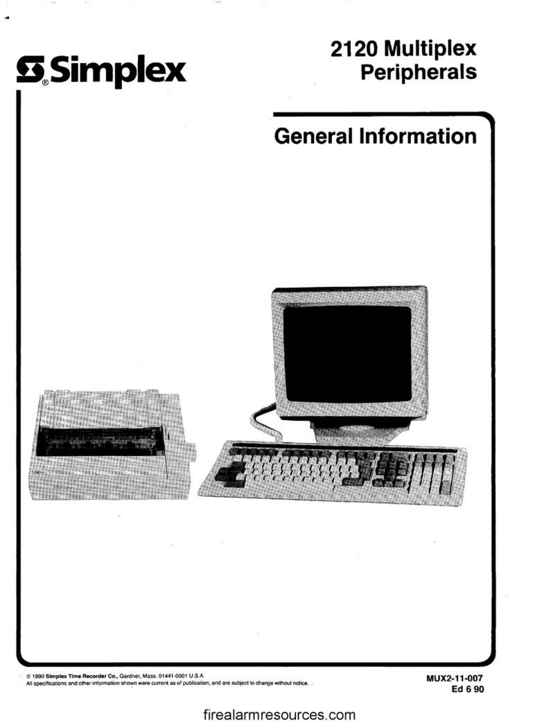
This publication provides information on 2120 Multiplex dual channel voice communications systems. Typical
equipment configurations are illustrated, as are specific interconnections between 2120 and 2001 equipment.
This manual is divided into the following sections:
l
MAIN EQUIPMENT
l
REMOTE EQUIPMENT
l
CLASS A AUDIO FOR DUAL CHANNEL SYSTEMS
For More Detailed lnformation . . .
refer to the documents listed below.
2001 Voice Communications Wiring Diagrams
2001 Systems Troubleshooting Guide
2001 Voice Communications Module Descriptions
System interconnection drawings for the specific installation
Equipment cabinet drawings for the specific installation
INTRODUCTION
2120 Multiplex dual channel voice communications systems are similar to single channel systems. Both use 2001
voice communications equipment to provide their basic functions. However, a dual channel voice system has an
advantage over a single channel system: The dual channel system can transmit two different audio messages
to separate areas of a building at the same time. Simultaneous operation requires some special features:
l
A set of SMPL programs that appropriately operate system speaker circuits.
l
Two audio control modules.
l
Two riser power preamps.
l
Two audio risers.
AND
l
(In certain applications) Special FABT or ET dual channel audio relay boards.
There are two basic configurations for 2120 dual channel audio systems (Figures 1A and 1B). The difference
between the two is the size of the SCC used. Figure 1A illustrates a system in which a lo-module SCC is used;
in this application, the two riser power preamps are located in the SCC cabinet (along with the microphone
enclosure assembly, if used).
