steute Ex STM 298 3G/D Series Programming manual

Montage- und Anschlussanleitung / Sicherheitszuhaltung
Mounting and wiring instructions / Solenoid interlock
Instructions de montage et de câblage / Interverrouillage de sécurité
//
Ex STM 298 ... -3G/D
steute Technologies GmbH & Co. KG
Brückenstraße 91, 32584 Löhne, Germany, www.steute.com
1 / 24
Bestimmungsgemäßer Gebrauch
Sicherheitsschalter der Baureihe Ex STM 298 ... -3G/D sind Verriege-
lungseinrichtungen mit Zuhaltung (Bauart2). Der Betätiger besitzt
eine geringe Codierungsstufe. In Verbindung mit einer beweglichen
trennenden Schutzeinrichtung und der Maschinensteuerung verhin-
dert dieses Sicherheitsbauteil, dass die Schutzeinrichtung geöffnet
werden kann, solange eine gefährliche Maschinenfunktion ausge-
führt wird.
Das bedeutet:
- Einschaltbefehle, die eine gefährliche Maschinenfunktion hervor-
rufen, dürfen erst dann wirksam werden, wenn die Schutzeinrich-
tung geschlossen und zugehalten ist.
- Die Zuhaltung darf erst dann entsperrt werden, wenn die gefährli-
che Maschinenfunktion beendet ist.
- Das Schließen und Zuhalten einer Schutzeinrichtung darf kein
selbstständiges Anlaufen einer gefährlichen Maschinenfunktion
hervorrufen. Hierzu muss ein separater Startbefehl erfolgen. Aus-
nahmen hierzu siehe ENISO12100 oder relevante C-Normen.
Geräte dieser Baureihe eignen sich auch für den Prozessschutz.
Vor dem Einsatz des Geräts ist eine Risikobeurteilung an der Maschi-
ne durchzuführen z.B. nach folgenden Normen:
- ENISO13849-1, Sicherheitsbezogene Teile von Steuerungen
- ENISO12100, Sicherheit von Maschinen - Allgemeine Gestaltungs-
leitsätze - Risikobeurteilung und Risikominderung
- IEC62061, Sicherheit von Maschinen – Funktionale Sicherheit si-
cherheitsbezogener elektrischer, elektronischer und program-
mierbarer elektronischer Steuerungssysteme
Zum bestimmungsgemäßen Gebrauch gehört das Einhalten der ein-
schlägigen Anforderungen für den Einbau und Betrieb, insbesondere
nach folgenden Normen:
- ENISO13849-1, Sicherheitsbezogene Teile von Steuerungen
- ENISO14119, Verriegelungseinrichtungen in Verbindung mit tren-
nenden Schutzeinrichtungen
- EN60204-1, Elektrische Ausrüstung von Maschinen
- DINEN1127-1 Explosionsfähige Atmosphären – Explosionsschutz
– Teil 1: Grundlagen und Methodik
- EN60079-0, Explosionsfähige Atmosphäre,
Geräte - Allgemeine Anforderungen
- EN60079-15, Explosionsfähige Atmosphäre,
Teil 15: Geräteschutz durch Zündschutzart „n“
- EN60079-31, Explosionsfähige Atmosphäre,
Teil 31: Geräte - Staubexplosionsschutz durch Gehäuse „tc“
- EN1127-1, Explosionsfähige Atmosphären - Explosionsschutz
Wichtig!
- Der Anwender trägt die Verantwortung für die
korrekte Einbindung des Geräts in ein sicheres
Gesamtsystem. Dazu muss das Gesamtsystem
z.B. nach ENISO13849-2 validiert werden.
- Wird zur Bestimmung des Perfomance Le-
vels (PL) das vereinfachte Verfahren nach
ENISO13849-1:2015, Abschnitt 6.3 benutzt, redu-
ziert sich möglicherweise der PL, wenn mehrere
Geräte hintereinander geschaltet werden.
- Eine logische Reihenschaltung sicherer Kon-
takte ist unter Umständen bis zu PLd möglich.
Nähere Informationen hierzu gibt ISOTR24119.
- Liegt dem Produkt ein Datenblatt bei, gelten die
Angaben des Datenblatts, falls diese von der Be-
triebsanleitung abweichen.
Sicherheitshinweise
=WARNUNG
Lebensgefahr durch unsachgemäßen Einbau oder
Umgehen (Manipulation). Sicherheitsbauteile er-
füllen eine Personenschutz-Funktion.
- Sicherheitsbauteile dürfen nicht überbrückt,
weggedreht, entfernt oder auf andere Wei-
se unwirksam gemacht werden. Beachten Sie
hierzu insbesondere die Maßnahmen zur Ver-
ringerung der Umgehungsmöglichkeiten nach
ENISO14119:2013, Abschn. 7.
- Der Schaltvorgang darf nur durch speziell dafür
vorgesehene Betätiger ausgelöst werden.
- Stellen Sie sicher, dass kein Umgehen durch Er-
satzbetätiger stattfindet. Beschränken Sie hier-
zu den Zugang zu Betätigern und z.B. Schlüs-
seln für Entriegelungen.
- Montage, elektrischer Anschluss und Inbetrieb-
nahme ausschließlich durch autorisiertes Fach-
personal, welches über spezielle Kenntnisse im
Umgang mit Sicherheitsbauteilen verfügt.
=VORSICHT
Gefahr durch hohe Gehäusetemperatur bei Umge-
bungstemperaturen größer 40°C.
- Schalter gegen Berühren durch Personen oder
brennbarem Material schützen.
Funktion
Der Sicherheitsschalter ermöglicht das Zuhalten von beweglichen
trennenden Schutzeinrichtungen.
Im Schalterkopf befindet sich eine drehbare Schaltwalze, die durch
den Zuhaltebolzen blockiert/freigegeben wird.
Beim Einführen/Herausziehen des Betätigers und beim Aktivieren/
Entsperren der Zuhaltung wird der Zuhaltebolzen bewegt. Dabei
werden die Schaltkontakte betätigt.
Deutsch (Originalbetriebsanleitung)

Montage- und Anschlussanleitung / Sicherheitszuhaltung
Mounting and wiring instructions / Solenoid interlock
Instructions de montage et de câblage / Interverrouillage de sécurité
//
Ex STM 298 ... -3G/D
steute Technologies GmbH & Co. KG
Brückenstraße 91, 32584 Löhne, Germany, www.steute.com
2 / 24
Bei blockierter Schaltwalze (Zuhaltung aktiv) kann der Betätiger
nicht aus dem Schalterkopf gezogen werden. Konstruktionsbedingt
kann die Zuhaltung nur aktiviert werden, wenn die Schutzeinrichtung
geschlossen ist (Fehlschließsicherung).
Die Konstruktion des Sicherheitsschalters ist so ausgeführt, dass
Fehlerausschlüsse auf interne Fehler gemäß ENISO13849-2:2013,
TabelleA4, angenommen werden können.
Zuhaltungsüberwachung
Alle Ausführungen verfügen über mindestens einen sicheren Kon-
takt für die Überwachung der Zuhaltung. Beim Entsperren der Zu-
haltung werden die Kontakte Ægeöffnet.
Türmeldekontakt
Die Ausführungen R und A verfügen zusätzlich über mindestens ei-
nen Türmeldekontakt. Je nach Schaltelement können die Türmel-
dekontakte zwangsöffnend (Kontakte A) oder nicht zwangsöffnend
sein.
Beim Öffnen der Schutzeinrichtung werden die Türmeldekontakte
betätigt.
Ausführung R
(Zuhaltung durch Federkraft betätigt und durch Energie EIN ent-
sperrt)
- Zuhaltung aktivieren: Schutzeinrichtung schließen, keine Span-
nung am Magnet
- Zuhaltung entsperren: Spannung an Magnet anlegen
Die durch Federkraft betätigte Zuhaltung arbeitet nach dem Ruhe-
stromprinzip. Bei Unterbrechung der Spannung am Magnet bleibt die
Zuhaltung aktiv und die Schutzeinrichtung kann nicht unmittelbar
geöffnet werden.
Ist die Schutzeinrichtung bei Unterbrechung der Spannungsversor-
gung geöffnet und wird dann geschlossen, wird die Zuhaltung akti-
viert. Das kann dazu führen, dass Personen unbeabsichtigt einge-
schlossen werden.
Ausführung A
(Zuhaltung durch Energie EIN betätigt und durch Federkraft ent-
sperrt)
Wichtig!
Der Einsatz als Zuhaltung für den Personen-
schutz ist nur in Sonderfällen nach strenger
Bewertung des Unfallrisikos möglich (siehe
ENISO14119:2013, Abschn. 5.7.1)!
- Zuhaltung aktivieren: Spannung an Magnet anlegen.
- Zuhaltung entsperren: Spannung vom Magnet trennen.
Die durch Magnetkraft betätigte Zuhaltung arbeitet nach dem Ar-
beitsstromprinzip. Bei Unterbrechung der Spannung am Magnet,
wird die Zuhaltung entsperrt und die Schutzeinrichtung kann unmit-
telbar geöffnet werden!
Schaltzustände
Die detaillierten Schaltzustände für Ihren Schalter finden Sie in
Bild 4. Dort sind alle verfügbaren Schaltelemente beschrieben.
Schutzeinrichtung geöffnet
R und A:
Die Sicherheitskontakte Aund Æsind geöffnet.
Schutzeinrichtung geschlossen und nicht zugehalten
R und A:
Die Sicherheitskontakte Asind geschlossen. Die Sicherheitskon-
takte Æsind geöffnet.
Schutzeinrichtung geschlossen und zugehalten
R und A:
Die Sicherheitskontakte Aund Æsind geschlossen.
Sicherheitskonzept zum Ex-Schutz
Wichtig!
Um den angegebenen Explosionsschutz zu errei-
chen müssen alle Bedingungen der Betriebsanlei-
tung erfüllt sein. HIGH-RISK-Produkt.
LII3G Ex nR IIB T4 Gc X
LII3D Ex tc IIIC T110°C Dc X
Besondere Bedingungen / »X«-Kennzeichnung
...Gc X = Es ist kein Prüfanschluss vorhanden.
...Dc X = Zur Vermeidung von elektrostatischer Aufladung, den Schal-
ter keinen stark ladungserzeugenden Prozessen aussetzen.
Sicherheitsschalter mit ATEX-Kennzeichnung von steute sind keine
Sicherheitsvorrichtungen gemäß ATEX-Richtlinie.
Folgende Komponenten müssen geerdet werden:
- Schalter/Schutzblech
- Betätiger
- Sperreinsatz
Das Schutzblech (leitfähiger ESD-Schutzlack) muss als Schlagschutz
unbedingt montiert werden.
Innerhalb der vorgegebenen Betriebstemperatur ist nicht davon aus-
zugehen, dass die explosionsfähige Atmosphäre in das Gehäuse
hineingezogen wird.
Auswahl des Betätigers
HINWEIS
Schäden am Gerät durch ungeeigneten Betätiger.
Achten Sie darauf den richtigen Betätiger auszu-
wählen (siehe Tabelle 1, 2).
Achten Sie dabei auch auf den Türradius und die
Befestigungsmöglichkeiten (siehe Bild 5).
Deutsch (Originalbetriebsanleitung)

Montage- und Anschlussanleitung / Sicherheitszuhaltung
Mounting and wiring instructions / Solenoid interlock
Instructions de montage et de câblage / Interverrouillage de sécurité
//
Ex STM 298 ... -3G/D
steute Technologies GmbH & Co. KG
Brückenstraße 91, 32584 Löhne, Germany, www.steute.com
3 / 24
Manuelles Entsperren
In einigen Situationen ist es erforderlich, die Zuhaltung manuell zu
entsperren (z.B. bei Störungen oder im Notfall). Nach dem Entsper-
ren sollte eine Funktionsprüfung durchgeführt werden.
Weitere Informationen finden Sie in der Norm ENISO14119:2013,
Abschn. 5.7.5.1. Das Gerät kann folgende Entsperrfunktionen besit-
zen:
Hilfsentriegelung
Bei Funktionsstörungen kann mit der Hilfsentriegelung die Zuhal-
tung, unabhängig vom Zustand des Magnets, entsperrt werden.
Beim Betätigen der Hilfsentriegelung werden die Kontakte Ægeöff-
net. Mit diesen Kontakten muss ein Stoppbefehl erzeugt werden.
Hilfsentriegelung betätigen
1. Sicherungsschraube herausdrehen.
2. Hilfsentriegelung mit Schraubendreher in Pfeilrichtung auf
drehen.
- Die Zuhaltung ist entsperrt.
Wichtig!
- Beim manuellen Entsperren darf der Betätiger
nicht unter Zugspannung stehen.
- Die Hilfsentriegelung nach Gebrauch rückstel-
len, die Sicherungsschraube eindrehen und ver-
siegeln (z.B. durch Sicherungslack).
Montage
=WARNUNG
Explosionsgefahr durch unsachgemäße Montage
und Verwendung.
- Schalter nicht in einer Atmosphäre mit Brennga-
sen verwenden, wie:
- Schwefelkohlenstoff
- Kohlenmonoxid
- Ethylenoxid
- Schutz des Schalters und des Betätigers vor Ma-
terialablagerung.
- Schutz vor mechanischen Einwirkungen auf den
Schalter:
- Um den angegebenen Explosionsschutz zu er-
reichen, muss das mitgelieferte Schutzblech
(ESD-Schutzlack) unbedingt montiert werden.
- Schalter so anbauen, dass die Rückseite kom-
plett verdeckt ist (kein Schlagschutz).
- Beim Einfahren des Betätigers darf die Energie
500J nicht überschreiten. Beachten Sie dabei die
max. Anfahrgeschwindigkeit (siehe technische
Daten) und die Masse der Schutzeinrichtung.
Hinweis
Geräteschäden durch falschen Anbau und unge-
eignete Umgebungsbedingungen.
- Sicherheitsschalter und Betätiger dürfen nicht
als Anschlag verwendet werden.
- Beachten Sie ENISO14119:2013, Abschnitte 5.2
und 5.3, und DINEN1127-1:2011, Anhang A, zur
Befestigung des Sicherheitsschalters und des
Betätigers.
- Beachten Sie EN ISO 14119:2013, Abschnitt 7,
zur Verringerung von Umgehungsmöglichkeiten
einer Verriegelungseinrichtung.
- Schützen Sie den Schalterkopf vor Beschädigung
sowie vor eindringenden Fremdkörpern wie Spä-
nen, Sand, Strahlmitteln usw.
- Die angegebene IP-Schutzart gilt nur, bei kor-
rekt angezogenen Gehäuseschrauben, Leitungs-
einführungen und Steckverbindern. Anzugs-
drehmomente beachten.
Umstellen der Betätigungsrichtung
Bild 1
1. Schrauben am Betätigungskopf lösen.
2. Gewünschte Richtung einstellen.
3. Schrauben mit 1,5 Nm anziehen.
4. Nicht benutzten Betätigungsschlitz mit beiliegender Schlitzabde-
ckung verschließen.
Deutsch (Originalbetriebsanleitung)
B
D
C
A

Montage- und Anschlussanleitung / Sicherheitszuhaltung
Mounting and wiring instructions / Solenoid interlock
Instructions de montage et de câblage / Interverrouillage de sécurité
//
Ex STM 298 ... -3G/D
steute Technologies GmbH & Co. KG
Brückenstraße 91, 32584 Löhne, Germany, www.steute.com
4 / 24
Elektrischer Anschluss
=WARNUNG
Explosionsgefahr durch unsachgemäßen An-
schluss.
- Zur Vermeidung von elektrostatischen Ladungen
beachten Sie bitte folgende Hinweise:
- Alle freiliegenden Erdungsanschlüsse müssen
mit einem Leitungsquerschnitt von min. 4mm²
ausgeführt werden.
-
Folgende Komponenten müssen geerdet wer-
den:
- Schalter/Schutzblech
- Betätiger
- Sperreinsatz
- Nicht verwendete Leitungseinführungen mit bei-
liegenden Verschlussschrauben verschließen
und mit 2 Nm anziehen. Verschlussschrauben
dürfen nicht gefettet werden.
- Um den angegebenen Explosionsschutz zu er-
reichen, muss die mitgelieferte Kabelverschrau-
bung verwendet werden. Zulässigen Leitungs-
durchmesser (6,5…12 mm) beachten!
- Die Kabelverschraubung ist nur zulässig für fest
verlegte Kabel und Leitungen. Für die notwen-
dige Zugentlastung hat der Errichter zu sorgen.
- Der Schutz vor Selbstlockerung ist mit einer
Kontermutter oder einem geeigneten Siche-
rungskleber vorzunehmen. Da die Anzugs-
drehmomente von den verwendeten Kabeln und
Leitungen abhängen, sind diese vom Anwender
selbst festzulegen. Die Kabelverschraubung
sowie die Hutmutter sind fest anzuziehen.
Zu lockeres oder zu festes Anziehen des An-
schlussgewindes bzw. der Hutmutter kann die
Zündart, die Dichtigkeit bzw. die Zugentlastung
beeinträchtigen.
- Die Anschlussleitung muss so verlegt werden,
dass sie vor mechanischer Beschädigung ge-
schützt ist.
=WARNUNG
Verlust der Sicherheitsfunktion durch falschen
Anschluss.
- Für Sicherheitsfunktionen nur sichere Kontakte
(Aund Æ) verwenden.
- Bei der Auswahl von Isolationsmaterial bzw. An-
schlusslitzen auf die erforderliche Temperatur-
beständigkeit sowie mechanische Belastbarkeit
achten!
- Isolieren Sie die Einzeldrähte mit einer Länge
von 6±1 mm ab, um einen sicheren Kontakt zu
gewährleisten.
Deutsch (Originalbetriebsanleitung)
Anwendung des Sicherheitsschalters als Zuhaltung für den
Personenschutz
Es muss mindestens ein Kontakt Æverwendet werden. Dieser sig-
nalisiert den Zustand der Zuhaltung (Kontaktbelegung siehe Bild 4).
Anwendung des Sicherheitsschalters als Zuhaltung für den
Prozessschutz
Es muss mindestens ein Kontakt Averwendet werden. Es können
auch Kontakte mit dem Symbol Æverwendet werden (Kontaktbele-
gung siehe Bild 4).
Für Geräte mit Leitungseinführung gilt:
1. Beigelegte Kabelverschraubung (M20x1,5) montieren. Klemmbe-
reich beachten!
2. Anschließen und Klemmen mit 0,5Nm anziehen (Kontaktbelegung
siehe Bild 4).
3. Auf Dichtheit der Leitungseinführung achten.
4. Schalterdeckel schließen und Schutzblech montieren (Anzugs-
drehmoment 1,5Nm).
Funktionsprüfung
=WARNUNG
Tödliche Verletzung durch Fehler während der
Funktionsprüfung.
- Stellen Sie vor der Funktionsprüfung sicher, dass
sich keine Personen im Gefahrenbereich befin-
den.
- Beachten Sie die geltenden Vorschriften zur Un-
fallverhütung.
Überprüfen Sie nach der Installation und nach jedem Fehler die kor-
rekte Funktion des Geräts.
Gehen Sie dabei folgendermaßen vor:
Mechanische Funktionsprüfung
Der Betätiger muss sich leicht in den Betätigungskopf einführen las-
sen. Zur Prüfung Schutzeinrichtung mehrmals schließen. Vorhan-
dene manuelle Entriegelungen (außer Hilfsentriegelung) müssen
ebenfalls auf deren Funktion geprüft werden.
Elektrische Funktionsprüfung
1. Betriebsspannung einschalten.
2. Alle Schutzeinrichtungen schließen und Zuhaltung aktivieren.
- Die Maschine darf nicht selbständig anlaufen.
- Die Schutzeinrichtung darf sich nicht öffnen lassen.
3. Maschinenfunktion starten.
- Die Zuhaltung darf sich nicht entsperren lassen, solange die ge-
fährliche Maschinenfunktion aktiv ist.
4. Maschinenfunktion stoppen und Zuhaltung entsperren.
- Die Schutzeinrichtung muss so lange zugehalten bleiben, bis kein
Verletzungsrisiko mehr besteht (z. B. durch nachlaufende Bewe-
gungen).
- Maschinenfunktion darf sich nicht starten lassen, solange die Zu-
haltung entsperrt ist.
Wiederholen Sie die Schritte 2 - 4 für jede Schutzeinrichtung einzeln.

Montage- und Anschlussanleitung / Sicherheitszuhaltung
Mounting and wiring instructions / Solenoid interlock
Instructions de montage et de câblage / Interverrouillage de sécurité
//
Ex STM 298 ... -3G/D
steute Technologies GmbH & Co. KG
Brückenstraße 91, 32584 Löhne, Germany, www.steute.com
5 / 24
Deutsch (Originalbetriebsanleitung)
Kontrolle und Wartung
=WARNUNG
Gefahr von schweren Verletzungen durch den Ver-
lust der Sicherheitsfunktion.
- Bei Beschädigung oder Verschleiß muss der ge-
samte Schalter mit Betätiger ausgetauscht wer-
den. Der Austausch von Einzelteilen oder Bau-
gruppen ist nicht zulässig.
- Überprüfen Sie in regelmäßigen Abständen und
nach jedem Fehler die korrekte Funktion des Ge-
räts. Hinweise zu möglichen Zeitintervallen ent-
nehmen Sie der EN ISO 14119:2013, Abschnitt
8.2.
- Nicht in einem Bereich öffnen, warten oder in-
standsetzen, in dem eine explosionsfähige At-
mosphäre vorhanden sein kann.
- Schalter und Betätiger müssen regelmäßig von
Ablagerungen befreit und gereinigt werden.
- Elektrostatische Aufladung vermeiden
- Reinigung nur mit einem feuchten Tuch!
Um eine einwandfreie und dauerhafte Funktion zu gewährleisten,
sind folgende Kontrollen erforderlich:
- einwandfreie Schaltfunktion
- sichere Befestigung aller Bauteile
- Beschädigungen, starke Verschmutzung, Ablagerungen und Ver-
schleiß
- Dichtheit der Kabeleinführung
- gelockerte Leitungsanschlüsse bzw. Steckverbinder.
Information: Das Baujahr ist in der unteren, rechten Ecke des Typen-
schilds ersichtlich.
Haftungsausschluss und Gewährleistung
Wenn die o. g. Bedingungen für den bestimmungsgemäßen Ge-
brauch nicht eingehalten werden oder wenn die Sicherheitshinweise
nicht befolgt werden oder wenn etwaige Wartungsarbeiten nicht wie
gefordert durchgeführt werden, führt dies zu einem Haftungsaus-
schluss und dem Verlust der Gewährleistung.
English
Intended use
Safety switches series Ex STM 298 ... -3G/D are interlocking devices
with guard locking solenoid (separate actuator). The actuator has a
low coding level. In combination with a movable guard and the machine
control, this safety component prevents the guard from being opened
while a dangerous machine function is being performed.
This means:
- Starting commands that cause a dangerous machine function must
become active only when the guard is closed and locked.
- The guard locking device must not be unlocked until the dangerous
machine function has ended.
- Closing and locking a guard must not cause automatic starting of
a dangerous machine function. A separate start command must be
issued. For exceptions, refer to ENISO12100 or relevant C-standards.
Devices from this series are also suitable for process protection.
Before the device is used, a risk assessment must be performed on
the machine, e.g. in accordance with the following standards:
- ENISO13849-1, Safety of machinery – Safety-related parts of control
systems – Part 1: General principles for design
- ENISO12100, Safety of machinery – General principles for design –
Risk assessment and risk reduction
- IEC62061, Safety of machinery – Functional safety of safety-related
electrical, electronic and programmable electronic control systems
Correct use includes observing the relevant requirements for instal-
lation and operation, particularly based on the following standards:
- ENISO13849-1, Safety of machinery – Safety-related parts of control
systems – Part 1: General principles for design
- ENISO14119, Safety of machinery – Interlocking devices associated
with guards – Principles for design and selection
- EN60204-1, Safety of machinery – Electrical equipment of machines
– Part 1: General requirements
- DINEN1127-1, Explosive atmospheres – Explosion prevention and
protection – Part 1: Basic concepts and methodology
- EN60079-0, Explosive atmospheres – Part 0: Equipment – General
requirements
- EN60079-15, Explosive atmospheres – Part 15: Equipment protection
by type of protection “n”
- EN60079-31, Explosive atmospheres – Part 31: Equipment dust
ignition protection by enclosure “tc”
- EN1127-1, Explosive atmospheres – Explosion prevention and pro-
tection – Part 1: Basic concepts and methodology

Montage- und Anschlussanleitung / Sicherheitszuhaltung
Mounting and wiring instructions / Solenoid interlock
Instructions de montage et de câblage / Interverrouillage de sécurité
//
Ex STM 298 ... -3G/D
steute Technologies GmbH & Co. KG
Brückenstraße 91, 32584 Löhne, Germany, www.steute.com
6 / 24
English
Important!
- The user is responsible for the proper integration
of the device into a safe overall system. For this
purpose, the overall system must be validated,
e.g. in accordance with ENISO13849-2.
- If the simplified method according to section 6.3
of ENISO13849-1:2015 is used for determining
the Performance Level (PL), the PL might be re-
duced if several devices are connected in series.
- Logical series connection of safe contacts is
possible up to PLd in certain circumstances.
More information about this is available in
ISOTR24119.
- If a product data sheet is included with the
product, the information on the data sheet ap-
plies in case of discrepancies with the operating
instructions.
Safety information
=WARNING
Danger to life due to improper installation or due to
bypassing (tampering). Safety components perform
a personal protection function.
- Safety components must not be bypassed, turned
away, removed or otherwise rendered ineffective.
On this topic pay attention in particular to the
measures for reducing the possibility of bypassing
according to ENISO14119:2013, section 7.
- The switching operation must be triggered only by
actuators designated for this purpose.
- Prevent bypassing by means of replacement
actuators. For this purpose, restrict access to
actuators and to keys for releases, for example.
- Mounting, electrical connection and setup only
by authorized personnel possessing special
knowledge about handling safety components.
=CAUTION
Danger due to high housing temperature at ambient
temperatures above 40°C.
- Protect switch against touching by personnel or
contact with inflammable material.
Function
The safety switch permits the locking of movable guards.
In the switch head there is a rotating cam that is blocked/released by
the guard locking pin.
The guard locking pin is moved on the insertion/removal of the actuator
and on the activation/release of the guard locking. During this process
the switching contacts are actuated.
If the cam is blocked (guard locking active), the actuator cannot be
pulled out of the switch head. For design reasons, guard locking can be
activated only when the guard is closed (failsafe locking mechanism).
The safety switch is designed so that fault exclusions for internal faults
in accordance with ENISO13849-2:2013, TableA4, can be assumed.
Guard lock monitoring
All versions feature at least one safe contact for monitoring guard
locking. The contacts Æare opened when guard locking is released.
Door monitoring contact
Versions R and A additionally feature at least one door monitoring con-
tact. Depending on the switching element, the door monitoring contacts
can be either positively driven (contacts A) or not positively driven.
The door monitoring contacts are actuated when the guard is opened.
Version R
(Guard locking actuated by spring force applied and power-ON re-
leased)
- Activating guard locking: close guard; no voltage at the solenoid
- Releasing guard locking: apply voltage to the solenoid
The spring-operated guard locking functions in accordance with the
closed-circuit current principle. If the voltage is interrupted at the
solenoid, the guard locking remains active and the guard cannot be
opened directly.
If the guard is open when the power supply is interrupted and the guard
is then closed, guard locking is activated. This can lead to persons
being locked in unintentionally.
Version A
(Guard locking actuated by power-ON applied and spring released)
Important!
Use as guard locking for personnel protection is
possible only in special cases, after strict assess-
ment of the accident risk (see ENISO14119:2013,
section 5.7.1)!
- Activating guard locking: apply voltage to the solenoid
-
Releasing guard locking: disconnect voltage from the solenoid
The magnetically actuated guard locking operates in accordance with the
open-circuit current principle. If the voltage at the solenoid is interrupt-
ed, the guard locking is released and the guard can be opened directly!
Switching states
The detailed switching states for your switch can be found in Figure 4.
All available switching elements are described there.

Montage- und Anschlussanleitung / Sicherheitszuhaltung
Mounting and wiring instructions / Solenoid interlock
Instructions de montage et de câblage / Interverrouillage de sécurité
//
Ex STM 298 ... -3G/D
steute Technologies GmbH & Co. KG
Brückenstraße 91, 32584 Löhne, Germany, www.steute.com
7 / 24
English
Guard open
R and A:
The safety contacts Aand Æare open.
Guard closed and not locked
R and A:
The safety contacts Aare closed. The safety contacts Æare open.
Guard closed and locked
R and A:
The safety contacts
A
and
Æ
are closed.
Explosion protection safety concept
Important!
In order to achieve the explosion protection stated,
all the conditions in the operating instructions must
be met. HIGH RISK product.
LII3G Ex nR IIB T4 Gc X
LII3D Ex tc IIIC T110°C Dc X
Special conditions / »X« marking
...Gc X = There is no test port.
...Dc X = To prevent electrostatic charging, do not subject the switch to
any processes that generate a large amount of charge.
Safety switches with ATEX identification marking from steute are not
safety devices as defined by the ATEX Directive.
The following components must be grounded:
- Switch/protective plate
- Actuator
- Lockout bar
It is essential the protective plate (conductive ESD protective paint) is
mounted as shock protection.
Within the stipulated operating temperature it is not to be expected that
the potentially explosive atmosphere will be drawn into the housing.
Selection of the actuator
NOTICE
Damage to the device due to unsuitable actuator.
Make sure to select the correct actuator (see
tables 1, 2).
Additionally pay attention to the door radius and
the fastening options (see Figure 5).
Manual release
Some situations require the guard locking to be released manually (e.g.
malfunctions or an emergency). A function test should be performed
after release.
More information on this topic can be found in the standard
ENISO14119:2013, section 5.7.5.1. The device can feature the following
release functions:
Auxiliary release
In the event of malfunctions, the guard locking can be released with
the auxiliary release irrespective of the state of the solenoid.
The contacts Æare opened when the auxiliary release is actuated. A
stop command must be generated with these contacts.
Actuating auxiliary release
1. Unscrew locking screw.
2. Using a screwdriver, turn the auxiliary release to in the direction
of the arrow.
- Guard locking is released.
Important!
- The actuator must not be under tensile stress
during manual release.
- After use, reset the auxiliary release and screw
in and seal the locking screw (e.g. with sealing
lacquer).
Installation
=WARNING
Danger of explosion due to improper mounting
and use.
- Do not operate the switch in an atmosphere con-
taining combustible gases, such as:
- Carbon disulfide
- Carbon monoxide
- Ethylene oxide
- Protection of the switch and actuator against
material deposits.
- Protection against mechanical effects on the
switch:
- To achieve the indicated explosion protection,
it is essential the protective plate supplied is
mounted (ESD protective paint).
- Mount the switch so that the rear side is com-
pletely covered (no shock protection).
- An energy of 500J must not be exceeded during
insertion of the actuator. Observe the max. ap-
proach speed (see technical data) and the mass
of the guard.

Montage- und Anschlussanleitung / Sicherheitszuhaltung
Mounting and wiring instructions / Solenoid interlock
Instructions de montage et de câblage / Interverrouillage de sécurité
//
Ex STM 298 ... -3G/D
steute Technologies GmbH & Co. KG
Brückenstraße 91, 32584 Löhne, Germany, www.steute.com
8 / 24
English
NOTICE
Device damage due to improper mounting and
unsuitable ambient conditions
- Safety switches and actuators must not be used
as an end stop.
- Observe ENISO14119:2013, sections 5.2 and 5.3,
and DINEN1127-1:2011, Annex A, for information
about fastening the safety switch and the actuator.
- Observe ENISO14119:2013, section 7, for informa-
tion about reducing the possibilities for bypassing
an interlocking device.
- Protect the switch head against damage, as well
as penetrating foreign objects such as swarf, sand
and blasting shot, etc.
- The stated IP protection class is only valid when
enclosure screws, cable glands and connectors
are all tightened correctly. Please adhere to
torque specifications.
Changing the actuating direction
B
D
C
A
Figure 1
1. Remove the screws from the actuating head.
2. Set the required direction.
3. Tighten the screws with a torque of 1.5 Nm.
4. Cover the unused actuating slot with the enclosed slot cover.
Electrical connection
=WARNING
Danger of explosion due to improper connection.
- Please observe the following notes to avoid elec-
trostatic charging:
- All exposed ground connections must have a con-
ductor cross-section of at least 4mm².
-
The following components must be grounded:
-Switch/protective plate
-Actuator
-Lockout bar
- Seal unused cable entries using enclosed locking
screws and tighten to 2Nm. Locking screws are
not allowed to be greased.
- In order to achieve the indicated explosion pro-
tection, the supplied cable gland must be used.
Observe the permissible cable diameter (6.5…12
mm)!.
- he cable gland is only approved for hard-wired
cables and wires. The installer must provide ad-
equate strain relief.
- Protection against loosening is to be provided
with a locking nut or a suitable locking com-
pound. As the tightening torques depend on the
cables and wires used, the user must define the
torque. The cable gland and the domed nut are
to be firmly tightened. Inadequate tightening or
excessive tightening of the connection thread or
the domed nut can degrade the discharge type,
the sealing or the strain relief.
- The connecting cable must be laid such that it is
protected against mechanical damage.
=WARNING
Loss of the safety function due to incorrect con-
nection.
- Use only safe contacts (Aand Æ) for safety
functions.
- When choosing the insulation material and wire
for the connections, pay attention to the required
temperature resistance and the max. mechanical
load!
- To guarantee a safe contact, strip the individual
wires to a length of 6±1 mm.
Use of the safety switch as guard locking for personnel protection
At least one contact Æmust be used. It signals the guard locking state
(for terminal assignment, see Figure 4).
Use of the safety switch as guard locking for process protection
At least one contact Amust be used. Contacts with the Æsymbol can
also be used (for terminal assignment, see Figure 4).

Montage- und Anschlussanleitung / Sicherheitszuhaltung
Mounting and wiring instructions / Solenoid interlock
Instructions de montage et de câblage / Interverrouillage de sécurité
//
Ex STM 298 ... -3G/D
steute Technologies GmbH & Co. KG
Brückenstraße 91, 32584 Löhne, Germany, www.steute.com
9 / 24
English
The following information applies to devices with cable entry:
1. Fit the supplied cable gland (M20x1.5). Pay attention to clamping
range!
2. Connect and tighten the terminals with 0.5Nm (for terminal
assignment, see Figure
3. Check that the cable entry is sealed.
4. Close the switch cover and fit the protective plate (tightening torque
1.5Nm).
Function test
=WARNING
Fatal injury due to faults during the function test.
- Before carrying out the function test, make sure
that there are no persons in the danger area.
- Observe the valid accident prevention regulations.
Check the device for correct function after installation and after every
fault.
Proceed as follows:
Mechanical function test
The actuator must slide easily into the actuating head. Close the guard
several times to check the function. The function of any manual releas-
es (except for the auxiliary release) must also be tested.
Electrical function test
1. Switch on operating voltage.
2. Close all guards and activate guard locking.
- The machine must not start automatically.
- It must not be possible to open the guard.
3. Start the machine function.
- It must not be possible to release guard locking as long as the dan-
gerous machine function is active.
4. Stop the machine function and release guard locking.
- The guard must remain locked until there is no longer any risk of
injury (e.g. due to movements with overtravel).
- It must not be possible to start the machine function as long as
guard locking is released.
Repeat steps 2 - 4 for each guard.
Inspection and service
=WARNING
Danger of severe injuries due to the loss of the safety
function.
- If damage or wear is found, the complete switch and
actuator assembly must be replaced. Replacement
of individual parts or assemblies is not permitted.
- Check the device for proper function at regular in-
tervals and after every fault. For information about
possible time intervals, refer to ENISO14119:2013,
section 8.2.
- Do not open, service or repair in an area in which a
potentially explosive atmosphere may be present.
- Switches and actuators must be regularly freed of
dirt and cleaned.
- Avoid electrostatic charging – clean only with a
damp cloth!
Inspection of the following is necessary to ensure trouble-free long-
term operation:
- correct switching function
- secure mounting of all components
- damage, heavy contamination, dirt and wear
- sealing of cable entry
- loose cable connections or plug connectors.
Information: The year of manufacture can be seen in the bottom, right
corner of the type label.
Exclusion of liability and warranty
In case of failure to comply with the conditions for correct use stated
above, or if the safety instructions are not followed, or if any servicing
is not performed as required, liability will be excluded and the war-
ranty void.

Montage- und Anschlussanleitung / Sicherheitszuhaltung
Mounting and wiring instructions / Solenoid interlock
Instructions de montage et de câblage / Interverrouillage de sécurité
//
Ex STM 298 ... -3G/D
steute Technologies GmbH & Co. KG
Brückenstraße 91, 32584 Löhne, Germany, www.steute.com
10 / 24
Français
Utilisation conforme
Les interrupteurs de sécurité de la série Ex STM 298 ... -3G/D sont
des dispositifs de verrouillage avec système d’interverrouillage
(type2). L’élément d’actionnement est doté d’un faible niveau de co-
dage. Utilisé avec un protecteur mobile et le système de commande
de la machine, ce composant de sécurité interdit toute ouverture du
protecteur tant que la machine exécute une fonction dangereuse.
Cela signifie que:
- Les commandes de mise en marche entraînant une fonction
dangereuse de la machine ne peuvent prendre effet que lorsque le
protecteur est fermé et verrouillé.
- L’interverrouillage ne doit être débloqué que lorsque la fonction
dangereuse de la machine est terminée.
- La fermeture et l’interverrouillage d’un protecteur ne doit pas
entraîner le démarrage automatique d’une fonction dangereuse
de la machine. Un ordre de démarrage séparé doit être donné
à cet effet. Pour les exceptions, voir ENISO12100 ou normes C
correspondantes.
Les appareils de cette série conviennent également pour la protec-
tion du process.
Avant d’utiliser l’appareil, il est nécessaire d’effectuer une analyse
d’appréciation du risque sur la machine, par ex. selon les normes
suivantes:
- ENISO13849-1, Parties des systèmes de commande relatives à la
sécurité
- ENISO12100, Sécurité des machines - Principes généraux de
conception - Appréciation du risque et réduction du risque
- IEC62061, Sécurité des machines – Sécurité fonctionnelle des
systèmes de commande électriques, électroniques et électro-
niques programmables relatifs à la sécurité
Pour une utilisation conforme, les instructions applicables au mon-
tage et au fonctionnement doivent être respectées, en particulier
selon les normes suivantes:
- ENISO13849-1, Parties des systèmes de commande relatives à la
sécurité
- ENISO14119, Dispositifs de verrouillage associés à des protec-
teurs
- EN60204-1, Équipement électrique des machines
- DINEN1127-1 Atmosphères explosives – Prévention de l’explosion
et protection contre l’explosion – Partie1: Notions fondamentales
et méthodologie
- EN60079-0, Atmosphères explosives, matériel - Exigences géné-
rales
- EN60079-15, Atmosphères explosives, partie15: Protection du
matériel par mode de protection «n»
- EN60079-31, Atmosphères explosives, partie31: Protection du
matériel contre l’inflammation des poussières par enveloppe «tc»
- EN1127-1, Atmosphères explosives - Prévention de l’explosion et
protection contre l’explosion
Important!-
- L’utilisateur est responsable de l’intégration
correcte de l’appareil dans un système global
sécurisé. Ce dernier doit être validé à cet effet,
par ex. selon ENISO13849-2.
- Si la détermination du niveau de performance
ou Performance Level (PL) fait appel à la pro-
cédure simplifiée selon ENISO13849-1:2015,
paragraphe 6.3, le PL peut diminuer lorsque
plusieurs appareils sont raccordés en série l’un
à la suite de l’autre.
- Un circuit logique en série avec des contacts
sûrs est possible jusqu’au niveau PLd dans cer-
taines conditions. Pour des informations plus
détaillées à ce sujet, voir ISOTR24119.
- Si le produit est accompagné d’une fiche tech-
nique, les indications de cette dernière pré-
valent en cas de différences avec les indications
figurant dans le mode d’emploi.
Instructions de sécurité
=AVERTISSEMENT
Danger de mort en cas de montage ou de
manipulation non conforme (frauduleuse). Les
composants de sécurité remplissent une fonction
de protection des personnes.
- Les composants de sécurité ne doivent pas être
contournés, déplacés, retirés ou être inactivés
de quelque manière que ce soit. Tenez compte
en particulier des mesures de réduction des
possibilités de fraude selon ENISO14119:2013,
paragr. 7.
- La manœuvre ne doit être déclenchée que par
les éléments d’actionnement prévus spéciale-
ment à cet effet.
- Assurez-vous que toute utilisation d’un action-
neur de remplacement soit impossible. Limitez
pour ce faire l’accès aux actionneurs et par ex.
aux clés pour les déverrouillages.
- Montage, raccordement électrique et mise en
service exclusivement par un personnel habilité
disposant des connaissances spécifiques pour
le travail avec des composants de sécurité.
=ATTENTION
Danger en raison de la température élevée du
boîtier si la température ambiante est supérieure
à 40°C.
- Protéger l’interrupteur contre tout contact avec
des personnes ou des matériaux inflammables

Montage- und Anschlussanleitung / Sicherheitszuhaltung
Mounting and wiring instructions / Solenoid interlock
Instructions de montage et de câblage / Interverrouillage de sécurité
//
Ex STM 298 ... -3G/D
steute Technologies GmbH & Co. KG
Brückenstraße 91, 32584 Löhne, Germany, www.steute.com
11 / 24
Français
Fonction
L’interrupteur de sécurité permet de maintenir les protecteurs
mobiles fermés et verrouillés.
La tête de l’interrupteur comporte un disque de commutation rota-
tif, qui est bloqué/libéré par le doigt de verrouillage.
L’introduction/retrait de l‘actionneur ou l’activation/déblocage du
dispositif d’interverrouillage provoque le déplacement du doigt. Ceci
a pour effet d’actionner les contacts de commutation.
Lorsque le disque est bloqué (interverrouillage actif), il est impos-
sible de retirer l‘actionneur de la tête de l’interrupteur Par concep-
tion, l’interverrouillage ne peut être activé que si le protecteur est
fermé (sécurité contre les erreurs de fermeture).
L’interrupteur de sécurité est conçu de manière à ce que l’on puisse
supposer les exclusions sur des défauts internes, conformément à
ENISO13849-2:2013, tableau A4.
Contrôle d’interverrouillage
Toutes les versions disposent d’au moins un contact sûr pour la sur-
veillance/ contrôle de verrouillage/ interverrouillage. Le déblocage
de l’interverrouillage provoque l’ouverture des contacts Æ.
Contact d’état de porte
Les versions R et A disposent en plus d’au moins un contact d’état
de porte. En fonction de l’élément de commutation, les contacts
d’état de porte peuvent être à ouverture positive (contacts A) ou
non.
L’ouverture du protecteur provoque l’actionnement des contacts
d’état de porte.
Version R
(Interverrouillage mécanique et déblocage par énergie ON)
- Activation de l’interverrouillage: fermeture du protecteur, pas
d’application de la tension au niveau de l’électroaimant
- Déblocage de l’interverrouillage: application de la tension au
niveau de l’électroaimant
Le système d’interverrouillage mécanique fonctionne selon le mode
hors tension (courant de repos). En cas de coupure de la tension au
niveau de l’électroaimant, l’interverrouillage reste actif et le protec-
teur ne peut pas être ouvert directement.
Si le protecteur est ouvert au moment de la coupure de l’alimen-
tation en tension et si on le referme alors, l’interverrouillage est
activé. Il y a un risque potentiel que des personnes se retrouvent
enfermées accidentellement.
Version A
(Interverrouillage par énergie ON et déblocage mécanique)
Important!
L’utilisation comme interverrouillage pour la
protection des personnes n’est possible que
dans des cas d’exception après stricte évaluation
du risque d’accident (voir ENISO14119:2013,
paragr.5.7.1)!
- Activation de l’interverrouillage: application de la tension au
niveau de l’électroaimant
-
Déblocage de l’interverrouillage: coupure de la tension au niveau de
l’électroaimant
Le système d’interverrouillage magnétique fonctionne selon le prin-
cipe du verrouillage sous tension. En cas de coupure de la tension
au niveau de l’électroaimant, l’interverrouillage est débloqué et le
protecteur peut être ouvert directement!
États de commutation
Vous trouverez les états de commutation détaillés pour votre inter-
rupteur à la Figure 4. Tous les éléments de commutation dispo-
nibles y sont décrits.
Protecteur ouvert
R et A:
Les contacts de sécurité Aet Æsont ouverts.
Protecteur fermé et non verrouillé
R et A:
Les contacts de sécurité Asont fermés. Les contacts de sécurité Æ
sont ouverts.
Protecteur fermé et verrouillé
R et A:
Les contacts de sécurité
A
et
Æ
sont fermés.
Concept de sécurité pour la protection Ex
Important!
Afin d’atteindre l’indice de protection contre
l’explosion indiqué, toutes les conditions figurant
dans le mode d’emploi doivent être remplies.
Produit à HAUT RISQUE.
LII3G Ex nR IIB T4 Gc X
LII3D Ex tc IIIC T110°C Dc X
Conditions particulières / marquage «X»
...Gc X = Absence de raccord de contrôle.
...Dc X = Ne pas exposer l’interrupteur à des process produisant
de fortes charges électriques pour éviter l’apparition d’électricité
statique.

Montage- und Anschlussanleitung / Sicherheitszuhaltung
Mounting and wiring instructions / Solenoid interlock
Instructions de montage et de câblage / Interverrouillage de sécurité
//
Ex STM 298 ... -3G/D
steute Technologies GmbH & Co. KG
Brückenstraße 91, 32584 Löhne, Germany, www.steute.com
12 / 24
Français
Les interrupteurs de sécurité steute avec identification ATEX ne
sont pas des dispositifs de sécurité au sens de la directive ATEX.
Les composants suivants doivent être mis à la terre:
- Interrupteur/plaque de protection
- Élément d’actionnement
- Dispositif de consignation
La plaque de protection (vernis de protection conducteur et antista-
tique ESD) doit être montée obligatoirement en tant que protection
anti-déflagrante.
Dans la plage de température de service prescrite, on peut suppo-
ser que l’atmosphère explosive n’entrera pas dans le boîtier.
Choix de l’élément d’actionnement
Avis
Endommagement de l’appareil par un élément
d’actionnement non approprié. Veillez à sélec-
tionner l’élément d’actionnement correct (voir
tableau 1, 2).
Tenez compte notamment du rayon de porte et
des possibilités de fixation (voir Figure 5).
Déblocage manuel
Dans certaines situations, il est nécessaire de débloquer manuel-
lement l’interverrouillage (par ex. en cas de dysfonctionnements ou
en cas d’urgence). Après déblocage, il est préconisé d’effectuer un
contrôle de fonctionnement.
Vous trouverez des informations complémentaires dans la norme
ENISO14119:2013, paragr. 5.7.5.1. L’appareil peut présenter les
fonctions de déblocage suivantes:
Déverrouillage auxiliaire
En cas de problème, le déverrouillage auxiliaire permet de déblo-
quer l’interverrouillage, quel que soit l’état de l’électroaimant.
L’actionnement du déverrouillage auxiliaire provoque l’ouverture
des contacts Æ. Ces contacts doivent servir à générer un ordre
d’arrêt.
Actionnement du déverrouillage auxiliaire
1. Retirer la vis de protection.
2. À l’aide d’un tournevis, faire pivoter le déverrouillage auxiliaire
dans le sens de la flèche sur .
- L’interverrouillage est débloqué.
Important!
- Lors du déblocage manuel, l’actionneur ne doit
pas être en état de traction.
- Après utilisation, remettre en place le déver-
rouillage auxiliaire, visser la vis de protection
et la sceller (par ex. au moyen d’un vernis de
protection).
Montage
=Avertissement
Risque d’explosion en cas de montage et d’utili-
sation non conformes.
- Ne pas utiliser l’interrupteur dans une atmo-
sphère contenant des gaz inflammables, tels
que:
- Sulfure de carbone
- Monoxyde de carbone
- Oxyde d’éthylène
- Protéger l’interrupteur et l’élément d’actionne-
ment vis-à-vis des dépôts.
- Protéger l’interrupteur contre les efforts méca-
niques:
- Afin d’atteindre l’indice de protection contre
l’explosion indiqué, la plaque de protection
fournie (vernis de protection ESD) doit impéra-
tivement être montée.
- Monter l’interrupteur de manière à ce que la
face arrière soit complètement recouverte
(absence de protection anti-déflagrante).
- L’énergie dissipée lors de l’insertion de l’action-
neur ne doit pas excéder 500J. Tenez compte
ici de la vitesse d’attaque maximale (voir les
caractéristiques techniques) et de la masse du
protecteur.

Montage- und Anschlussanleitung / Sicherheitszuhaltung
Mounting and wiring instructions / Solenoid interlock
Instructions de montage et de câblage / Interverrouillage de sécurité
//
Ex STM 298 ... -3G/D
steute Technologies GmbH & Co. KG
Brückenstraße 91, 32584 Löhne, Germany, www.steute.com
13 / 24
Français
AVIS
Endommagement de l’appareil en cas de monta-
ge erroné et d’environnement inapproprié
- Les interrupteurs de sécurité et les éléments
d’actionnement ne doivent pas être utilisés
comme butée.
- Tenez compte des normes ENISO14119:2013,
paragraphes 5.2 et 5.3, et DINEN1127-1:2011,
annexeA pour la fixation de l’interrupteur de
sécurité et de l’élément d’actionnement.
- Tenez compte de la norme ENISO14119:2013,
paragraphe7, pour les mesures de réduction
des possibilités de fraude d’un dispositif de
verrouillage.
- Protégez la tête de l’interrupteur de tout dom-
mage ainsi que contre la pénétration de corps
étrangers tels que copeaux, sable, grenailles,
etc.
- Le mode de protection IP n‘est valable que si
les vis du boîtier, des entrées de câble et des
connecteurs enfichables sont bien serrés. Ob-
servez le couple de serrage.
Changement de la direction d’actionnement
B
D
C
A
Figure 1
1. Desserrer les vis de la tête d’actionnement.
2. Régler la direction voulue.
3. Serrer les vis au couple de 1,5 Nm.
4. Obturer l’ouverture d’actionnement non utilisée à l’aide du capu-
chon de fente fourni.
Raccordement électrique
=Avertissement
Risque d’explosion en cas de raccordement non
conforme
- Veuillez observer les remarques suivantes pour
éviter l’apparition de charges électrostatiques:
- Toutes les connexions de mise à la terre libres
doivent présenter une section de conducteur
de 4mm² minimum.
-
Les composants suivants doivent être mis à la
terre:
- Interrupteur/plaque de protection
- Élément d’actionnement
- Dispositif de consignation
- Obturer les entrées de câble inutilisées avec les
vis de protection fournies en serrant ces derniè-
res à 2Nm. Les vis de protection ne doivent pas
être enduites de graisse.
- Afin d’atteindre l’indice de protection contre
l’explosion indiqué, le presse-étoupe fourni
doit impérativement être utilisé. Respecter le
diamètre de câble admissible (6,5…12mm)!
- Le presse-étoupe ne peut être utilisé qu’avec
des câbles et des raccords fixes. Larésistan-
ce à la traction nécessaire est assurée par
l’installateur.
- La protection contre l’auto-desserrage doit
être effectuée à l’aide d’un contre-écrou ou
d’un adhésif de sécurité approprié. Comme
les couples de serrage varient en fonction des
câbles utilisés, ils doivent être déterminés par
l’utilisateur. Le presse-étoupe ainsi que l’écrou
borgne doivent être serrés fermement. Un ser-
rage trop faible ou trop important du filetage
de raccordement ou de l’écrou borgne peut
altérer l’isolation, l’étanchéité ou la résistance
à la traction.
- Le câble de raccordement doit être posé de
manière à être protégé de tout dommage mé-
canique.
=AVERTISSEMENT
Perte de la fonction de sécurité en cas de raccor-
dement erroné.
- Utiliser uniquement des contacts sûrs (Aet Æ)
pour les fonctions de sécurité.
- Tenir compte, pour le choix du matériau isolant
ou des conducteurs, de la résistance à la tem-
pérature nécessaire ainsi que de la capacité de
charge mécanique!
- Dénudez chaque brin à une longeur de 6±1 mm
pour assurer un contact sûr.

Montage- und Anschlussanleitung / Sicherheitszuhaltung
Mounting and wiring instructions / Solenoid interlock
Instructions de montage et de câblage / Interverrouillage de sécurité
//
Ex STM 298 ... -3G/D
steute Technologies GmbH & Co. KG
Brückenstraße 91, 32584 Löhne, Germany, www.steute.com
14 / 24
Français
Utilisation de l’interrupteur de sécurité comme interverrouillage
pour la protection des personnes
Utiliser au moins un contact Æ. Celui-ci signale l’état de l’interver-
rouillage (affectation des contacts, voir Figure 4).
Utilisation de l’interrupteur de sécurité comme interverrouillage
pour la protection du process
Utiliser au moins un contact A. Il est également possible d’utiliser
des contacts portant le symbole Æ(affectation des contacts, voir
Figure 4).
Pour les appareils avec entrée de câble:
1. Monter le presse-étoupe fourni (M20x1,5). Respecter la plage de
serrage!
2. Effectuer le raccordement et serrer les bornes au couple de
0,5Nm (affectation des contacts, voir Figure 4).
3. Veiller à l’étanchéité à l’entrée du câble.
4. Fermer le couvercle de l’interrupteur et monter la plaque de
protection (couple de serrage 1,5Nm).
Contrôle fonctionnel
=AVERTISSEMENT
Risque de blessures mortelles en cas d’erreurs
lors du contrôle fonctionnel.
- Assurez-vous que personne ne se trouve dans
la zone de danger avant de débuter le contrôle
fonctionnel.
- Observez les consignes en vigueur relatives à la
prévention des accidents.
Vérifiez le fonctionnement correct de l’appareil à l’issue de l’instal-
lation et après la survenue d’un défaut.
Procédez de la manière suivante:
Contrôle du fonctionnement mécanique
L‘actionneur doit rentrer facilement dans la tête d’actionnement.
Pour le contrôle, fermer plusieurs fois le protecteur. Le fonctionne-
ment des systèmes de déverrouillage manuel (sauf le déverrouil-
lage auxiliaire) doivent aussi faire l’objet d’un contrôle.
Contrôle du fonctionnement électrique
1. Enclencher la tension de service.
2. Fermer tous les protecteurs et activer l’interverrouillage.
- La machine ne doit pas démarrer automatiquement.
- Le protecteur ne doit pas pouvoir s’ouvrir.
3. Démarrer la fonction de la machine.
- Il ne doit pas être possible de débloquer le système d’interver-
rouillage tant que la fonction dangereuse de la machine est active.
4. Arrêter la fonction de la machine et débloquer le système d’inter-
verrouillage.
- Le protecteur doit rester verrouillé tant que le risque de blessure
subsiste (par ex. mouvements résiduels dus à la force d’inertie).
- Il ne doit pas être possible de démarrer la fonction de la machine
tant que le système d’interverrouillage est débloqué.
Répéter les étapes 2 - 4 individuellement pour chaque protecteur.
Contrôle et entretien
=AVERTISSEMENT
Risque de blessures graves par perte de la foncti-
on de sécurité.
- En cas d’endommagement ou d’usure, il est
nécessaire de remplacer entièrement l’inter-
rupteur avec l’élément d’actionnement. Le
remplacement de composants ou de sous-en-
sembles n’est pas autorisé.
- Vérifiez le fonctionnement correct de l’appa-
reil à intervalles réguliers et après tout défaut
ou erreur. Pour connaître les intervalles de
temps possibles, veuillez consulter la norme
ENISO14119:2013, paragraphe8.2.
- Ne procédez à aucune ouverture, ni à aucune
maintenance ou réparation dans une zone où
peut se présenter une atmosphère explosive.
- L’interrupteur et l’élément d’actionnement
doivent être débarrassés régulièrement des
dépôts et nettoyés.
- Éviter l’électricité statique - Nettoyage unique-
ment avec un chiffon humide!
Pour garantir un fonctionnement irréprochable et durable, il
convient de vérifier les points suivants:
- Fonction de commutation correcte
- Bonne fixation de tous les composants
- Dommages, encrassement important, dépôts et usure
- Étanchéité à l’entrée du câble
- Serrage des connexions ou des connecteurs
Info: l’année de construction figure dans le coin inférieur droit de la
plaque signalétique.
Clause de non-responsabilité et garantie
Tout manquement aux instructions d’utilisation mentionnées
ci-dessus, aux consignes de sécurité ou à l’une ou l’autre des opé-
rations d’entretien entraînerait l’exclusion de la responsabilité et
l’annulation de la garantie.

Montage- und Anschlussanleitung / Sicherheitszuhaltung
Mounting and wiring instructions / Solenoid interlock
Instructions de montage et de câblage / Interverrouillage de sécurité
//
Ex STM 298 ... -3G/D
steute Technologies GmbH & Co. KG
Brückenstraße 91, 32584 Löhne, Germany, www.steute.com
15 / 24
Maßzeichnung Ex STM 298 ... -3G/D ohne Einführtrichter
Dimension drawing for Ex STM 298 ... -3G/D without insertion funnel
Dimensions Ex STM 298 ... -3G/D sans module d’insertion
Positions-Nr.
Position No.
N° de poste
Bedeutung
Meaning
Légende
1. Kabelverschraubung M20 x 1,5 (in Lieferumfang
enthalten)
Cable gland M20x1.5 (included)
Presse-étoupe M20x1,5 (incluse)
2. Verschlussschraube
Screw plug
Bouchon fileté
3. für M5 > 35mm
for M5 > 35mm
pour M5 > 35 mm
ISO 1207 (DIN 84), ISO 4762 (DIN 912)
M = 1,5 Nm
M = 1.5 Nm
M = 1,5 Nm
4. Hilfsentriegelung
Auxiliary release
Déverrouillage auxiliaire
5. Sicherungsschraube
Locking screw
Vis de protection
6. Deckelschraube (4 x M = 1,5 Nm)
Cover screw (4 x M = 1.5 Nm)
Vis de couvercle (4 x M = 1,5 Nm)
7. Schutzblech
Protective plate
Plaque de protection
8. - Zur Vermeidung von elektrostatischer Aufladung
Schalter mit Schutzleiterklemme erden.
Kabelquerschnitt max. 1,5 ... 2,5 mm².
- Ground the switch with protective earth conductor
terminal to prevent electrostatic charging.
Cable cross-section max. 1.5 ... 2.5 mm².
- Mettre l’interrupteur à la terre avec une borne
conducteur de protection pour éviter l’apparition
d’électricité statique.
Section du câble max. 1,5 ... 2,5 mm².
Zeichenerklärung
Key to symbols
Explication des symboles
Zuhaltung betriebsbereit
Guard locking ready for operation
Interverouillage opérationnel
Zuhaltung entsperrt
Guard locking released
Interverouillage débloqué
Bild 2
Figure 2
v
h
30
45
144 41,2
0,5
30
35,5
4
218
ca. 27
52,2
16
9
B
A
C
D
0,5
Z
1.
3.4.
5.
6.
7.
8.
2.
Erforderlicher Mindestweg + zul. Nachlauf
Necessary minimum travel + permissible overtravel
Course mini. nécessaire + surcourse adm.
Anfahrrichtung
Approach direction
Sens d‘attaque
Betätiger Standard
Actuator standard
Actionneur standard
horizontal (h) 24,5+5
24.5+5
vertikal (v)
vertical (v)
24,5+5
24.5+5
Tabelle 1
Table 1
Tableau 1

Montage- und Anschlussanleitung / Sicherheitszuhaltung
Mounting and wiring instructions / Solenoid interlock
Instructions de montage et de câblage / Interverrouillage de sécurité
//
Ex STM 298 ... -3G/D
steute Technologies GmbH & Co. KG
Brückenstraße 91, 32584 Löhne, Germany, www.steute.com
16 / 24
4
19
19
h
v
0,5
35,5
45,5
30
194
4
9
16
4
M = 1,5 Nm
0,5
4
Erforderlicher Mindestweg + zul. Nachlauf
Necessary minimum travel + permissible overtravel
Course mini. nécessaire + surcourse adm.
Anfahrrichtung
Approach direction
Sens d‘attaque
Betätiger Einführtrichter
Actuator insertion funnel
Actionneur module d‘insertion
horizontal (h) 28,5+5
28.5+5
vertikal (v)
vertical (v)
28,5+5
28.5+5
Betätigungskopf mit Einführtrichter
Actuating head with insertion funnel
Tête d’actionnement avec module d’insertion
Schaltelemente und Schaltfunktionen
Switching elments and swiching functions
Elements de commutation et fonctions de commutation
E2
E1 E1
E2
E1
E2
A B C
A = Schutzeinrichtung geschlossen
und zugehalten
A = Guard closed and locked
A = Protecteur fermé et verrouillé
B = Schutzeinrichtung geschlossen
und nicht zugehalten
B = Guard closed and not locked
B = Protecteur fermé et non verrouillé
C = Schutzeinrichtung geöffnet
C = Guard open
C = Protecteur ouvert
Typ
Type
Ex STM 298-01/12 R-3G/D
Ex STM 298-01/12 A-3G/D
Ex STM 298-11/02 R-3G/D
Ex STM 298-11/02 A-3G/D
Bild 3
Figure 3
Bild 4
Figure 4
Tabelle 2
Table 2
Tableau 2

Montage- und Anschlussanleitung / Sicherheitszuhaltung
Mounting and wiring instructions / Solenoid interlock
Instructions de montage et de câblage / Interverrouillage de sécurité
//
Ex STM 298 ... -3G/D
steute Technologies GmbH & Co. KG
Brückenstraße 91, 32584 Löhne, Germany, www.steute.com
17 / 24
Minimale Türradien
Minimum door radii
Rayons de porte minimum
Betätiger
Actuator
Actionneur
Türradius min. (mm)
Door radius min. (mm)
Rayon porte min. (mm)
Betätiger STM 298-B1 gerade
Actuator STM 298-B1 straight
Actionneur STM 298-B1 droit
300
Betätiger STM 298-B5 abgewinkelt
Actuator STM 298-B5 angled
Actionneur STM 298-B5 angulaire
300
Betätiger STM 298-B3 beweglich
Actuator STM 298-B3 flexible
Actionneur STM 298-B3 flexible
200
Betätiger STM 298-B2 beweglich
Actuator STM 298-B2 flexible
Actionneur STM 298-B2 flexible
200
28,5 +5
16
4
30
35,50
R>20
0
20
26
12
24,5 +5
35,50
R >200
20
R >200
35
24,5+5
R >200
4
39
29,5+5
Betätiger STM 298-3 beweglich
Actuator STM 298-3 flexible
Actionneur STM 298-3 flexible
Betätiger STM 298-B3 beweglich für Einführtrichter
Actuator STM 298-B3 flexible for insertion funnel
Actionneur STM 298-B3 flexible pour module d‘insertion
Betätiger STM 298-B2 beweglich
Actuator STM 298-B2 flexible
Actionneur STM 298-B2 flexible
Betätiger STM 298-B2 beweglich für Einführtrichter
Actuator STM 298-B2 flexible for insertion funnel
Actionneur STM 298-B2 flexible pour module d‘insertion
Herstellungsdatum
Production date
Date de fabrication
z.B. 18160001 -> JJWW + Seriennummer
e.g. 18160001 -> YYWW + serial number
par ex. 18160001 -> AASS + numéro de série
Bild 5
Figure 5
Tabelle 3
Table 3
Tableau 3

Montage- und Anschlussanleitung / Sicherheitszuhaltung
Mounting and wiring instructions / Solenoid interlock
Instructions de montage et de câblage / Interverrouillage de sécurité
//
Ex STM 298 ... -3G/D
steute Technologies GmbH & Co. KG
Brückenstraße 91, 32584 Löhne, Germany, www.steute.com
18 / 24
Deutsch (Originalbetriebsanleitung) English
Technical data
Applied standards
EN60947-5-1; EN60079-0; -15; -31;
EN ISO 14119; EN ISO 13849-1
Enclosure die-cast alloy
Degree of protection IP67 to IEC60529
Switch type type 2
Coding level low coding
Mechanical life 1x10⁶operations
Ambient temperature -20…+75°C
Degree of pollution 3
Installation position any
Actuating speed max. 20 m/min
Extraction force
(not locked) 30 N
Retention force 20 N
Actuating force, max. 35 N
Operation cycles 1200/h
Switching system slow action
Contact material silver, gold flashed
Cable entry 3 x M20 x 1.5 for cable diameter 6.5 ... 12 mm
(an ATEX cable gland is included)
Cable cross-section 0.34…1.5 mm2(flexible/rigid)
Ui50 V
Uimp 2.5 kV
Conditional
short-circuit current 100 A
Switching voltage,
min. at 10 mA 12 V
Utilisation category AC-15/DC-13
Ie/Ue4 A/50 VAC; 4 A / 24 VDC
Switching current,
min. at 24 V 1 mA
Short-circuit protection
4 A gG fuse (IEC 60529-1)
Ithe 4 A
USsolenoid 24 V AC/DC
(+10%/-15%)
Power consumption 8 W
Switch-on time ED 100 %
Holding force
F
max
Actuator straight 3000 N
Actuator angled 1500 N
Actuator flexible 3000 N
Holding force FZh
B10d
at DC-13 100 mA/24 V
1.2 x 10
7
Ex marking LII3G Ex nR IIB T4 Gc X
LII3D Ex tc IIIC T110°C Dc X
Designation Ô
Technische Daten
Angewandte Normen EN60947-5-1; EN60079-0; -15; -31;
EN ISO 14119; EN ISO 13849-1
Gehäuse Leichtmetall-Druckguss
Schutzart IP67 nach IEC60529
Schaltertyp Bauart 2
Kodierungsstufe geringe Kodierung
Mechan. Lebensdauer 1x10
6
Schaltspiele
Umgebungstemperatur -20…+75 °C
Verschmutzungsgrad 3
Einbaulage beliebig
Betätigungs-
geschwindigkeit max. 20 m/min
Auszugskraft
(nicht zugehalten) 30 N
Rückhaltekraft 20 N
Betätigungskraft max. 35 N
Schalthäufigkeit 1200/h
Schaltsystem Schleichschaltung
Kontaktmaterial Silber hauchvergoldet
Leitungseinführung 3 x M20 x 1,5 für Leitungsdurchmesser
6,5 … 12 mm (Eine ATEX-Kabelverschraubung
ist im Lieferumfang enthalten)
Anschlussquerschnitt 0,34 ... 1,5 mm² (flexibel/starr)
U
i
50 V
U
imp
2,5 kV
Bedingter
Kurzschlussstrom 100 A
Schaltspannung
min. bei 10 mA 12 V
Gebrauchskategorie AC-15/DC-13
I
e
/U
e
4 A/50 VAC; 4 A / 24 VDC
Schaltstrom
min. bei 24 V 1 mA
Kurzschlussschutz 4 A gG-Sicherung (IEC 60269-1)
I
the
4 A
U
S
Hubmagnet 24 V AC/DC (+10%/-15%)
Leistungsaufnahme 8 W
Einschaltdauer ED 100 %
Zuhaltekraft F
max
Betätiger gerade 3000 N
Betätiger abgewinkelt 1500 N
Betätiger beweglich 3000 N
Zuhaltekraft F
Zh
(FZh = Fmax) = 2300 N
1,3
B
10d
bei DC-13 100 mA/24 V 1,2 x 10
7
Ex-Kennzeichnung LII3G Ex nR IIB T4 Gc X
LII3D Ex tc IIIC T110°C Dc X
Kennzeichnung Ô
(FZh = Fmax) = 2300 N
1,3

Montage- und Anschlussanleitung / Sicherheitszuhaltung
Mounting and wiring instructions / Solenoid interlock
Instructions de montage et de câblage / Interverrouillage de sécurité
//
Ex STM 298 ... -3G/D
steute Technologies GmbH & Co. KG
Brückenstraße 91, 32584 Löhne, Germany, www.steute.com
19 / 24
Français
Données techniques
Normes appliquées EN60947-5-1; EN60079-0; -15; -31;
EN ISO 14119; EN ISO 13849-1
Boîtier alliage léger moulé sous pression
Etanchéité IP67 selon IEC60529
Type d’interrupteur type de construction 2
Niveau de codage codage faible
Durée de vie
mécanique 1x10
6
manoeuvres
Température ambiante -20…+75 °C
Degré d’encrassement 3
Position de montage au choix
Vitesse d’actionnement max. 20 m/min
Force de retrait
(non verrouillé) 30 N
Force de maintien 20 N
Force d’actionnement
max. 35 N
Fréquence de
manoeuvre 1200/h
Système de
commutation action dépendante
Matière des contacts argent, doré
Entrée de câble 3 x M20 x 1,5 pour cable Ø 6,5 ... 12 mm
(la livraison comprend un presse-étoupe
testée ATEX)
Diamètre du câble
de raccordement 0,34…1,5 mm
2
(flexibles/rigides)
U
i
50 V
U
imp
2,5 kV
Courant de court-
circuit conditionnel 100 A
Tension de commutation
min. à 10 mA 12 V
Catégorie d’utilisation AC-15/DC-13
I
e
/U
e
4 A/50 VAC; 4 A / 24 VDC
Courant de commutation
min. à24V 1 mA
Protection contre les
courts-circuits fusible 4 A gG (IEC 60269-1)
I
the
4 A
U
S
aimant de levage 24 V AC/DC (+10%/-15%)
Puissance consommée 8 W
Mise sous tension ED 100 %
Force de retenue F
max
Actionneur droit 3000 N
Actionneur angulaire 1500 N
Actionneur flexible 3000 N
Force de retenue F
Zh
(FZh = Fmax) = 2300 N
1,3
B
10d
à DC-13 100 mA/24 V 1,2 x 10
7
Protection
antidéflagrante LII3G Ex nR IIB T4 Gc X
LII3D Ex tc IIIC T110°C Dc X
Marquage Ô

Montage- und Anschlussanleitung / Sicherheitszuhaltung
Mounting and wiring instructions / Solenoid interlock
Instructions de montage et de câblage / Interverrouillage de sécurité
//
Ex STM 298 ... -3G/D
steute Technologies GmbH & Co. KG
Brückenstraße 91, 32584 Löhne, Germany, www.steute.com
20 / 24
Als Hersteller trägt die Firma steute Technologies die alleinige Verantwortung für die Ausstellung dieser Konformitätserklärung
/
As manufacturer, steute Technologies is solely responsible for issuing this Declaration of Conformity.
Art und Bezeichnung der Betriebsmittel
/
Ex Sicherheitszuhaltung, Typen Ex STM 298 ... -3G/D
Type and name of equipment: Ex solenoid interlock, types Ex STM 298 ... -3G/D
Hiermit erklären wir, dass die oben aufgeführten elektrischen Betriebsmittel aufgrund der Konzipierung und Bauart den grundlegenden
Sicherheits- und Gesundheitsanforderungen nach Anhang II der Richtlinie 2014/34/EU entsprechen. /
We hereby declare that, due to its design and construction, the above mentioned electrical equipment satisfies the requirements of directive
2014/34/EU in respect to basic safety and health requirements according to Annex II.
Angewandte EU-Richtlinie
/
Applied EU directive
Harmonisierte Normen
/
Harmonised standards
Anmerkungen
/
Comments
2014/34/EU Explosionsschutzrichtlinie
/
2014/34/EU Explosion Protection Directive
EN IEC 60079-0:2018,
EN 60079-15:2010,
EN 60079-31:2014
Weitere angewandte EU-Richtlinien
/
Additionally applied EU directives
Harmonisierte Normen
/
Harmonised standards
Anmerkungen
/
Comments
2006
/
42
/
EG Maschinenrichtlinie
/
2006
/
42
/
EC Machinery Directive
EN 60947-5-1:2017 / AC:2020-05;
EN ISO 14119:2013
2014
/
30
/
EU EMV-Richtlinie
/
2014
/
30
/
EU EMC Directive
nicht anwendbar nach
EN 60947-1:2007 + A1:2011 + A2:2014
not applicable to
EN 60947-1:2007 + A1:2011 + A2:2014
2011 / 65 / EU RoHS-Richtlinie +
(EU) 2015 / 863 (RoHS 3) /
2011 / 65 / EU RoHS Directive +
(EU) 2015 / 863 (RoHS 3)
EN IEC 63000:2018
EU-KONFORMITÄTSERKLÄRUNG
EU DECLARATION OF CONFORMITY
gemäß der Explosionsschutz-Richtlinie 2014
/
34
/
EU
according to Explosion Protection Directive 2014
/
34
/
EU
Rechtsverbindliche Unterschrift,
Marc Stanesby (Geschäftsführer)
/
Legally binding signature,
Marc Stanesby (Managing Director)
steute Technologies GmbH & Co KG, Brückenstr. 91, 32584 Löhne, Germany
Löhne, 08. September 2022 / 8 September, 2022
Ort und Datum der Ausstellung
/
Place and date of issue
Rechtsverbindliche Unterschrift,
Rechtsverbindliche Unterschrift,
Rechtsverbindliche Unterschrift,
Rechtsverbindliche Unterschrift,
Rechtsverbindliche Unterschrift,
Rechtsverbindliche Unterschrift,
Rechtsverbindliche Unterschrift,
Rechtsverbindliche Unterschrift,
Rechtsverbindliche Unterschrift,
Rechtsverbindliche Unterschrift,
Rechtsverbindliche Unterschrift,
Rechtsverbindliche Unterschrift,
Rechtsverbindliche Unterschrift,
Rechtsverbindliche Unterschrift,
Rechtsverbindliche Unterschrift,
Rechtsverbindliche Unterschrift,
Rechtsverbindliche Unterschrift,
Rechtsverbindliche Unterschrift,
Rechtsverbindliche Unterschrift,
Rechtsverbindliche Unterschrift,
Rechtsverbindliche Unterschrift,
Rechtsverbindliche Unterschrift,
Rechtsverbindliche Unterschrift,
Rechtsverbindliche Unterschrift,
Rechtsverbindliche Unterschrift,
Rechtsverbindliche Unterschrift,
Rechtsverbindliche Unterschrift,
Rechtsverbindliche Unterschrift,
Rechtsverbindliche Unterschrift,
Rechtsverbindliche Unterschrift,
Rechtsverbindliche Unterschrift,
Rechtsverbindliche Unterschrift,
Rechtsverbindliche Unterschrift,
Rechtsverbindliche Unterschrift,
Rechtsverbindliche Unterschrift,
Rechtsverbindliche Unterschrift,
Rechtsverbindliche Unterschrift,
Rechtsverbindliche Unterschrift,
Rechtsverbindliche Unterschrift,
Rechtsverbindliche Unterschrift,
Rechtsverbindliche Unterschrift,
Marc Stanesby (Geschäftsführer)
Marc Stanesby (Geschäftsführer)
Marc Stanesby (Geschäftsführer)
Marc Stanesby (Geschäftsführer)
Marc Stanesby (Geschäftsführer)
Marc Stanesby (Geschäftsführer)
Marc Stanesby (Geschäftsführer)
Marc Stanesby (Geschäftsführer)
Marc Stanesby (Geschäftsführer)
Marc Stanesby (Geschäftsführer)
Marc Stanesby (Geschäftsführer)
Marc Stanesby (Geschäftsführer)
Marc Stanesby (Geschäftsführer)
Marc Stanesby (Geschäftsführer)
Marc Stanesby (Geschäftsführer)
Marc Stanesby (Geschäftsführer)
Marc Stanesby (Geschäftsführer)
Marc Stanesby (Geschäftsführer)
Marc Stanesby (Geschäftsführer)
Marc Stanesby (Geschäftsführer)
Marc Stanesby (Geschäftsführer)
Marc Stanesby (Geschäftsführer)
Marc Stanesby (Geschäftsführer)
Marc Stanesby (Geschäftsführer)
Marc Stanesby (Geschäftsführer)
Marc Stanesby (Geschäftsführer)
Marc Stanesby (Geschäftsführer)
Marc Stanesby (Geschäftsführer)
Marc Stanesby (Geschäftsführer)
Marc Stanesby (Geschäftsführer)
Marc Stanesby (Geschäftsführer)
Marc Stanesby (Geschäftsführer)
Marc Stanesby (Geschäftsführer)
/
/
/
EG-Baumusterprüfung
/
EU-type examination:
Ex-Kennzeichnung /
Ex marking
Anmerkungen
/
Comments
L II 3G Ex nR IIB T4 Gc X
L II 3D Ex tc IIIC T110°C Dc X
Verantwortlich technische Dokumentation /
Responsible for technical documentation:
Marc Stanesby (Geschäftsführer)
Marc Stanesby (Managing Director)
Other manuals for Ex STM 298 3G/D Series
1
This manual suits for next models
8
Table of contents
Languages:
Other steute Industrial Equipment manuals
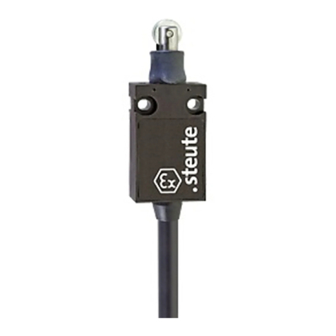
steute
steute Ex 14 Programming manual
steute
steute STM 295 Programming manual
steute
steute STM 295 Programming manual
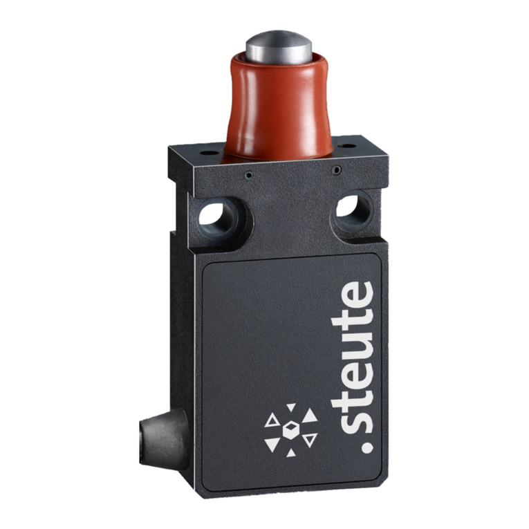
steute
steute ES 14 Extreme Series Programming manual
steute
steute RF BF 72 SW868 Programming manual
steute
steute EX STM 515 Programming manual

steute
steute STM 295 Programming manual
steute
steute Ex STM 298 3G/D Series Programming manual
steute
steute STM 295 Programming manual
steute
steute Ex AZM 415 Programming manual
