Trunsun Solar TSMxxx-72 series User manual

1
Installation Manual
General Installation Manual for TRUNSUN SOLAR PV Solar Module
Please read this manual carefully before installing the modules.
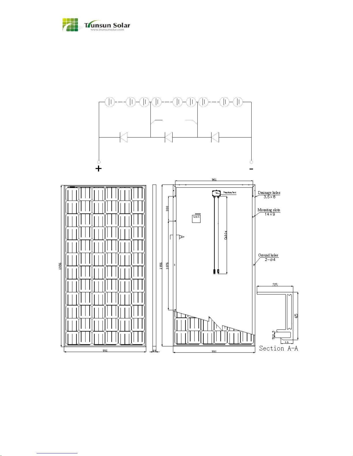
Module components and cross-section
1 WARNING
Please read this manual completely before
installing TRUNSUN SOLAR module. This
module produces electricity when exposed to
light. Follow all applicable electrical safety
precautions. Only qualified personnel should
install or perform maintenance work on this
module. Do not handle modules when they are
wet. Do not use mirrors or other magnification
device or artificially concentrate sunlight onto
the modules.
2 INTRODUCTIONS
TRUNSUN SOLAR modules come in various
sizes to satisfy a full range of applications.
Each module is made of crystalline-silicon cells.
To protect the cells from the most severe
-environmental conditions, modules are made
of high transmission rate and low iron tempered
glass, anti-aging encapsulation material, and
high climate resistant and insulation backsheet
by hot lamination, with anodized Aluminum
alloy frame and permanently attached junction
box.
3 APPLICATIONS
Modules are reliable,designed to operate
efficiently in sunlight. By modules, the solar
radiant energy is transformed into electrical
energy for using. Modules, usually are used as
one fitting of PV solar system. A set of basic PV

2
solar system is consisted of PV solar modules,
controller, inverter, and storage battery.
Modules can be used in roof PV solar systems,
PV stations, building, and other electric
generation application etc widely.
4 CODES and REGULATIONS
The mechanical and electrical installation of PV
systems should be performed in accordance
with all applicable codes; including electrical
codes, building codes, and electric utility
interconnect requirements.
Requirements may also vary with system
voltage, and for DC or AC application. Contact
local authorities for governing regulations.
Whatever district, local standards should also
be followed in such installations.
Use only stranded or solid copper single
–conductor type PV wire or USE-2 cable, rated
sunlight resistant, for modules and interconnect
wiring that is exposed to weather.
5 MECHANICAL INSTALLATIONS
5.1 Mounting Site
Modules can be used on land except for
corrosive salt area and sulfurous area.
Excluded applications include, but are not
limited to, installations where modules are likely
to come in contact with any salt water or where
likely to become partially or wholly submerged
in fresh or salt water, examples of which include
use on boats, docks and buoys. Don’t install
modules in a location where it would be
immersed in water or continually exposed to
water from a sprinkler or fountain etc.
Actual maximum allowable wind speed may be
influenced by module type, mounting
configuration, location, and other factors. In no
case should modules be exposed to pressures
greater than 112.9pounds per square foot
(551Kg/m2) of uniformly distributed wind, snow,
or other loading.
The modules have been tested by TUV for a
maximum front loading of 5400Pa,backside
loading of 2400Pa.
Don’t install modules near naked flame or
flammable materials.
When choosing a site, avoid trees, buildings or
obstructions. Modules should be mounted to
maximize direct exposure to sunlight and to
eliminate or minimize shadowing. Even partial
shadowing can substantially reduce module
and system output. Furthermore, partial
shadowing can elevate the shaded portion’s
internal temperature, which may lower the
output and shorten module life.
5.2 Orientation of installations
Modules may be mounted at any angle from a
vertical orientation to a horizontal one. The
appropriate fixed tilt angle and azimuth
orientation should be used in order to maximize
the exposure to sunlight.
Incorrect orientation of modules installation will
result in loss of power output. Modules
connected in series should be installed at same
orientation and angle. Different orientation or
angle may cause loss of power output due to
difference of amount of sunlight exposed to the
modules.
In the Northern Hemisphere, modules should
face south, and in the Southern Hemisphere,
modules should face north.
5.3 Module tilt angle
Modules produce the most power when they
are pointed directly at the sun. For installations
where modules are mounted to a permanent
structure, modules should be tilted for optimum
winter performance. As a rule, if the PV system
power production is adequate in the winter, it
will be satisfactory during the rest of the year.
The module tilt angle is measured between the
modules and the ground.
5.4 Mounting

3
Use fasteners to fasten the modules to the
mounting support structure. Modules should be
bolted to support structures through mounting
holes located in the frame’s back flanges only.
Do not drill additional holes in the frame. Doing
so will invalidate the warranty. Modules should
not be mounted by supports at the ends.
Mounting support structure should withstand
forces from wind and snowfall pressure etc.
Mounting support structure should use proper
materials and corrosive treatment. Installation
the modules should have proper ventilation.
Clearance behind the modules is required to
permit air circulation and cooler module
operation. Elevated temperatures lower
operating voltage and power, and shorten
module lifetime. Clearance of 1/4 inch (6.35mm)
or more between modules is required to allow
for thermal expansion of the frames.
The recommended standoff height is 4.5 inch
(about 115 mm). If other mounting means are
employed it would cause unpredictable effect.
Figure 1:
Mounting holes for normal installation
Module must be securely attached to the
mounting structure using 8 holes for normal
installation as indicated in figure 1. Load
calculations shall be done by the system
designer or installer.
Each hole shall be installed in the order as in
the following figure.
Figure 2:
For your reference,please use the components
specified in below:
1.Bolt(inside hexagonal)
Material:Stainless Steel
Size and Length: M8*16mm
(M6*16 for TSP-54&TS*-60)
2.Washer
Material:Stainless Steel
Size:M8 (M6*16 for TSP-54&TS*-60)
3.Spring Washer
Material: Stainless Steel
Size:M8 (M6*16 for TSP-54&TS*-60)
4.Nut
Material: Stainless Steel
Size:M8 (M6*16 for TSP-54&TS*-60)
Remark: TS*-60 means TSM-60 & TSP-60
Recommended torque is between 14N.m to
20N.m.
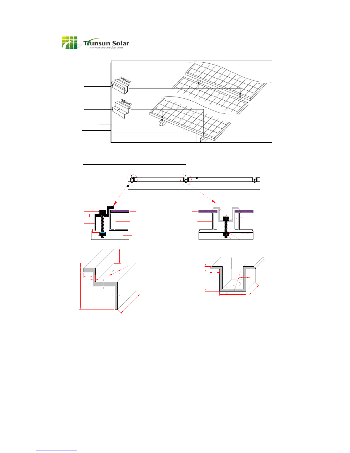
Modules should be mounted using specialized
clamps as shown in Figure 3.
1.Modules should be attached on a supporting
structure rail by metal clamps. It is recommended
to use the clamps under the following condition or
approved by the system installation. At the edge
installation, using the similar clamp which can be
matched to the clamp in figure 3.
2.Recommended bolt (M8) torque rang:18N.m to
24N.m.
3.The Modules clamps must not contact the front
glass or deform the frame in any way. Avoid
shading effects from the Module clamps.
Drainage holes on the Modules frame must not
be closed or obscured by the clamps.
4
Figure 3: Clamp Details (Units: mm)
5.4.1 Roof mount
1. When installing a module on a roof or
building, ensure that it is securely and
cannot fall as a result of wind or snow
loads.
2. Provide adequate ventilation under a
module for cooling (5cm minimum air
space between module and mounting
surface).
3. The module is in a minimum fire resistance
rating of Class C, and the fire rating of this
module is valid only when mounted in the
manner specified in the mechanical
mounting instructions.
4. When installing module on a roof, ensure
that the roof construction is suitable. In
addition, any roof penetration required to
mount the module must be properly sealed
to prevent leaks.
5. In some cases, a special support frame
may be necessary.
6. The roof installation of solar modules may
affect the fireproofing of the house
construction. This module has a Class C
Fire Rating and must be installed over a
roof which is with appropriate fire
resistance.
Bolt
Washer
Clamp A
Washer
Spring Washer
Nut
PV laminate
Alumlnum
Frame
Substructure
rails
PV
laminate
Alumlnum
Frame
Substructure
rails
Nut Spring Washer
Washer
Washer
Bolt
Clamp B
Metal clamp B
(min.2 places)
Metal clamp A
(min.2 places)
Mountiing Structure Rail
Solar module
Metal clamp B
Metal clamp A
Mountiing Structure Rail
3
9-11
25,5
30
3
3
≥38
(recommendation)
(recommendation)
Clamp B
5
X
9-11
3
5
3
16
≥38
C
lamp A(X=height of Modules frame)
φ8-9
φ8-9
5
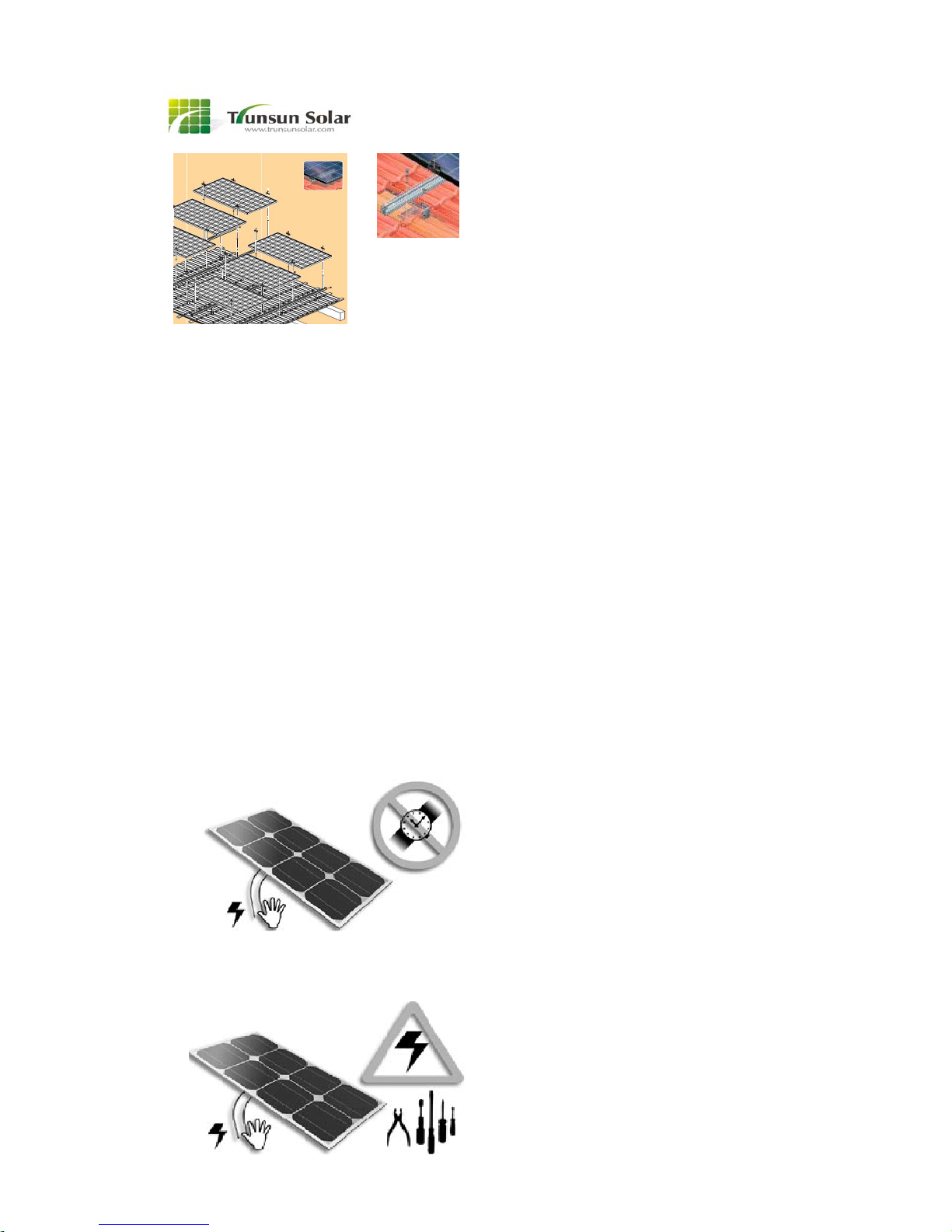
5.4.2 System mount
1. Solar modules produce electrical energy
when light shines on their front surface.
The DC voltage may exceed 30V. If
modules are connected in series, the total
voltage is equal to the sum of the individual
module voltage. If modules are connected
in parallel, The total current is equal to the
sum of the individual module current. Do
not disconnect during load connection for a
removable connector.
2. Keep children away from the system while
transporting and installing mechanical and
electrical components.
3. Completely cover the module with an
opaque material during installation to keep
electricity from being generated.
4. Do not wear metallic rings,
watchbands,ear,nose,lip rings or other
metallic devices while installing or
troubleshooting photovoltaic systems.
Only use approved insulate tools for
electrical installation work.
5. Abide with safety regulations for all other
components used in system, including
wiring and cables,connectors,charging
regulators,inverters,storage batteries and
rechargeable batteries,etc.
6. Use only equipment,connectors,wiring and
support frames suitable for use in a solar
electric system. Always use the same type
of module within a particular photovoltaic
system.
6 ELECTRICAL INSTALLAIONS
6.1 Bypass diodes
Modules contain bypass diodes when shipped
from the factory.
If the service personnel need to replace the
damaged bypass diodes, at least one diode
should be installed in each string.
Only qualified personnel are permitted to install
the bypass diodes.
Open the cover of junction box and install
diodes in each two conductors. Only diode with
the same model type is permitted to be used.
6.2 Over current protection
Whenever necessary to comply with local
codes, use a fuse or circuit breaker, rated for
the maximum series fuse rating of the module
and the system voltage.
Always fuse the connections at the battery for
safety. Refer to the module rating label (on
module) for recommended fuse size. Also, refer
to the charge controller owner’s manual.
When the modules are connected in parallel,
each module or each string of module shall be
provided with a fuse with the maximum series
fuse rating as indicated in “Electrical
Specification”.
All electrical components should have ratings
equal or greater to the system rating. Do not
exceed the maximum allowable system voltage
as listed on the module label.
6
6.3 Grounding
Trunsun Solar modules use an anodic oxidized
aluminum frame to resist corrosion. So the
frame of modules must be connected to the
equipment grounding conductor to prevent
thunder and static injury. The grounding device
must be fully contact with the inside of the
aluminum alloy, and must penetrate the surface
of the frame oxidation film.
Please don’t drill any additional grounding hole
on the frame of the modules.
For optimal performance, Trunsun Solar
recommend the DC cathode of the modules
array is connected to ground. Failure to comply
whit this requirement may reduce the
performance of the system.
The grounding method must not result in direct
contact of dissimilar metals with the aluminum
frame of the modules that will result in galvanic
corrosion. An addendum to UL standard 1703
“Flat Plate Photovoltaic Modules and Panels”
recommends metal combinations not exceed
electrochemical potential difference of 0.6 volts.
The frame rails have pre-drilled holes marked
with is a grounding sing. These holes should
be used for grounding purpose and must not be
used for mounting the modules. The following
grounding methods are available.
There is a grounding hole 4.0mm diameter on
the edge side closer to the middle of the back
frame of module. All module frames should be
grounded for safety. The grounding
connections between modules must be
approved by a qualified electrician, the
grounding itself must be made by a qualified
electrician. The grounding clip accepts solid
uninsulated copper wire sizes 12 AWG. The
wire must not be nicked.
The module shall wire in accordance with the
standard, the grounding method of the frame of
arrays shall comply with IEC 61215. Of course,
in accordance with local laws and regulations to
carry out electrical installation is the best
choice.
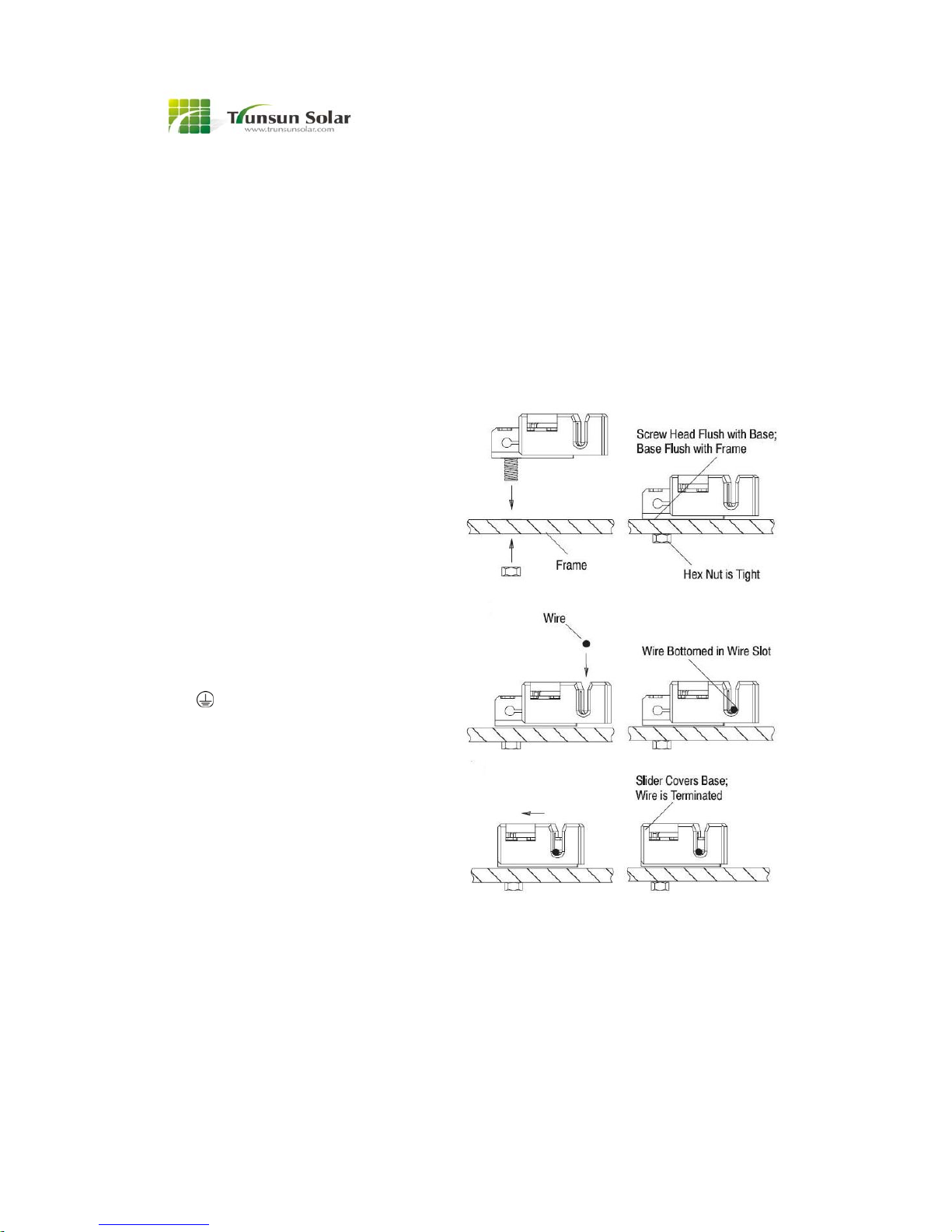
Use the UL listed grounding clip manufactured
by Tyco Electronics Corp with type name
1954381-2. Place the grounding clip onto the
module frame so that the screw straddles the
grounding hole, then tighten the screw and nut
with a torque 2.3 to 2.8 Nm. The head of the
screw must be flush with the base and the base
must be flush with the frame. The copper wire
should not be compressed during the
installation.
Place a 12 AWG copper wire in the wire slot
then engage the slider. Detailed process is as
the following:
Figure 4
Trunsun solar modules can be grounded using
third party grounding devices so long as the are
certified for grounding modules and the devices
are installed according to the manufactures’s
specified instructions.
6.4 Wiring
Modules are equipped with factory installed
wires and quick connectors. Modules have
been designed to be easily interconnected in
series.
Bolt diameter is
4mm.

7
One module has a pair of male and female
waterproof cables and connectors for electrical
connection, that are pre-wired inside the
junction box. The cables have obvious marks of
the positive and the negative.
For a series electrical connection, connect
positive (+) connector of one module to the
negative (-) connector of the following module.
For a parallel electrical connection, connect
positive (+) connector of one module to the
positive (+) connector of the following module.
Figure 5
(1) serial -connection of modules
(2) parallel- connection of modules
For parallel connection, additional branch
connectors are needed. The module employs
connectors manufactured by Multi-Contact USA
with model type PV-KBT4/6II-UR (female) and
PV-KST4/6II-UR (male) or connectors
manufactured by other manufactories which
also can be matched to the connector of
Multi-Contact, check the connectors in the
module and choose branch connectors that
match the connectors of the modules.
Use 12 AWG or 14 AWG PV wire or USE-2 wire
for interconnection. The area of the cable
mated with the connector is recommended to
be 4mm², temperature range:-40℃to 90℃.
When connecting the modules to load or on
inverter, additional wires with pre-attached
connectors may be used. The wire shall be PV
wire or USE-2 wire, the connectors shall be
manufactured by Multi-Contact USA with model
type PV-KBT4/6II-UR (female) and
PV-KST4/6II-UR (male) or shall be
manufactured by other manufactories which
also can be matched to the connector of
Multi-Contact. Connect this wire to the module
by connectors, then the other end of the wire is
connecting to inverter or load by field wiring
method specified by inverter/ load
manufacturers.
7 MAINTENANCES
It is recommended to check the modules once
per year. Under most conditions, normal rainfall
is sufficient to keep the module glass clean. If
dirt build-up becomes excessive, clean the
glass with a soft cloth using mild detergent and
water. Modules that are mounted, flat (0°tilt
angle) should be cleaned more often, as they
will not self-clean as effectively as modules
mounted at a 15°tilt or greater.
It is recommended to perform periodic
inspection of the modules for damage to glass,
back skin, frame, and support structure. Check
electrical connections for loose connections
and corrosion. Check if mounting support
structure and modules are loose. Check
connections of cables, connectors, and
grounding.
All the modules have to pass comprehensive in
spection before delivery, which ensures that all
the modules can meet the requirements of the

8
Customers
The fault probability of the modules in the later
operation is extremely low.
You can use the below fault judgment methods:
apperance defects, such as break, cracked, su
rface stripping and so on, the electrical perform
ance of the whole string or of the whole module
failed.
For the fault modules, you cannot disassemble
them by yourself. Disassembling must be exec
uted by qualified experts. You should contact o
ur sales persons at once to apply for repaire or
replacement of the fault modules. (the modules
need to be replaced must be the same kind a
nd type ,if needed) .
Modules can operate effectively without ever
being washed, although removal of dirt from the
front glass can increase output. The glass can
be washed with a wet sponge or cloth. Wear
rubber gloves for electrical insulation.
8 SAFETY PRECAUTIONS
Module installation and operation should be
performed by qualified personnel only. Children
should not be allowed near the solar electric
installation. Modules of unpacking, transport,
installation process must be handled with care.
To avoid collision with the sharp and hard
objects so as not to cause damage and affect
the normal use.
Module must be installed in the absence of
shadowed areas, otherwise it will not work to
generate electricity. If the module long
shadowing state (dust and bird feces shadowed)
to work, it will Breakdown caused by
overheating
Avoid electrical hazards when installing, wiring,
operating and maintaining the module. Modules
produce DC electricity when exposed to light
and therefore can produce an electrical shock
or burn. Modules produce voltage even when
not connected to an electrical circuit or load.
Modules produce nearly full voltage when
exposed to as little as 5% of full sunlight and
both current and power increase with light
intensity. Do not touch live parts of cables and
connectors. As an additional precaution, use
insulated tools and rubber gloves when working
with modules in sunlight.
Fall of modules from high place will cause
death, injury or damage. Do not drop module or
allow objects to fall on module. Never leave a
module unsupported or unsecured. If a module
should fall, the glass can break. A module with
broken glass cannot be repaired and must not
be used.
When installing or working with module or
wiring, cover module face completely with
opaque material to halt production of electricity.
Modules have no on/off switch. Modules when
exposed to sunlight generate high voltage and
are dangerous. Modules can be rendered
inoperative only by removing them from
sunlight, or by fully covering the front surface
with opaque cloth, cardboard, or other
completely opaque material, or by working with
modules face down on a smooth, flat surface
when installing or maintaining.
Do not expose the artificially concentrated
sunlight to a module.
Trunsun modules are designed to fulfill the
criteria of Application class A requirements
according to IEC61730-1.Modules rated for use
in application class A may be used in systems
operating at greater than 50V DC or 240W,
where general contact access is anticipated.
Modules qualified for safety through
IEC61730-1 and IEC61730-2 within application
class A are considered to meet the
requirements for safety class Ⅱreferring to
IEC61140.
Modules can produce higher output than the
rated specifications. Industry standard ratings
are made at conditions of 1000 W/m2 and 25°C
cell temperature. Reflection from snow or water
can increase sunlight and therefore boost
current and power. In addition, colder
temperatures can substantially increase voltage
and power. Modules are intended for use in
terrestrial

9
applications only, thus excluding aerospace or
maritime conditions or use with sunlight
concentration.
It is recommended that the module remains
packed in the box until time of installation .Work
only under dry conditions, with a dry module
and tools.
Since sparks may be produced, do not install
module where flammable gases or vapors are
present.
Do not drill holes into module frame as it will
void warranty.
Modules are constructed with tempered glass,
but still must be handled with care. If the front
glass is broken or if the polymer back skin is
torn, contact with any module surface or the
frame can produce electrical shock, particularly
when the module is wet. Broken or damaged
modules must be disposed of properly. Do not
disassemble, bend, impact by sharp objects,
walk on, and throw or drop etc. Keep back
surface free from foreign objects. Avoid sharp
edges.
Use module for its intended function only.
Follow all module manufacturer’s instructions.
Do not disassemble the module, or remove any
part or label installed by the manufacturer. Do
not treat the back of the module with paint or
adhesives.
If not otherwise specified, it is recommended
that requirements of the latest local, national or
regional electrical codes be followed.
Retain this installation manual for future
reference.
9 NOTES
The installation shall be in accordance with
CSA C22.1, Safety Standard for Electrical
Installation, Canadian Electrical Code, Part 1.
Under normal conditions, a photovoltaic module
is likely to experience conditions that produce
more current and/or voltage than reported at
standard test conditions. Accordingly, the
values of Isc and Voc marked on this module
should be multiplied by a factor of 1.25 when
determining voltage ratings, conductor current
ratings, fuse sizes, and size of controls
connected to the module output. Refer to
Section 690-8 of the U.S. National Electrical
Code for an additional multiplying factor of 1.25,
which may be applicable.
For modules with a nominal open voltage or
maximum system voltage of 45V or more may
cause an electric shock.
The current output for the modules shown in
the Specifications is measured at Standard Test
Conditions. These conditions may not be
frequently observed in actual practice.
10
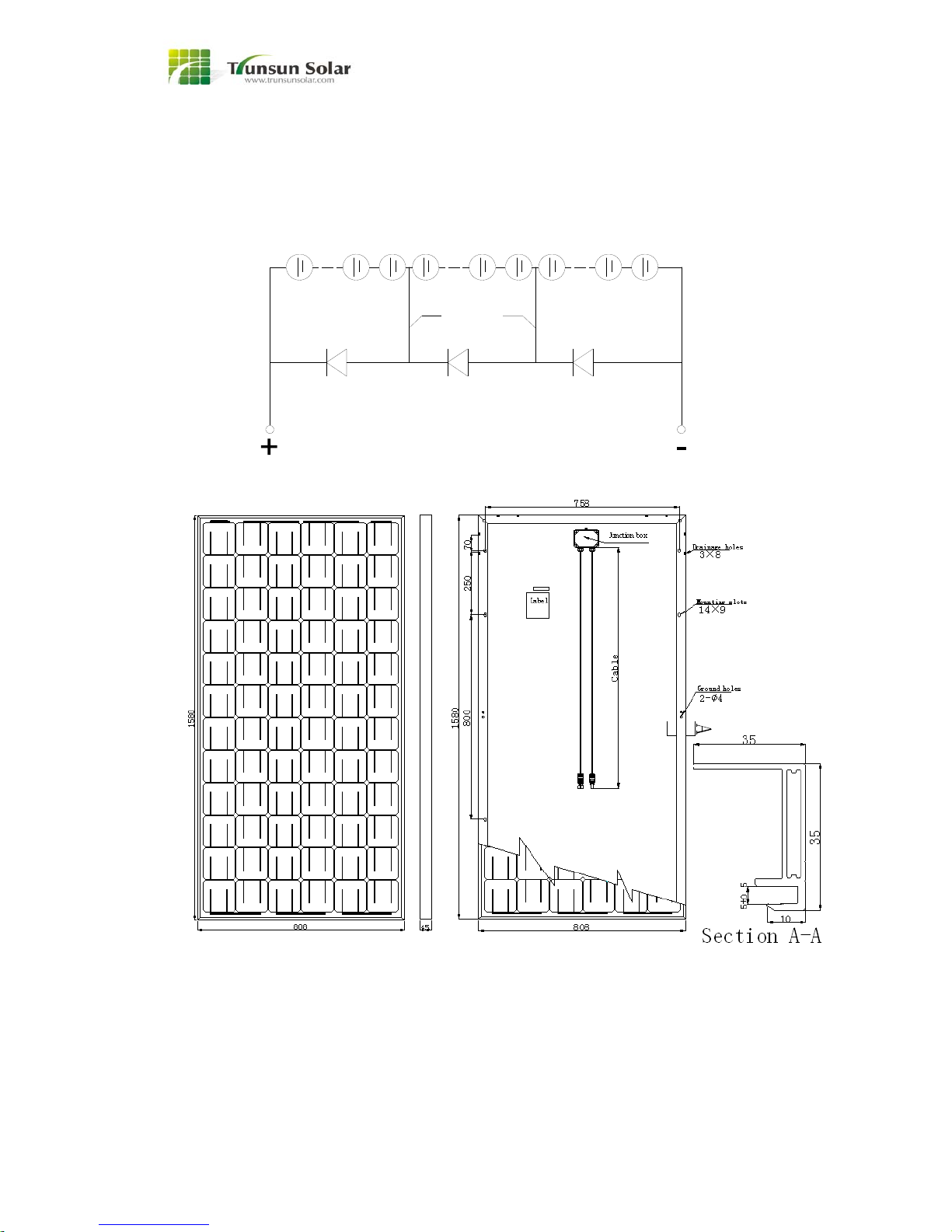
SPECIFICATIONS-1
Zhejiang Trunsun Solar single crystalline silicon PV module---TSMxxx-72
NOTE: TSM-72
Electrical Specification and Mechanical Specification can be found in the last page <Electrical
Specification and Mechanical Specification>
D
C
down-lead
24 cells 24 cells 24 cells
AB
output output
11
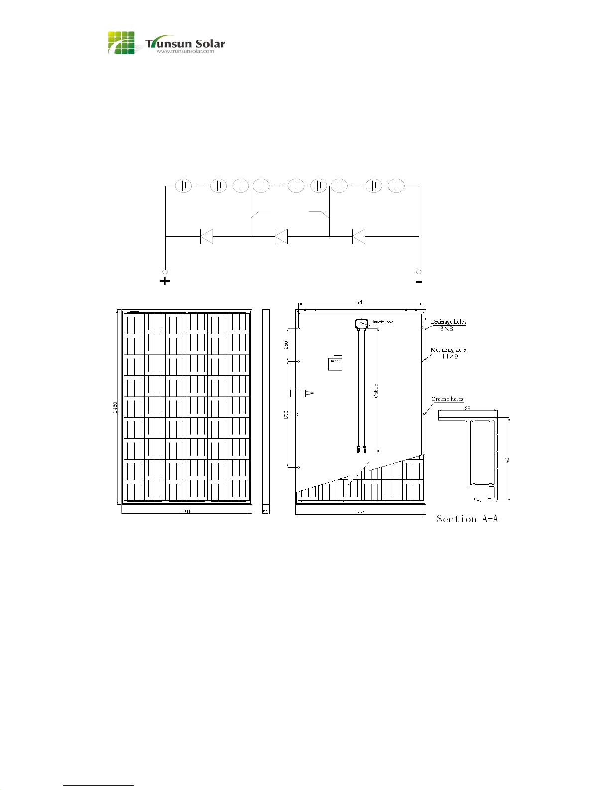
SPECIFICATIONS-2
Zhejiang Trunsun Solar single crystalline silicon PV module---TSPxxx-54
NOTE: TSP-54
Electrical Specification and Mechanical Specification can be found in the last page <Electrical
Specification and Mechanical Specification>
D
C
down-lead
18 cells 18 cells 18 cells
A B
output output
12
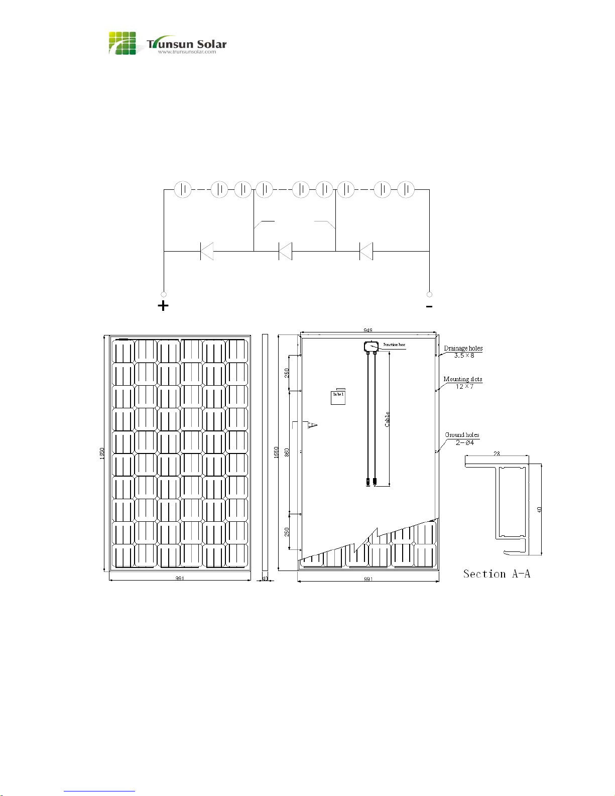
SPECIFICATIONS-3
Zhejiang Trunsun Solar single crystalline silicon PV module---TSMxxx-60
NOTE: TSM-60
Electrical Specification and Mechanical Specification can be found in the last page <Electrical
Specification and Mechanical Specification>
D
C
down-lead
20 cells 20 cells 20 cells
AB
output output
13
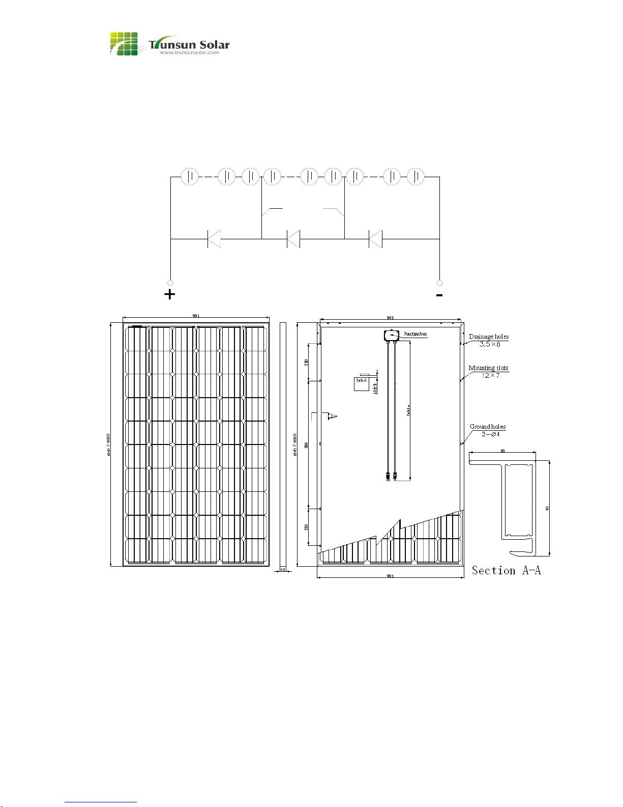
SPECIFICATIONS-4
Zhejiang Trunsun Solar single crystalline silicon PV module---TSMxxx-60
NOTE: TSM-60
Electrical Specification and Mechanical Specification can be found in the last page <Electrical
Specification and Mechanical Specification>
D
C
down-lead
20 cells 20 cells 20 cells
AB
output output
14
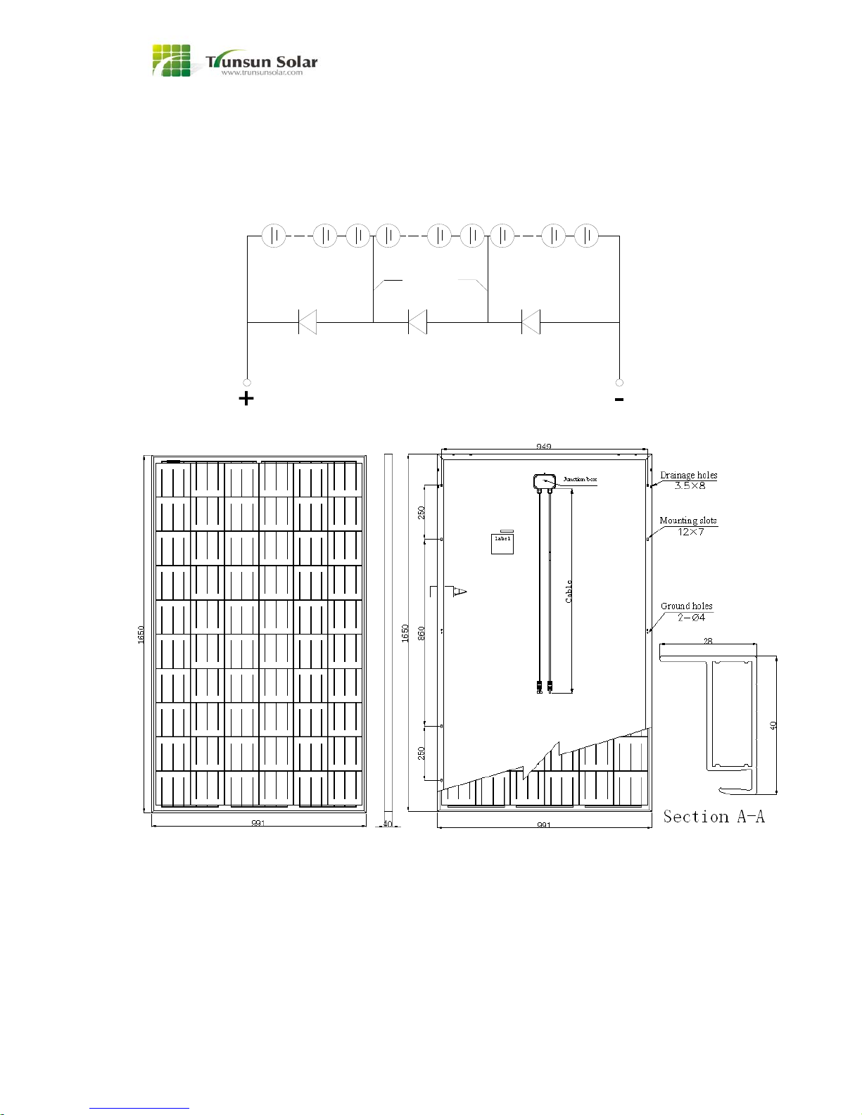
SPECIFICATIONS-5
Zhejiang Trunsun Solar single crystalline silicon PV module---TSPxxx-60
NOTE: TSP-60
Electrical Specification and Mechanical Specification can be found in the last page <Electrical
Specification and Mechanical Specification>
D
C
down-lead
20 cells 20 cells 20 cells
AB
output output

15
SPECIFICATIONS-6
Zhejiang Trunsun Solar single crystalline silicon PV module---TSPxxx-60
NOTE: TSP-60
Electrical Specification and Mechanical Specification can be found in the last page <Electrical
Specification and Mechanical Specification>
D
C
down-lead
20 cells 20 cells 20 cells
AB
output output
16
SPECIFICATIONS-7
Zhejiang Trunsun Solar single crystalline silicon PV module---TSMxxx-72
NOTE: TSM-72
Electrical Specification and Mechanical Specification can be found in the last page <Electrical
Specification and Mechanical Specification>
D
C
down-lead
24 cells 24 cells 24 cells
AB
output output

17
SPECIFICATIONS-8
Zhejiang Trunsun Solar single crystalline silicon PV module---TSMxxx-72
NOTE: TSM-72
Electrical Specification and Mechanical Specification can be found in the last page <Electrical
Specification and Mechanical Specification>
D
C
down-lead
24 cells 24 cells 24 cells
AB
output output

18
SPECIFICATIONS-9
Zhejiang Trunsun Solar single crystalline silicon PV module---TSPxxx-72
NOTE: TSP-72
Electrical Specification and Mechanical Specification can be found in the last page <Electrical
Specification and Mechanical Specification>
D
C
down-lead
24 cells 24 cells 24 cells
AB
output output

19
SPECIFICATIONS-10
Zhejiang Trunsun Solar single crystalline silicon PV module---TSPxxx-72
NOTE: TSP-72
Electrical Specification and Mechanical Specification can be found in the last page <Electrical
Specification and Mechanical Specification>
D
C
down-lead
24 cells 24 cells 24 cells
AB
output output
20
Electrical Specification and Mechanical Specification
Model Cell
Type Cell
number Cell
connection
Module
weight
(kg)
Module
size(mm) Max.
Power
Max.
system
voltage Voc (V) Isc (A) Vpm
(V) Ipm
(A) Eff(%) IEC
Application
Class
Fire
Class
Maximum
over-current
protection
rating (A)
Recommended
maximum
series/parallel
module
configurations
TSM175-72 Mono 72 6*12 16 1580*808*45*35 175 1000 42.60 5.52 35.50 4.93 13.7 A C 15 23/1
TSM180-72 Mono 72 6*12 16 1580*808*45*35 180 1000 42.60 5.68 35.50 5.07 14.1 A C 15 23/1
TSM185-72 Mono 72 6*12 16 1580*808*45*35 185 1000 43.20 5.76 36.00 5.14 14.5 A C 15 23/1
TSM190-72 Mono 72 6*12 16 1580*808*45*35 190 1000 43.20 5.91 36.00 5.28 14.9 A C 15 23/1
TSM195-72 Mono 72 6*12 16 1580*808*45*35 195 1000 43.20 6.07 36.00 5.42 15.3 A C 15 23/1
TSM200-72 Mono 72 6*12 16 1580*808*45*35 200 1000 43.20 6.22 36.00 5.56 15.7 A C 15 23/1
TSM205-72 Mono 72 6*12 16 1580*808*45*35 205 1000 43.80 6.29 36.50 5.62 16.1 A C 15 22/1
TSM210-72 Mono 72 6*12 16 1580*808*45*35 210 1000 43.80 6.44 36.50 5.75 16.4 A C 15 22/1
TSP190-54 Poly 54 6*9 17.5 1480*991*50*35 190 1000 30.80 8.28 25.70 7.39 13.0 A C 15 32/1
TSP195-54 Poly 54 6*9 17.5 1480*991*50*35 195 1000 30.80 8.50 25.70 7.59 13.3 A C 15 32/1
TSP200-54 Poly 54 6*9 17.5 1480*991*50*35 200 1000 31.30 8.58 26.10 7.66 13.6 A C 15 31/1
TSP205-54 Poly 54 6*9 17.5 1480*991*50*35 205 1000 31.30 8.80 26.10 7.85 14.0 A C 15 31/1
TSP210-54 Poly 54 6*9 17.5 1480*991*50*35 210 1000 31.80 8.88 26.50 7.92 14.3 A C 15 31/1
TSP215-54 Poly 54 6*9 17.5 1480*991*50*35 215 1000 31.80 9.09 26.50 8.11 14.7 A C 15 31/1
TSP220-54 Poly 54 6*9 17.5 1480*991*50*35 220 1000 32.30 9.16 26.90 8.18 15.0 A C 15 30/1
TSP225-54 Poly 54 6*9 17.5 1480*991*50*35 225 1000 32.30 9.37 26.90 8.36 15.3 A C 15 30/1
TSP230-54 Poly 54 6*9 17.5 1480*991*50*35 230 1000 32.80 9.44 27.30 8.42 15.7 A C 15 30/1
TSM245-60 Mono 60 6*10 18.5 1640*991*40*28 245 1000 38.32 8.52 30.94 7.92 15.1 A C 15 26/1
TSM250-60 Mono 60 6*10 18.5 1640*991*40*28 250 1000 38.55 8.64 31.21 8.01 15.4 A C 15 25/1
TSM255-60 Mono 60 6*10 18.5 1640*991*40*28 255 1000 38.76 8.72 31.37 8.13 15.7 A C 15 25/1
TSM260-60 Mono 60 6*10 18.5 1640*991*40*28 260 1000 38.92 8.81 31.67 8.21 16.0 A C 15 25/1
TSM265-60 Mono 60 6*10 18.5 1640*991*40*28 265 1000 39.12 8.89 31.97 8.29 16.3 A C 15 25/1
TSM270-60 Mono 60 6*10 18.5 1640*991*40*28 270 1000 39.25 8.98 32.30 8.36 16.6 A C 15 25/1
TSM275-60 Mono 60 6*10 18.5 1640*991*40*28 275 1000 39.36 9.09 32.55 8.45 16.9 A C 15 25/1
This manual suits for next models
69
Table of contents
Popular Solar Panel manuals by other brands

Baxi
Baxi Solargen PHOTOVOLTAIC manual

Schumacher Electric
Schumacher Electric SP-5400 owner's manual

Viessmann
Viessmann Vitovolt 300 operating instructions

Tycon Power Systems
Tycon Power Systems RPDC-12 Series quick start guide

Viessmann
Viessmann VITOSOL-F Service instructions

Lippert
Lippert Furrion FSFP37MW2-BL user manual


