SLS LAB BASICS SLS2600 User manual

SLS Lab Basics
Mini Vacuum Pumps
United Kingdom:
International:
Northern Ireland:
Republic of Ireland:
Code: SLS2600/2602 |User Manual

1. About this document.....................................................................................................................3
2. Use ................................................................................................................................................4
3. Safety ............................................................................................................................................5
4. Technical Data ............................................................................................................................. 7
5. Design and Function ..................................................................................................................10
6. Installation and connection.........................................................................................................11
7. Operation.....................................................................................................................................12
8. Servicing......................................................................................................................................14
9.Troubleshooting............................................................................................................................17
10. Spare parts and accessories.....................................................................................................19
SLS Lab Basics Mini Vacuum Pumps SLS2600/2602
Contents

3
SLS Lab Basics Mini Vacuum Pumps SLS2600/2602
1 .About this document
1.1. Using the Operating Instructions
The Operating Instructions are part of the pump.
►Carefully study the Operating Instructions before using a pump.
► Always keep the Operating Instructions handy in the work area.
►Pass on the Operating Instructions to the next owner.
1.2. Symbols and Markings
Warning
A danger warning is located here.
Possible consequences of a failure to observe the warning are specified here.
The signal word, e.g. Warning, indicates the danger level.
►Measures for avoiding the danger and its consequences
are specified here.
WARNING
Warning
Signal word Meaning Consequences if not observed
DANGER Warns of immediate danger Death or serious injuries and/or serious
damage are the consequence.
WARNING Warns of immediate danger Death or serious injuries and/or serious
damage are possible.
CAUTION Warns of a possibly dangerous situation Minor injuries or damage are possible.
Table. 1
Other information and symbols
►An activity to be carried out (a step) is specified here.
1. The first step of an activity to be carried out is specified here.
Additional, consecutively numbered steps follow.
iThis symbol refers to important information.

SLS Lab Basics Mini Vacuum Pumps SLS2600/2602
4
2 .Use
2.1. Proper use
The pumps are exclusively intended for transferring gases and
vapours.
Owner’s responsibility
Only install and operate the pumps under the operating parameters
and conditions described in chapter 4, Technical data.
Make sure that the installation location is dry and the pump is
protected against rain, splash, hose and drip water.
Before using a medium, check whether the medium can be
transferred danger-free in the specific application case.
Before using a medium, check the compatibility of the materials of
the pump head, diaphragm and valves with the medium.
Only transfer gases which remain stable under the pressures and
temperatures occurring in the pump.
Laboratory equipment or additional components connected to a
pump have to be suitable for use with the pneumatic capabilities of
the pump.
2.2. Improper use
The pumps may not be operated in an explosive atmosphere.
The pumps are not suitable for transferring dusts.
The pumps are not suitable for transferring liquids.
The pumps must not be used to create vacuum and overpressure
simultaneously.
An overpressure must not be applied to the suction side of the pump.
Operating parameters
and conditions
Requirements for
transferred medium
Accessories

SLS Lab Basics Mini Vacuum Pumps SLS2600/2602
3 .Safety
iNote the safety precautions in chapters 6. Installation and connection,
and 7. Operation.
The pumps are built according to the generally recognized rules of
technology and in accordance with the occupational safety and
accident prevention regulations. Nevertheless, dangers can result
during their use which lead to injuries to the user or others, or to
damage to the pump or other property.
Only use the pumps when they are in a good technical and proper
working order, in accordance with their intended use, observing the
safety advice within the operating instructions, at all times.
Make sure that only trained and instructed personnel or specially
trained personnel work on the pumps. This especially applies to
assembly, connection and servicing work.
Make sure that the personnel has read and understood the operating
instructions, and in particular the “Safety” chapter.
Observe the accident prevention and safety regulations when
performing any work on the pump and during operation.
Do not expose any part of your body to the vacuum.
Open housing parts with notice sticker (see fig. 1) only after
separating mains plug from power source.
When transferring dangerous media, observe the safety regulations
when handling these media.
Be aware that the pumps are not designed to be explosion-proof.
Make sure the temperature of the medium is always sufficiently
below the ignition temperature of the medium, to avoid ignition or
explosion. This also applies for unusual operational situations.
Note that the temperature of the medium increases when the pump
compresses the medium.
Hence, make sure the temperature of the medium is sufficiently
below the ignition temperature of the medium, even when it is
compressed to the maximum permissible operating pressure of the
pump. The maximum permissible operating pressure of the pump
is stated in the technical specifications (see chapter 4).
If necessary, consider any external sources of energy, such as
radiation, that may add heat to the medium.
In case of doubt, consult the SLS customer service.
Store all replacement parts in a protected manner and dispose of them
properly in accordance with the applicable environmental protection
regulations. Observe the respective national and international regulations.
This especially applies to parts contaminated with toxic substances
.
5
Personnel
Working in a safety
conscious manner
Handling dangerous
media
Handling flammable
media
Environmental
protection
Fig. 1: Notice sticker

SLS Lab Basics Mini Vacuum Pumps SLS2600/2602
6
The pumps conform to the Directive 2011/65/EU (RoHS2).
The pumps conform to the safety regulations of the Directive
2014/30/EU concerning Electromagnetic Compatibility and the
Directive 2006/42/EC concerning Machinery.
The following harmonized standards have been used:
• DIN EN 61010-1
• DIN EN 61000-3-2/3
• DIN EN 55014-1/2
• DIN EN 50581
• DIN EN 1012-2
• DIN EN ISO 12100
The pumps correspond to IEC 664:
• the overvoltage category II
• the pollution degree 2
Standards

SLS Lab Basics Mini Vacuum Pumps SLS2600/2602
7
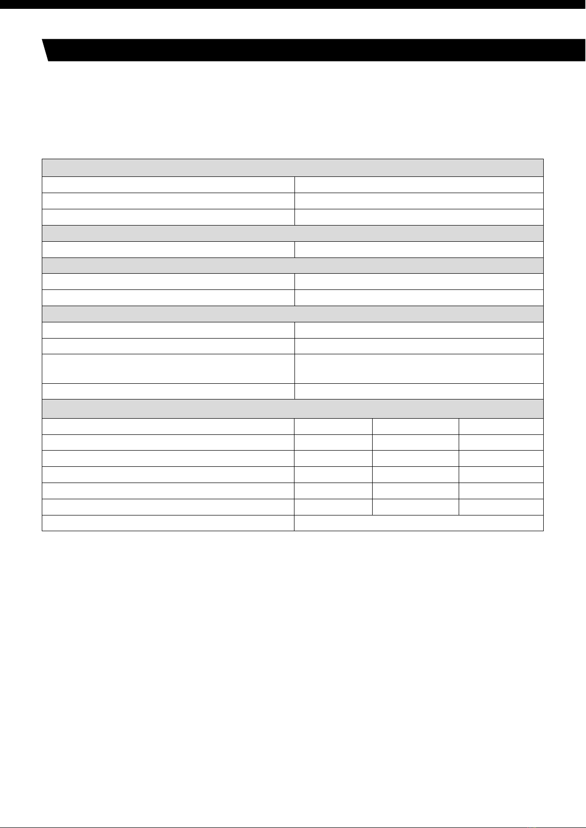
4 .Technical Data
Component Pump material
Pump head PPS
Diaphragm EPDM
Valve plates/sealings FPM
iAll pumps are secured against overheating with thermal switches and are equipped with a
mains fuse.
Pump materials
SLS2600
SLS2602
Component Pump material
Pump head PPS
Diaphragm PTFE-coated
Valve plates/sealings FFPM
Table. 2
Table. 3
iRefer to the type plate for the pump’s electrical configuration.
SLS Lab Basics Mini Vacuum Pumps SLS2600/2602
Pneumatic performance
Max. permissible operating pressure [bar g] 2.4
Ultimate vacuum [mbar abs.] 100
Delivery rate at atm. pressure [l/min]* 6.0
Pneumatic connections
Hose connection [mm] ID 4
Ambient and media temperature
Permissible ambient temperature + 5 °C to + 40 °C
Permissible media temperature + 5 °C to + 40 °C
Other parameters
Weight [kg] 1.9
Dimensions: L x H x W [mm] 164 x 141 x 90
Maximum permissible ambient relative humidity 80% for temperatures up to 31 °C, decreasing
linearly to 50 % at 40 °C
Max. altitude of site [m above sea level] 2000
SLS2600
Electrical Data
Voltage [V] 100 115 230
Frequency [Hz] 50/60 60 50
Max. operating current [A] 1.8 1.1 0.65
Power consumption pump [W] 60 55 60
Maximum permitted mains voltage fluctuations +/- 10 % +/- 10 % +/- 10 %
Fuse pump** (2x) T [A] 3.15 3.15 1.0
Protection class motor IP20
Table. 4 *Liters in standard state (1,013 mbar)
** For spare part-No. see chapter 10
8

SLS Lab Basics Mini Vacuum Pumps SLS2600/2602
Pneumatic performance
Max. permissible operating pressure [bar g] 2.5
Ultimate vacuum [mbar abs.] 160
Delivery rate at atm. pressure [l/min]* 5.5
Pneumatic connections
Hose connection [mm] ID 4
Ambient and media temperature
Permissible ambient temperature + 5 °C to + 40 °C
Permissible media temperature + 5 °C to + 40 °C
Other parameters
Weight [kg] 1.9
Dimensions: L x H x W [mm] 164 x 141 x 90
Maximum permissible ambient relative humidity 80% for temperatures up to 31 °C, decreasing
linearly to 50 % at 40 °C
Max. altitude of site [m above sea level] 2000
SLS2602
Electrical Data
Voltage [V] 100 115 230
Frequency [Hz] 50/60 60 50
Max. operating current [A] 1.8 1.1 0.65
Power consumption pump [W] 60 55 60
Maximum permitted mains voltage fluctuations +/- 10 % +/- 10 % +/- 10 %
Fuse pump** (2x) T [A] 3.15 3.15 1.0
Protection class motor IP20
Table. 5 *Liters in standard state (1,013 mbar)
** For spare part-No. see chapter 10
9

SLS Lab Basics Mini Vacuum Pumps SLS2600/2602
5 .Design and Function
SLS2600/2602
1 Outlet (pressure side)
2 Inlet (suction side)
3 Pump head
4 Power switch
Aufbau und Funktion Mini-Laborpumpen N 86.18, N 811.18
12 Original-Original-Betriebsanleitung,deutsch, KNF121435-121437 04/18
5. Aufbau und Funktion
Aufbau N 86 K_.18
1Auslass (Druckseite)
2
Einlass (Saugseite)
3
Pumpenkopf
4
Netzschalter
Abb. 2
Aufbau N 811 K_.18
1Auslass (Druckseite)
2
Einlass (Saugseite)
3
Pumpenkopf
4
Netzschalter
Abb. 3
1 Outlet valve
2 Inlet valve
3 Transfer chamber
4 Diaphragm
5 Eccentric
6 Connecting rod
7 Pump drive
Mini-Laborpumpen N 86.18, N 811.18 Aufbau und Funktion
Original-Original-Betriebsanleitung, deutsch, KNF121435-121437 04/18 13
Funktion Membranpumpe
1Auslassventil
2
Einlassventil
3
Förderraum
4
Membrane
5
Exzenter
6
Pleuel
7
Pumpenantrieb
Abb. 4: Pumpenkopf
Membranpumpen fördern, komprimieren (je nach Ausführung) und
evakuieren Gase und Dämpfe.
Die elastische Membrane (4) wird durch den Exzenter (5) und den
Pleuel (6) auf und ab bewegt. Im Abwärtshub saugt sie das zu
fördernde Gas über das Einlassventil (2) an. Im Aufwärtshub
drückt die Membrane das Medium über das Auslassventil (1) aus
dem Pumpenkopf heraus. Der Förderraum (3) ist vom Pumpenan-
trieb (7) durch die Membrane hermetisch getrennt.
DE
EN
FR
ES
IT
Diaphragm pumps transfer, compress (depending on pump version) and evacuate gases and vapours.
The elastic diaphragm (4) is moved up and down by the eccentric (5) and the connecting rod (6).
In the downward stroke it aspirates the gas to be transferred via the inlet valve (2). In the upward
stroke, the diaphragm presses the medium out of the pump head via the outlet valve (1). The
transfer chamber (3) is hermetically separated from the pump drive (7) by the diaphragm.
Fig. 2
Fig. 3 Pump Head
10
Function Diaphragm Pump

SLS Lab Basics Mini Vacuum Pumps SLS2600/2602
6 .Installation and connection
Only install and operate the pumps under the operating parameters and
conditions described in chapter 4, Technical data.
Observe the safety precautions (see chapter 3).
6.1. Installation
►Before installation, store the pump at the installation location to
bring it up to room temperature.
►See chapter 4, Technical data, for the dimensions of pump.
►Install the pump so that the motor fan can intake sufficient
cooling air.
►Make sure that the installation location is dry and the pump is
protected against rain, splash, hose and drip water.
► Choose a safe location (flat surface) for the pump.
►Protect the pump from dust.
►Protect the pump from vibration and jolt.
6.2. Connection
►Only connect components to the pump which are designed for the
pneumatic data of the pump (see chapter 4).
►If the pump is used as a vacuum pump, safely discharge the pump
exhaust at the pump’s pneumatic outlet.
iA marking on the pump head shows the direction of flow.
1. Remove the protective plugs from the pneumatic connectors of the pump.
2. Mount accessory parts filter or silencer (if present).
iIf the pump is used as a vacuum pump, mount a silencer at the
pressure side if necessary. If the pump is used as compressor, mount
a filter at the suction side if necessary.
Before mounting the filter or silencer, unscrew the corresponding
hose connector from the threads in the pump head.
3. Connect the suction line and pressure line.
4. Lay the suction and pressure line at a downward angle to prevent
condensate from running into the pump.
5. Insert the power cable’s plug into a properly installed shockproof socket.
11
Dimensions
Cooling air supply
Installation location
Connected components
Pump exhaust
Connection

SLS Lab Basics Mini Vacuum Pumps SLS2600/2602
Operational requirements
Pump All hoses attached properly
Fan openings not blocked
Specifications of the power supply correspond with
the data on the pump’s type plate.
The pump outlet is not closed or constricted.
7 .Operation
7.1. Installation
Before switching on the pump, observe the following points:
7.2. Starting
►Only operate the pump under the operating parameters and conditions
described in chapter 4, Technical data.
►Make sure the pump is used properly (see chapter 2.1).
►Make sure the pump is not used improperly (see chapter 2.2).
►Observe the safety precautions (see chapter 3).
Table. 6
WARNING
Hazard of the pump head bursting due to excessive
pressure increase
►Do not exceed max. permissible operating pressure
(see chapter 4).
►Monitor pressure during operation.
►If the pressure exceeds the maximum permissible
operating pressure, immediately shut down pump and
eliminate fault (see chapter 9. Troubleshooting).
►
Only throttle or regulate the air or gas quantity in the suction
line to prevent the maximum permissible operating pressure
from being exceeded.
►If the air or gas quantity in the pressure line is throttled or
regulated, make sure that the maximum permissible
operating pressure of the pump is not exceeded.
i
Excessive pressure (with all of the related hazards) can be prevented by placing
a bypass line with a pressure-relief valve between the pressure and suction side
of the pump. For further information, contact your SLS technical adviser.
► With the pump at a standstill, open pressure and suction lines to normal
atmospheric pressure.
12
Pump standstill

SLS Lab Basics Mini Vacuum Pumps SLS2600/2602
WARNING
Automatic starting can cause personal injury and
pump damage
When the operation of the pump is interrupted by the
thermal switch, the pump will restart automatically
after cooling down.
►After triggering of the thermal protection or in the event of
power failure, remove the pump’s mains plug from the
socket so that the pump cannot start uncontrollably.
►Attempt work on the pump only if the pump is separated
from mains power.
7.3. Switching pump on and off
Switching pump on
iThe pump may not start up against pressure or vacuum during
switch-on. This also applies in operation following a brief power failure.
If a pump starts against pressure or vacuum, it may block. This
activates the thermal switch, and the pump switches off.
►Make sure that no vacuum or pressure is present in the lines
during switch-on.
►Switch on pump with mains switch (see fig. 2).
Switching off the pump/removing from operation
►When transferring aggressive media, flush the pump prior to switch-off
to increase the service life of the diaphragm (see chapter 8.2.1).
►Switch off pump with mains switch (see fig. 2).
►Open pressure and suction lines to normal atmospheric pressure.
►Disconnect the power source.
13

SLS Lab Basics Mini Vacuum Pumps SLS2600/2602SLS Lab Basics Mini Vacuum Pumps SLS2600/2602
8 . Servicing
Component Servicing interval
Pump Regular inspection for external damage or leaks
Filter (Accessory) Replace if it is dirty
Diaphragm and valve plates/sealings (valve plates) Replace at the latest, when pump output decreases
8.1. Servicing Schedule
Table. 7
8.2. Cleaning
iWhen cleaning, make sure that no liquids enter the inside of
the housing.
8.2.1. Flushing Pump
►Before switching off the pump, flush it with air (if neccesary for safety
reasons: with an inert gas) for about five minutes under
atmospheric conditions (ambient pressure).
8.2.2. Cleaning Pump
►As far as possible, clean the parts with a dry cloth.
►Only use solvents for cleaning if the head materials cannot be
attacked (check the resistance of the material!).
►If compressed air is available, blow out the components.
8.3. Changing Diaphragm and Valves
►Pump is switched off and mains plug is removed from the socket
►Pump is clean and free of hazardous materials
►Tubes removed from pump’s pneumatic inlet and outlet
►Always replace diaphragm and valve plates together to maintain
the pump performance.
Conditions
Spare part/tool
Information on
procedure
Spare part/tool
Service Set (according to chapter 10)
Philips-head screwdriver No. 1
Small screwdriver, blade width 0.5 mm
Pencil
Table. 8
14

WARNING
Health hazard due to dangerous substances in the pump!
Depending on the substance transferred, caustic burns or
poisoning are possible.
►Wear protective clothing if necessary, e.g. protective gloves.
► Flush pump before replacing the diaphragm and
valve plates (see chapter 8.2.1).
Removing pump head
1. Mark the position of head plate (Fig. 4 (3), cover (5) and
cover plate (6) by a drawing line with a pencil. This helps
to avoid incorrect assembly later.
2. Undo the 4 screws (4) in the head plate (3) and lift the
head plate together with cover (5) off the pump housing.
3. Mark the position of intermediate plate (fig. 5 (2) and housing (1)
relative to each other by a drawing line with a pencil.
4. Lift intermediate plate (2) off the housing (1).
Change diaphragm
1. Using a small screwdriver, between the housing (1) and
the outer edge of the diaphragm (9), carefully lever the edge of
the diaphragm lightly upwards
2. Grip the diaphragm (9) on opposite sides, unscrew it
about two turns (anti-clockwise).
3. Hold the pump with one hand, so that the head is pointing
downwards. Turn the diaphragm (9) anti-clockwise to unscrew it.
4. Take the diaphragm support (10) and diaphragm spacer(s)
(11) off the threaded portion of the diaphragm (9) and retain them.
5. Check that all parts are free from dirt and clean them if
necessary (see chapter 6. Cleaning).
6. Put the diaphragm support (10) and diaphragm spacer(s)(11),
in that order, on the threaded portion of the new diaphragm (9).
7. Screw the new diaphragm (9) complete with diaphragm
support (10) and diaphragm spacer(s) (11) into the connecting
rod (clockwise) and tighten it by hand.
Instandhaltung Mini-Laborpumpen N 86.18, N 811.18
18 Original-Original-Betriebsanleitung,deutsch, KNF121435-121437 04/18
WARNUNG
Gesundheitsgefährdung durch gefährliche
Sto
ffe in der Pumpe
Je nach gefördertem Stoff sind Verätzungen oder
Vergi
ftungen möglich.
Bei Bedarf Schutzausrüstung tragen, z. B.
Schutzhandschuhe.
Pumpe vor dem Wechsel von Membrane und
Ventilplatten spülen (siehe Kapitel 8.2.1).
Pumpenkopf abmontieren
1. Kopfdeckel (Abb. 5/3), Abdeckung (5) und Gehäusede-
ckel (6) mit einem durchgehenden Bleistiftstrich markie-
ren. Damit lässt sich ausschließen, dass die Teile beim
späteren Zusammenbau falsch montiert werden.
2. Die vier Kopfdeckelschrauben (4) lösen und den Kopf-
deckel (3) zusammen mit der Abdeckung (5) vom Pum-
pengehäuse abnehmen.
3. Zwischenplatte (Abb. 6/2) und Gehäuse (1)durch einen
durchgehenden Bleistiftstrich markieren.
4. Zwischenplatte (2)von Gehäuse (1)abnehmen.
Membrane wechseln
1. Mit einem kleinen Schraubendreher vorsichtig zwischen
Gehäuse (1) und dem äußeren Rand der Membrane (9)
einfahren; Membranenrand leicht hochhebeln.
2. Die Membrane (9) an den gegenüberliegenden Seiten-
rändern anheben, fassen und gegen den Uhrzeigersinn
etwa zwei Umdrehungen herausdrehen.
3. Pumpe derart in eine Hand nehmen, dass Pumpenkopf
nach unten zeigt. Membrane (9) gegen den Uhrzeiger-
sinn vollständig herausdrehen.
4. Stützkelch (10) und Passscheibe(n) (11) vom Gewinde-
bolzen der Membrane (9) abnehmen und aufbewahren.
5. Alle Teile auf Verunreinigung kontrollieren und gegebe-
nenfalls reinigen (siehe hierzu Kapitel 6. Reinigung).
6. Stützkelch (10) und Passscheibe(n) (11) auf den Gewin-
debolzen der neuen Membrane (9) schieben.
7. Die neue Membrane (9) mit Stützkelch (10) und Pass-
scheibe(n) (11) auf den Pleuel schrauben (im Uhrzeiger-
sinn) und handfest anziehen.
Abb. 5: Pumpenkopf
abmontieren
Abb. 6: Pumpenkopf
Fig. 4 Removing pump head
Fig. 5 Pump Head
15

SLS Lab Basics Mini Vacuum Pumps SLS2600/2602
Changing the valve plates/sealings
1. Remove the valve plates/sealings (fig. 4 (7) from the intermediate
plate (2).
2. Check that the valve seats, the head plate (3) and intermediate
plate (2) are clean. If scratches or distortion are evident on these
parts they should be replaced.
3. Lay the new valve plates/sealings (7) in the recesses in the
intermediate plate (2). The valve plates/sealings for suction and
pressure sides are identical, as are upper and lower sides of the valve
plates/sealings.
4. Check that the valve plates/sealings (7) are not deformed by
moving them gently sideways in their recesses.
5. Dispose of the old diaphragm and valve plates/sealings properly.
Refitting pump head
1. Place the intermediate plate (2), with valve plates/sealings (7) on the
housing, in the position indicated by the drawing line.
2. Place the head plate (3) with cover (fig. 4 (5) on the housing (fig. 5 (1),
in the position indicated by the drawing line.
3. Check that the head plate (3) is centred by moving it gently sideways.
4. Tighten the screws (4), evenly and diagonally, first gently, then firmly.
Final steps
1. Reconnect suction and pressure line to the pump.
2. Reconnect the pump to the electricity supply.
If you have any question about servicing call your SLS technical
adviser (see last page for contact telephone number).
16
SLS Lab Basics Mini Vacuum Pumps SLS2600/2602
WARNING
Extreme danger from electrical shock!
►Disconnect the pump power supply before working
on the pump.
►Make sure the pump is de-energized and secure.
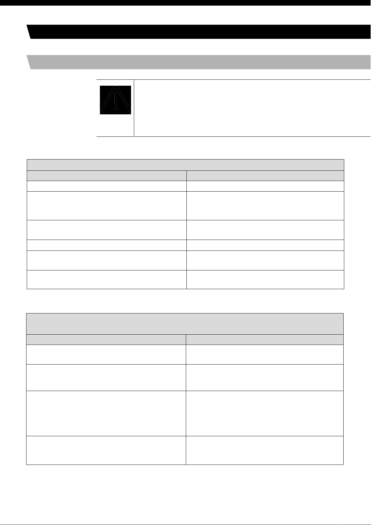
►Check the pump (see Tab. 9 to 12).
Pump produces no flow
Cause Fault remedy
No voltage in the power source ►Check room fuse and switch on if necessary.
Thermal switch has operated following to over-heating.
►Disconnect pump from mains.
►Allow pump to cool.
►Trace cause of over-heating and eliminate it.
Connections or lines blocked. ►Check connections and lines.
►Remove blockage.
External valve is closed or filter is clogged. ►Check external valves and filters.
Condensate has collected in pump head. ►Detach the condensate source from the pump.
►Flush pump (see chapter 8.2.1).
Diaphragm or valve plates/sealings (valve plates)
are worn.
► Replace diaphragm and valve plates/sealings
(valve plates) (see chapter 8.3).
9 .Troubleshooting
Flow rate, pressure or vacuum too low
The pump does not achieve the output specified in the Technical data or the data sheet.
Cause Fault remedy
Condensate has collected in pump head. ►Detach the condensate source from the pump.
►Flush pump (see chapter 8.2.1).
There is gauge pressure on pressure side and at
the same time vacuum or a pressure above
atmospheric pressure on suction side.
►Change the pressure conditions.
Pneumatic lines or connection parts have an
insufficient cross section.
►Disconnect pump from system to determine
output values.
►Eliminate throttling (e.g. valve) if necessary.
►Use lines or connection parts with larger cross
section if necessary.
Leaks occur on connections, lines
or pump head.
►Check that tubes sit correctly on hose nozzles.
►Replace leaky tubes.
►Eliminate leaks.
Table. 9
17

SLS Lab Basics Mini Vacuum Pumps SLS2600/2602
Flow rate, pressure or vacuum too low
The pump does not achieve the output specified in the Technical data or the data sheet.
Cause Fault remedy
Connections or lines completely or
partially jammed.
►Check connections and lines.
►Remove the jamming parts and particles.
Head parts are soiled. ►Change the pressure conditions.
Diaphragm or valve plates/sealings (valve plates)
are worn.
►Replace diaphragm and valve plates/sealings,
(valve plates) (see chapter 8.3).
After diaphragm and valve plates/sealings (valve
plates) have been replaced.
►Check that the spacers have been replaced onto
the diaphragm screw thread.
►Check head connection and hose connections
for leaks.
►Possibly carefully tighten the outer screws of
the top plate crosswise.
Table. 10
18
Pump is switched on, but does not run, the on/off-switch on the pump is not lit
Cause Fault remedy
Pump is not connected with the power source. ►Connect pump to mains power.
No voltage in the power source. ►Check room fuse and switch on if necessary.
Fuse in the pump is defective. ►Remove pump’s mains plug from the socket.
►Loosen marked lid on underside of the pump.
►Select and replace suitable fuse (see chapter 4).
Table. 11
Pump is switched on, but does not run, the on/off-switch on the pump is lit
Cause Fault remedy
The thermal switch has opened due to overheating
►Remove pump´s mains plug from the socket.
►Allow pump to cool.
►Trace cause of over-heating and eliminate it.
Table. 12
SLS Lab Basics Mini Vacuum Pumps SLS2600/2602
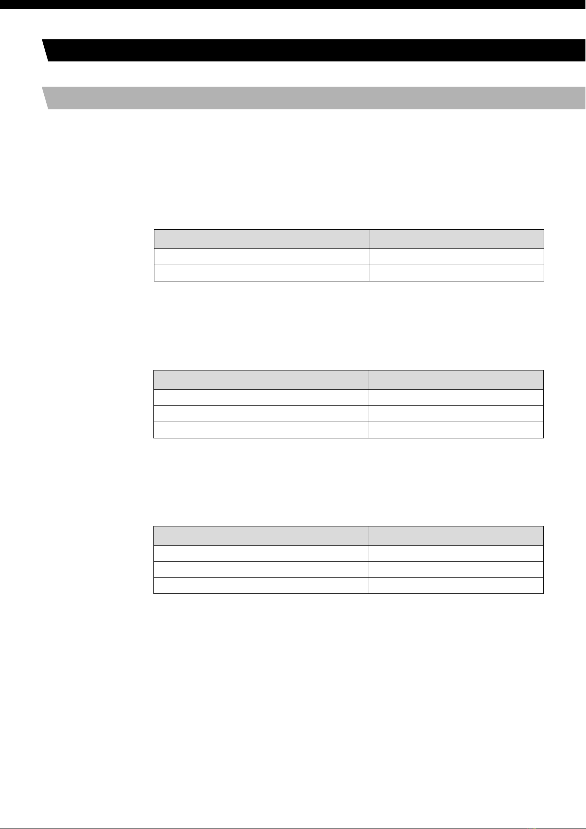
10 . Spare parts and accessories
10.1. Spare parts
A Service Set contains all spare parts needed for one complete service.
►For pump range SLS2600/2602:
1 diaphragm, 2 valve plates/sealings.
Service Set for pump type: Order-No.:
SLS2600 043241
SLS2602 043242
Table. 13
Fuses
Each pump contains two fuses.
Pump range Order-No. fuse (1 piece)
SLS2600/2602 – 230V 025250
SLS2600/2602 – 115V 020085
SLS2600/2602 – 100V 020085
Table. 14
10.1. Accessories
Description Order-No.:
Silencer 000345
Filter 000346
Hose connector PVDF 025671
Table. 15
19

United Kingdom:
International:
Northern Ireland:
Republic of Ireland:
SLS Lab Basics
Mini Vacuum Pumps
Our Knowledge + Your Equipment = Service Tailored to You
Clarity in Servicing
Our service options:
Fault Find & Fix
With service prices starting at just £17.95,
the Fault Find & Fix Service will collect your
benchtop laboratory equipment, diagnose the
faults and repair them
Service Contracts
For business critical equipment where
continual operation is a priority, we offer
annual preventative maintenance contracts
Pipette Servicing
As an independent channel partner to a vast
range of liquid handling solutions, we offer
pipette servicing solutions for an extensive
range of brands
On-Site Repairs
For an agreed fee, the SLS Service Centre
will dispatch an engineer to your site to
evaluate your equipment and diagnose
potential repairs.
To book your service or for further information
please contact us…
Email:
servicecentr[email protected]
Telephone:
0115 977 5075
Website:
www.scientificlabs.co.uk/servicecentre
SERVICE
CENTRE
Website: www.scientificlabs.co.uk/servicecentre
Clarity in Servicing
Our service options:
Plan ahead for fewer disruptions and greater productivity.
Keep your lab running smoothly with the SLS Service Centre.
To book your service or for further information
please contact us…
Email:
Telephone:
0115 977 5075
Repair
Calibration
Spare Parts
Training
Validation
Maintenance
Qualification
Installation
Project Design
& Management
Project Design & Management
Installation
Qualification
Repair
Maintenance
Calibration
Validation
Spare Parts
Training
SERVICE
CENTRE
Scientific Laboratory Supplies Ltd
Wilford Industrial Estate
Ruddington Lane
Wilford
Nottingham
NG11 7EP
This manual suits for next models
1
Table of contents
Popular Water Pump manuals by other brands


Agilent Technologies
Agilent Technologies VS PD03 installation instructions

Ulvac
Ulvac MBS-053 instruction manual

Metabo
Metabo HWA 5500 M Original operating instructions

pumpa
pumpa BLUE LINE 3SKM 100 Translation of the original instruction manual

Simplex
Simplex PAM Series Operating & maintenance instructions

ITT
ITT Goulds Pumps AF Installation, operation and maintenance instructions