Slycma RHEA 160 2P Datasheet

Réf. 2640100 (Version française Indice A)
02/10/2017
Installation,
commissioning and servicing manual
Full-Front,
Reduced and without frame
RHEA 160 2P/3P/4P

RHEA 160 2P/3P/4P
Index
2/67
Réf.
2640100_A
1
Description..............................................................................................................4
2
Safety.......................................................................................................................5
2.1
EC compliance statement « Universal locking device ».................................... 5
2.2
Standards and regulations................................................................................ 5
2.3
Symbols............................................................................................................ 5
2.4
Safety instructions for servicing operations ...................................................... 5
3
Equipment receipt ..................................................................................................6
3.1
Packaging......................................................................................................... 6
3.2
Storage instructions.......................................................................................... 9
3.3
Maintenance instructions.................................................................................. 9
4
Installation.............................................................................................................10
4.1
Assembling the doorframe.............................................................................. 10
4.1.1
Assembling the threshold ........................................................................ 10
4.1.2
Assembling of the posts on the threshold................................................ 11
4.1.2.1
Intumescent joints assembling (EA)..................................................... 11
4.1.1
Assembling the threshold jambs.............................................................. 13
4.1.2
Assembling the lintel (FC/HR) ................................................................. 14
4.1.3
Assembling the side attachments of the jambs (FC/HR) ......................... 15
4.1.4
Assembling the jambs and the lintel (EA)................................................ 16
4.1.5
Assembling the jamb extensions (as required)........................................ 18
4.2
Assembly of the drive mechanism.................................................................. 19
4.2.1
Position the securing brackets................................................................. 19
4.2.2
Installing the mechanism......................................................................... 20
4.2.3
Check of manual unlocking operation...................................................... 21
4.2.4
Mounting the mechanism on the bay and the jambs ............................... 22
4.3
Assembling the panels and the guide shoes (assembly represented 2P sheet
metal) ........................................................................................................................ 23
4.4
Assembling the panels and the guide shoes (assembly represented 2 glazed
panels)....................................................................................................................... 24
4.5
Adjusting the panels and the guide shoes...................................................... 25
4.6
Assembling the counterweight (3PSO / 2PSO)............................................... 28
4.7 Unlocking the lowest level (3PSO/2PSO)....................................................... 29
4.8
Unlocking the lowest level (4PCO/2PCO)....................................................... 30
4.9
Assembling the toe guard............................................................................... 31
4.10
Adjustments.................................................................................................... 32
4.10.1
Adjustment of the locking device (as required)........................................ 32
4.10.2
Adjustment of the trolleys (as required)................................................... 34
4.10.3
Adjustment of the kicking-rollers.............................................................. 37
4.10.4
Adjustment of the landing door/lift door relationship................................ 38
5
Connection............................................................................................................39
6
Commissioning.....................................................................................................40
7
Maintenance..........................................................................................................43
7.1
Preventive maintenance ................................................................................. 43
7.2
Corrective maintenance.................................................................................. 47

RHEA 160 2P/3P/4P
Index
Réf.
2640100_A 3/67
7.2.1
Replacing the hauling cables (3PSO) .....................................................47
7.2.1.1
Remove the counterweight (see § 4.5 page 22)...................................47
7.2.1.2
Removing the hauling cable slow trolley :.............................................47
7.2.1.3
Removing the haulage cable intermediate trolley.................................48
7.2.1.4
Installing the hauling cable slow trolley.................................................48
7.2.1.5
Installing the haulage cable intermediate trolley...................................48
7.2.1.6
Resuming the adjustment of the trolleys (see § Erreur ! Source du renvoi
introuvable. page Erreur ! Signet non défini.)......................................................48
7.2.1.7
Replace the counterweight (see § 4.5 page Erreur ! Signet non défini.)48
7.2.2
Replacing the hauling cables (2VOL)......................................................50
7.2.3
Replacing the hauling cables (4VOC)......................................................51
7.2.3.1
Unhooking return spring .......................................................................51
7.2.3.2
Removal of the left or right slow trolley hauling cable...........................51
7.2.3.3
Removal of the inversion hauling cable................................................52
7.2.3.4
Installation of the left or right slow trolley hauling cable........................52
7.2.3.5
Assembly of the inversion hauling cable...............................................52
7.2.3.6
Trolleys adjustment ..............................................................................53
7.2.3.7
7.2.1.7 Repositioning the return spring.................................................53
7.2.4
Replacing the inversion hauling cable......................................................54
7.2.4.1
Unfastening the return spring ...............................................................54
7.2.4.2
Removal of the inversion hauling cable................................................54
7.2.4.3
Assembly of the inversion hauling cable...............................................54
7.2.4.4
Trolley adjustment................................................................................54
7.2.4.5
Repositioning the return spring.............................................................54
7.2.5
Replacing the locking sub-system............................................................55
7.2.6
Replacing the lock hook system...............................................................56
7.2.7
Replacing the rollers (3PSO)....................................................................57
7.2.8
Replacing the rollers (2PSO)....................................................................59
7.2.9
Replacing the rollers (4PCO) ...................................................................62
7.2.10
Replacing the rollers (2PCO) ...................................................................64
7.2.11
Replacing the trolley stopper....................................................................66

1
RHEA 160 2P/3P/4P
Description
4/67
Réf.
2640100_A
1 Description
This manual describes all operations associated with the installation, setting and
maintenance of Rhea 2 and 4 panel central opening (CO) and 2 and 3 panel side
opening (SO) landing.
This manual concerns the following types of door:
Full-front entrance (FC)
Reduced frame (HR).
Without frame entrance (EA)
The Rhea 3P and 2P landing doors include the following options:
Car door locking device (VPC)
Joint covers (FC / HR).
EN 81-21 (remote magnetic switch) (FC / HR)
The Rhea 4P landing doors include the following options:
Joint covers (FC / HR).
EN 81-21 (remote magnetic switch) (FC / HR)

RHEA 160 2P/3P/4P
2
Safety
Réf.
2640100_A 5/67
2 Safety
2.1 EC compliance statement « Universal locking device »
(Available on www.slycma.com).
2.2 Standards and regulations
The equipment described herein complies with the following standards:
EN 81-20 / 50.
EN 81-58 (E120).
EN 81-21.
EN 82-212/312.
XPP 82-511/611.
2.3 Symbols
Imperative
Instruction that draws the attention of the reader on the injury or death hazards the
user should be aware of. These instructions concern safety at work.
Careful
Instruction that draws the attention of the reader on equipment damage hazards.
These instructions concern the quality of work.
2.4 Safety instructions for servicing operations
Imperative
Maintenance operations are to be carried out by trained and competent personnel.
Required safety equipment:
Helmet.
Gloves.
Safety shoes.
Harness.

3
RHEA 160 2P/3P/4P
Equipment receipt
6/67
Réf.
2640100_A
3 Equipment receipt
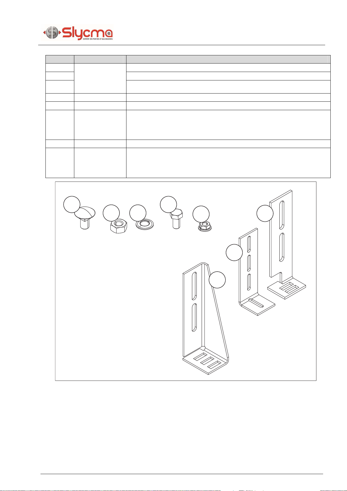
3.1 Packaging
Rep. Qty. Designation
1
8
4P
6
3P
4
2P
Panel attachment
2Axis for the guide shoe
3Guide shoe
4Domed-head screw/square collar M8 x 16
5RHC screw with M8 base x 12
6Slotted nut M8
7Mid-size flat washer MU 8 x 18
816
4P
12
3P
8
2P Slotted nut M8
91 Rubber stopper (4P/2P)
Rep. Qty. Designation
10 1
FC/HR
4
EA Slotted nut M 5
11 RHC screw M5 x 12
12 21 RHC screw with M6 base x 12 (FC/HR)
13 20 RHC screw with M6 base x 10 (EA)
14 12
FC/HR
5
EA BN 992 ST metal screw screw 4.2 x 6.5
15 10 Self-tapping screw M5x10 (EA)
1
234
5
6789
10 11 12 13 14 15
RHEA 160 2P/3P/4P
3
Equipment receipt
Réf.
2640100_A 7/67
Rep. Qty. Designation
16 5
6
2P SO
(CO 1150 to
1300)
Square collar screw M10 x 20
17 HM10 nut
18 JZC10 washer
19 4 HM screw 8 x 16 (FC/HR)
20 4 Slotted nut M8 (FC/HR)
21 5
6
2P SO
(CO 1150 to
1300)
Low and High Bracket EA)
22 4 Side angle bracket (FC/HR)
23 5
6
2P SO
(CO 1150 to
1300)
Low and High Bracket (FC/HR)
16 19
1817 20 23
22
21

3
RHEA 160 2P/3P/4P
Equipment receipt
8/67
Réf.
2640100_A
Rep. Qty. Designation Rep. Qty. Designation
1 1 Lintel fitted with unlocking device 7 4
4P
3
3P
2
2P Panels
2 1 Mechanical device
3 1 Counterweight lot
(3V/2V OL)
4 1 Slam post
(3P/2P SO)
8 1
SO
2
CO Bunch post
5 1 Counterweight protection metal
sheeting
(3P/2P SO)
6 1 Threshold lot 9 1 Toe guard
10 9 ou
11 m Intumescent seal 30x2
(EA)
12
3
10
4
5
78
8
8
69
1
FC/HR
EA
FC
HR
EA

RHEA 160 2P/3P/4P
3
Equipment receipt
Réf.
2640100_A 9/67
3.2 Storage instructions
The delivered equipment is to be stored in its packaging and kept away from bad
weather.
Imperative
Do not bunch more than two parcels one on top of the other.
3.3 Maintenance instructions
The equipment is delivered on pallet-mounted boxes.
The maximum weight of a parcel is of 200 kg..

4
RHEA 160 2P/3P/4P
Installation
10/67
Réf.
2640100_A
4 Installation
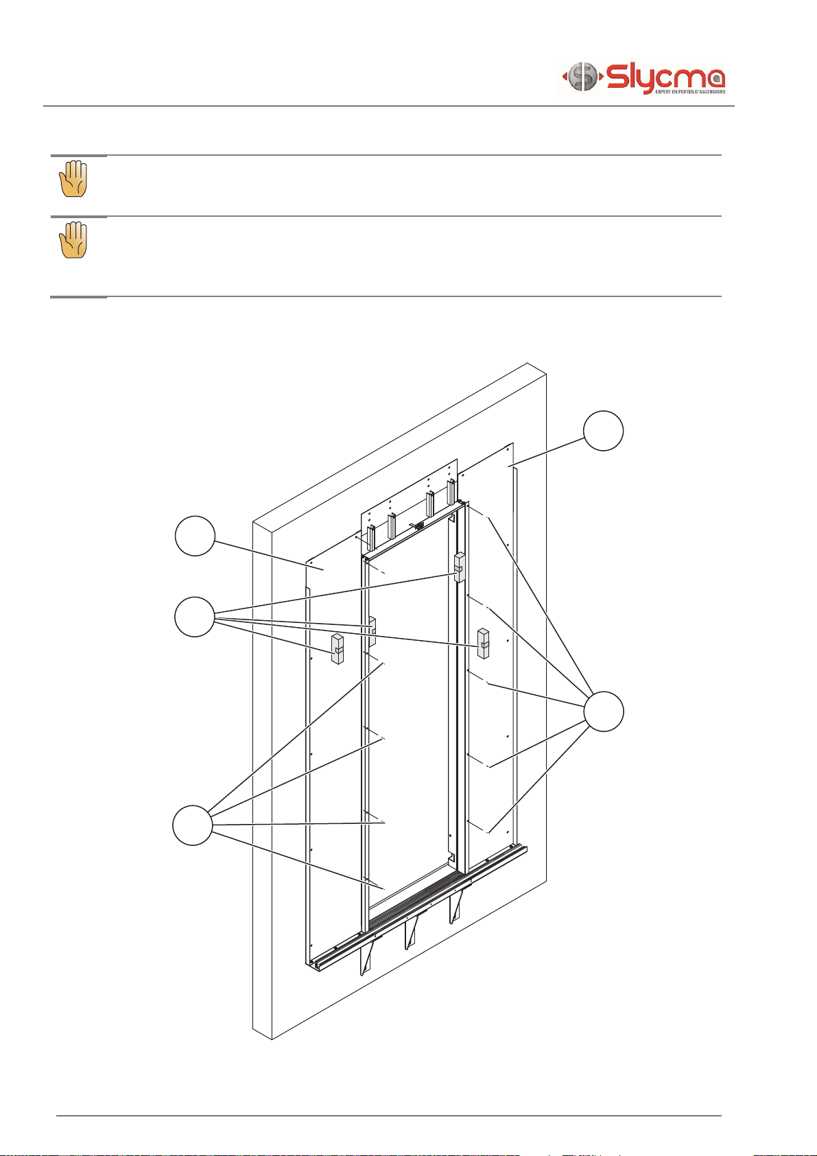
4.1 Assembling the doorframe
4.1.1 Assembling the threshold
Position the dome-head/square collar screw M10x20 (1),
JZC-10 washers (2), M10 nuts (3) on each of the three securing brackets (4).
Place the three brackets on the threshold.
FC/HR : Position and assemble the threshold elements to achieve the required
overhang in shaft (P).
EA : Align the concrete threshold or position it against the frame of the swing door
(6) when the door is projecting
Attach the pegs (5) (optional)
P
1
2
3
4
5
1
2
3
4
5
6
EA
FC/HR
FC/HR
EA
RHEA 160 2P/3P/4P
4
Installation
Réf.
2640100_A 11/67
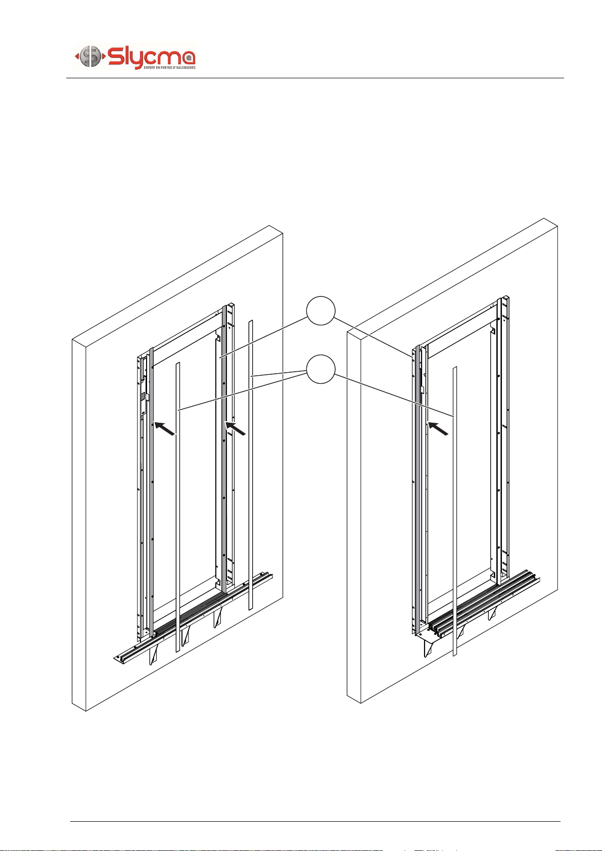
4.1.2 Assembling of the posts on the threshold
4.1.2.1 Intumescent joints assembling (EA)
Glue 2 intumescent joints (1) on the inside returns of the frame of the swinging door
(2).
Door SO : Glue 1 intumescent seal on the outside return of the swinging door
frame (2) on the slam side.
2
1
SO

4
RHEA 160 2P/3P/4P
Installation
12/67
Réf.
2640100_A
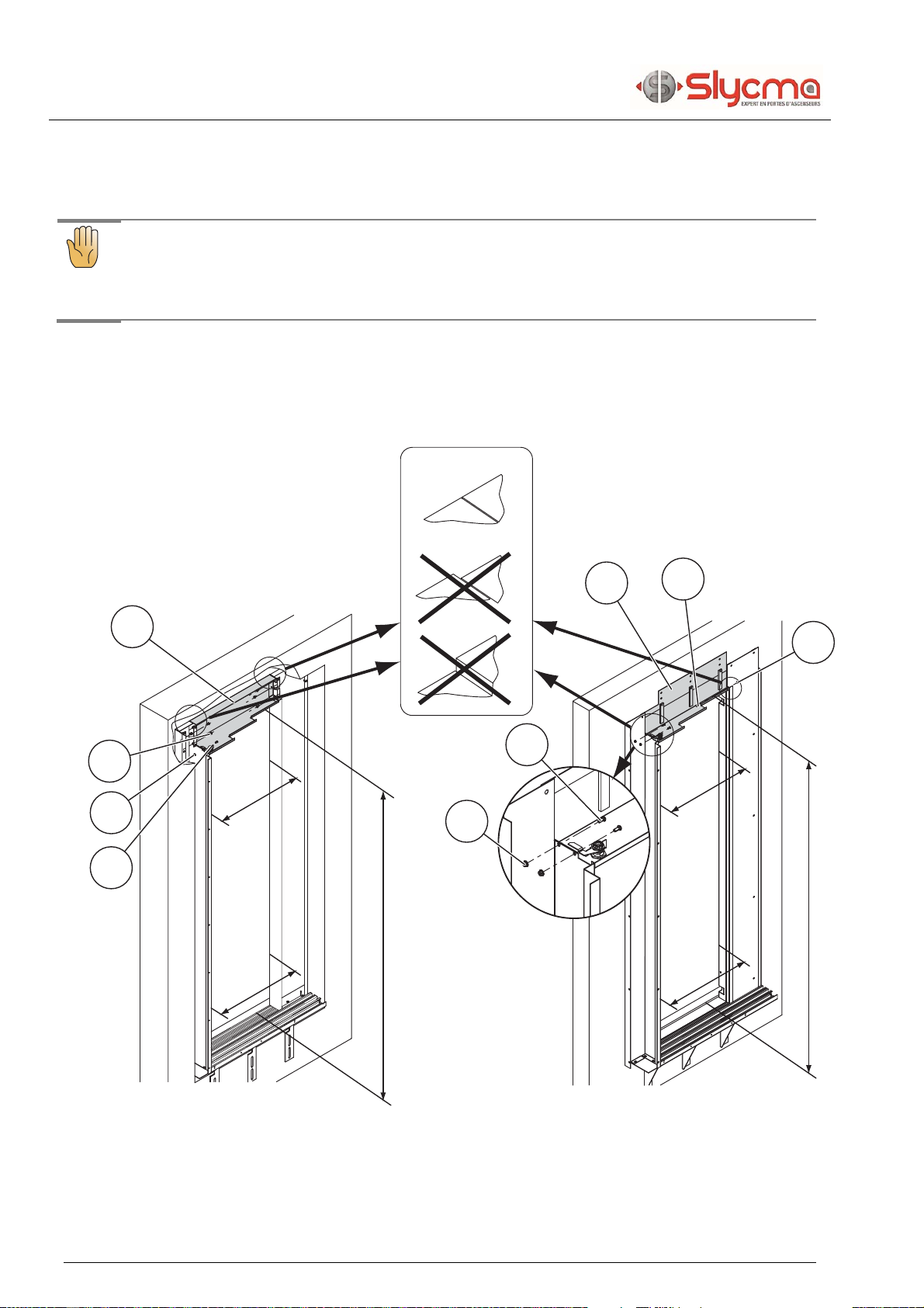
Glue 2 intumescent joints (1) on the landing door posts :
oPosition these 2 joints at (A = approx. 10 mm) outside the swinging door
frame (2).
The overhang of the swing door must be less than 30 mm. Otherwise plan the
installation of a plasterboard, calcium silicate or rockwool tape bonded to the
concrete to bring it back to 30 mm maximum.
2
1
A

RHEA 160 2P/3P/4P
4
Installation
Réf.
2640100_A 13/67
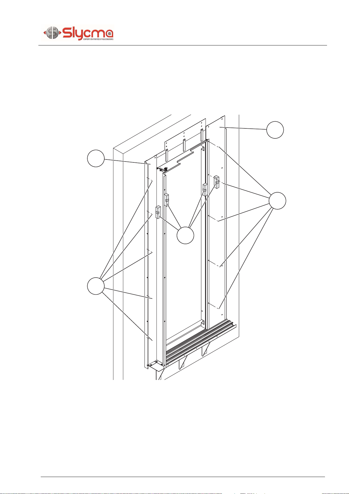
4.1.1 Assembling the threshold jambs
Position and assemble the posts (1) with the RHC screws with base (2).
oFC/HC : RHC with base M6X12.
oEA : RHC with base M6X10.
3
4
1
2
4
RHEA 160 2P/3P/4P
Installation
14/67
Réf.
2640100_A
4.1.2 Assembling the lintel (FC/HR)
Position the lintel (1).
Careful
Check clear opening (PL) and clear height HL).
Check the proper alignment of lintel and posts.
Position and assemble the lintel (1) :
oFC/HR : with the RHC screws with M6 base x 12 (2) and the RHC M5x12
screw (4) with the slotted nut M5 (3).
oEA : with the RHC M5x12 screws (4and the slotted nuts M5 (3).
OK
PL
PL
HL
PL
PL
HL
1
2
3
4
1
4
3
4
3
FC/HR
EA
FC/HR
EA
RHEA 160 2P/3P/4P
4
Installation
Réf.
2640100_A 15/67
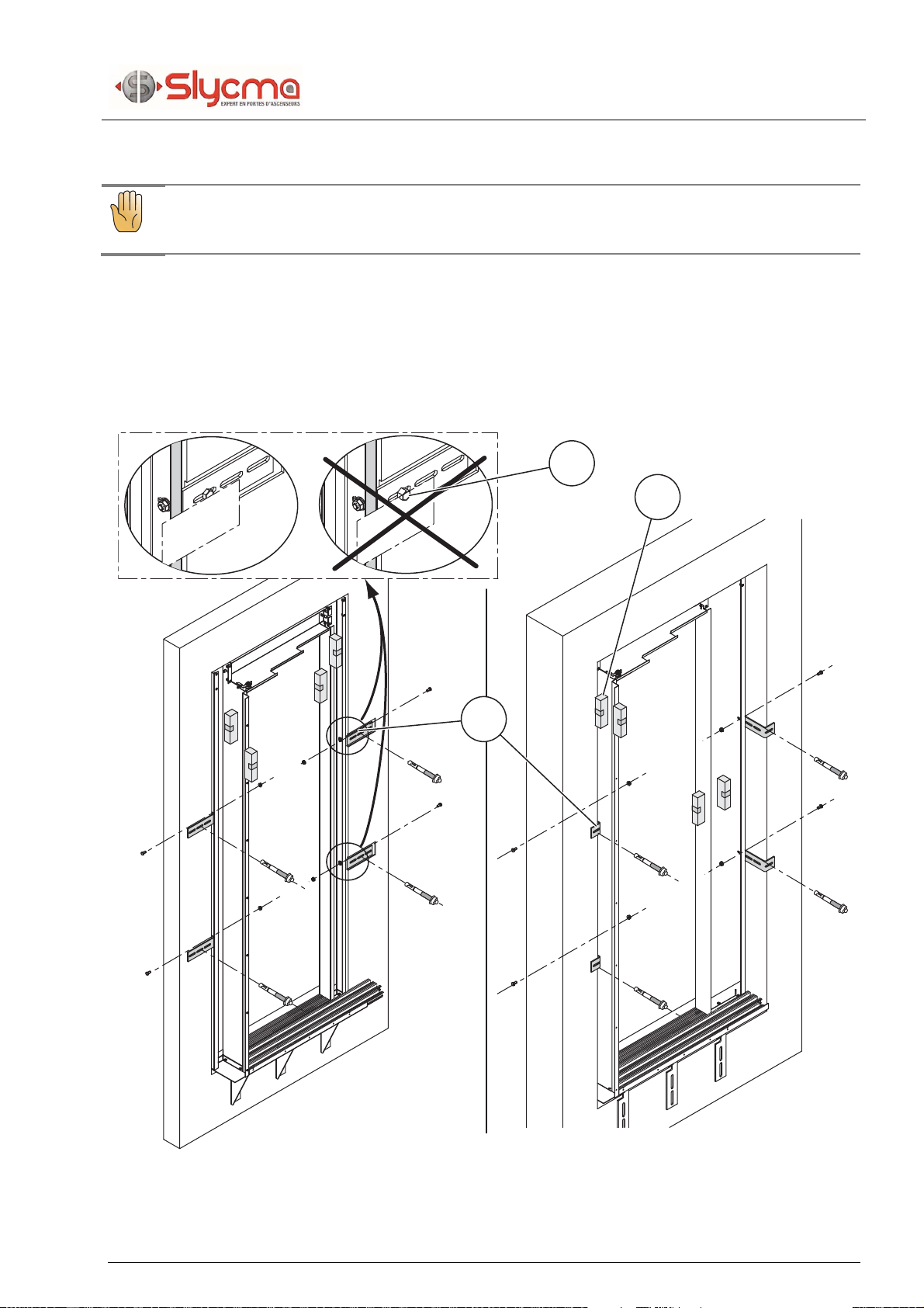
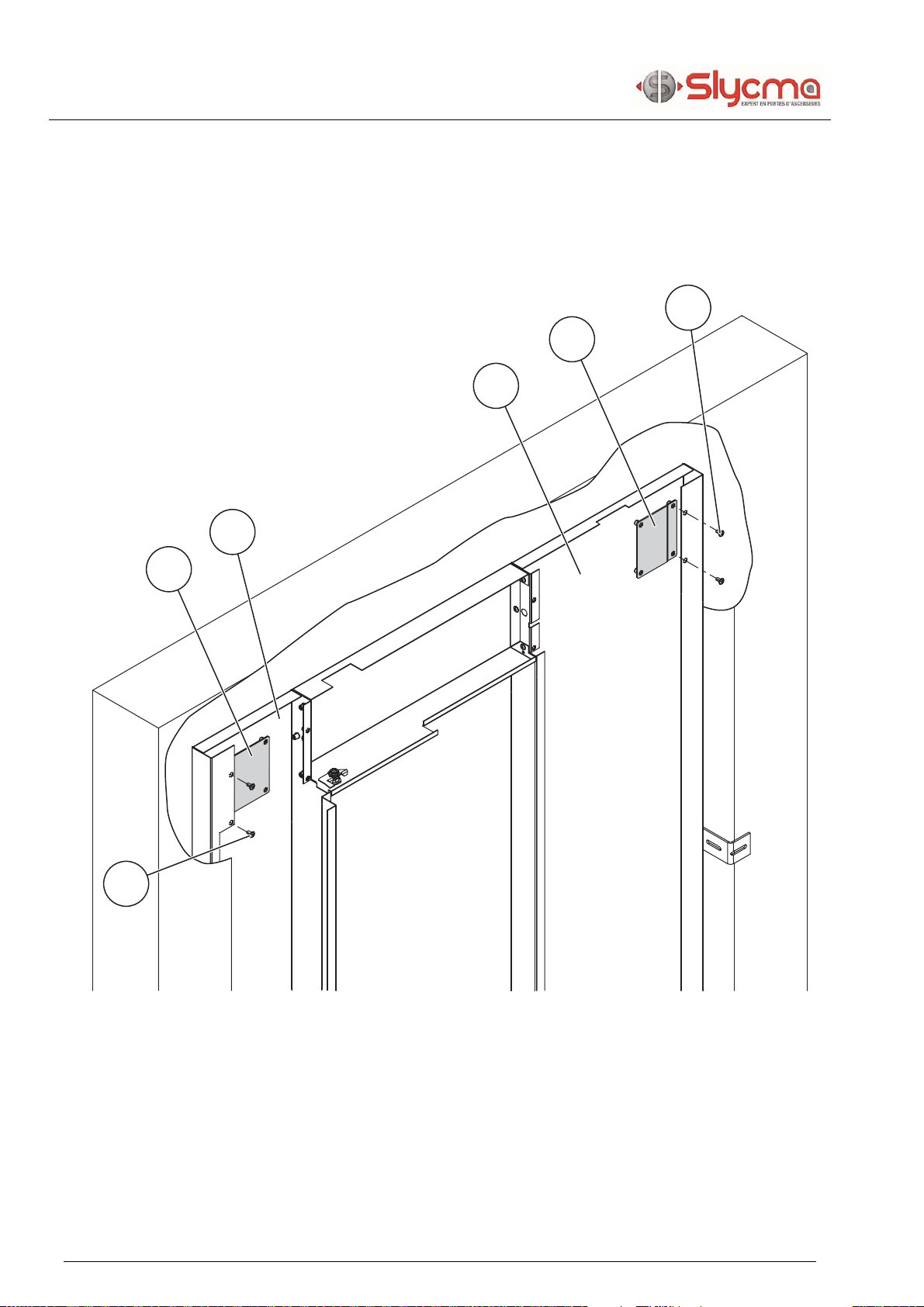
4.1.3 Assembling the side attachments of the jambs (FC/HR)
Careful
Check that the jambs are vertically mounted..
Position the brackets (3) according to the type of assembly (HR or FC).
Secure the brackets while making sure the jambs are vertical (2) (HM8X16 screws
and M8 nuts).
For reduced frame assembly, take care not to let the attachments (1) extend further
than the edge of the garage jamb.
OK
3
2
1
HR
FC
4
RHEA 160 2P/3P/4P
Installation
16/67
Réf.
2640100_A
4.1.4 Assembling the jambs and the lintel (EA)
Careful
Check that the jambs are vertically mounted (4).
Careful
In order to comply with fire prevention certification, the pediment and
jambs must be sealed.
Counter-drill (4.5) the posts (1).
Assembly the uprights (1) with 10 self-tapping screws M5x10 (2).
1
3
2
1
2
CO
RHEA 160 2P/3P/4P
4
Installation
Réf.
2640100_A 17/67
Counter-drill (4.5) the bunch posts (1).
Drill (4.5) the slam post (4) in line with the fold of the swing door.
Assembly the uprights (1) with 10 self-tapping screws M5x10 (2).
3
1
2
2
4
SO
4
RHEA 160 2P/3P/4P
Installation
18/67
Réf.
2640100_A
4.1.5 Assembling the jamb extensions (as required)
If the width of the closing jamb (2) is equal to or greater than 155 mm, attach the
extension (1) with RHC M6X12 attachment screws (5).
If the width of the garage jamb (3) is equal to or greater than PL/2 + 95 mm, attach
the extension (4) with RHC M6X12 attachment screws (5).
4
3
1
2
5
5
RHEA 160 2P/3P/4P
4
Installation
Réf.
2640100_A 19/67
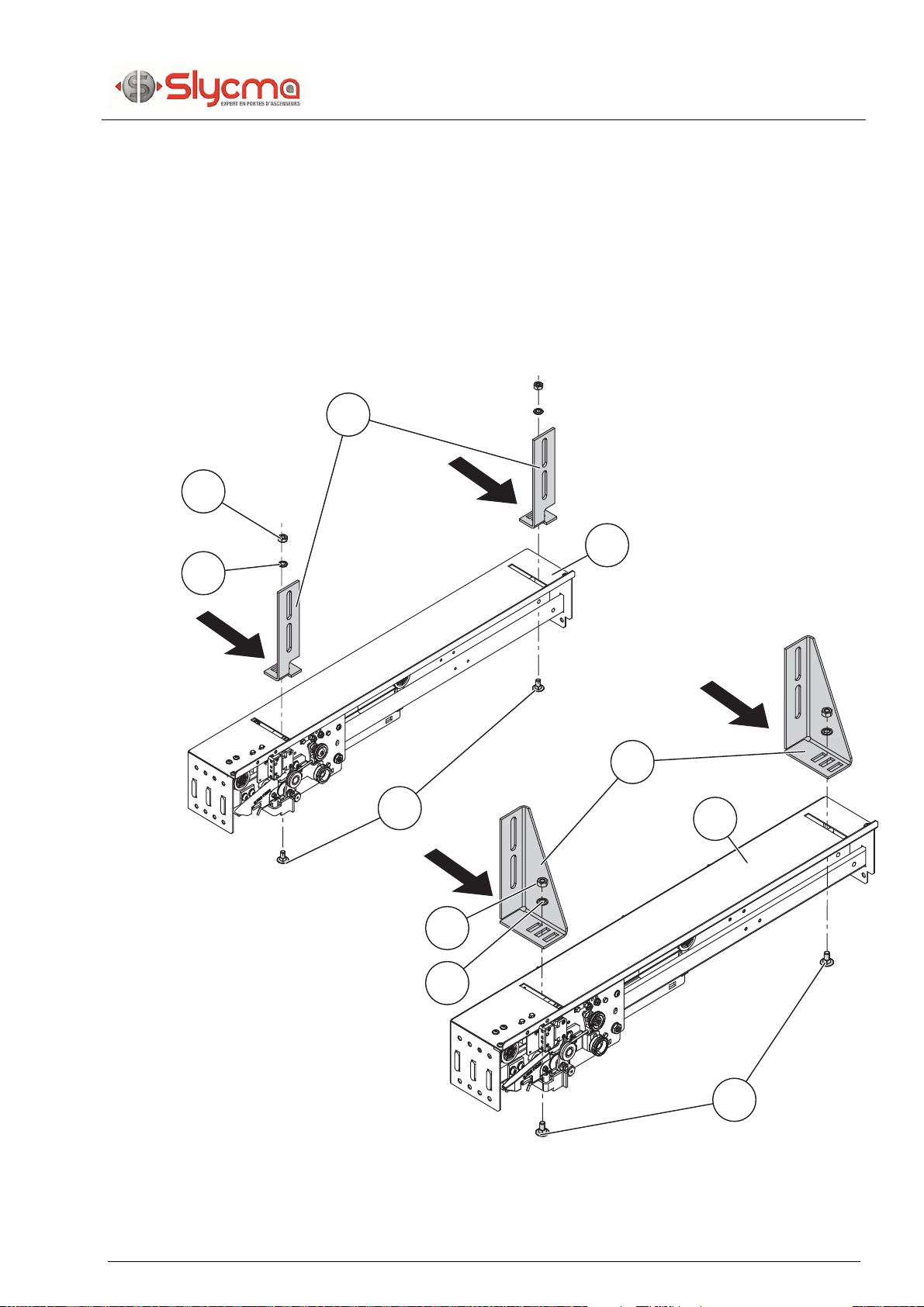
4.2 Assembly of the drive mechanism
4.2.1 Position the securing brackets
Position the securing brackets (4) with their dome-head/square collar screw
M10x20 (1), JZC-10 washers (2), M10 nuts (3) on the mechanism (5).
Do not tighten the attachments and push the brackets as far as possible towards
the shaft (folded side)
1
3
2
4
4
5
1
3
2
5
FC/HR
EA
4
RHEA 160 2P/3P/4P
Installation
20/67
Réf.
2640100_A
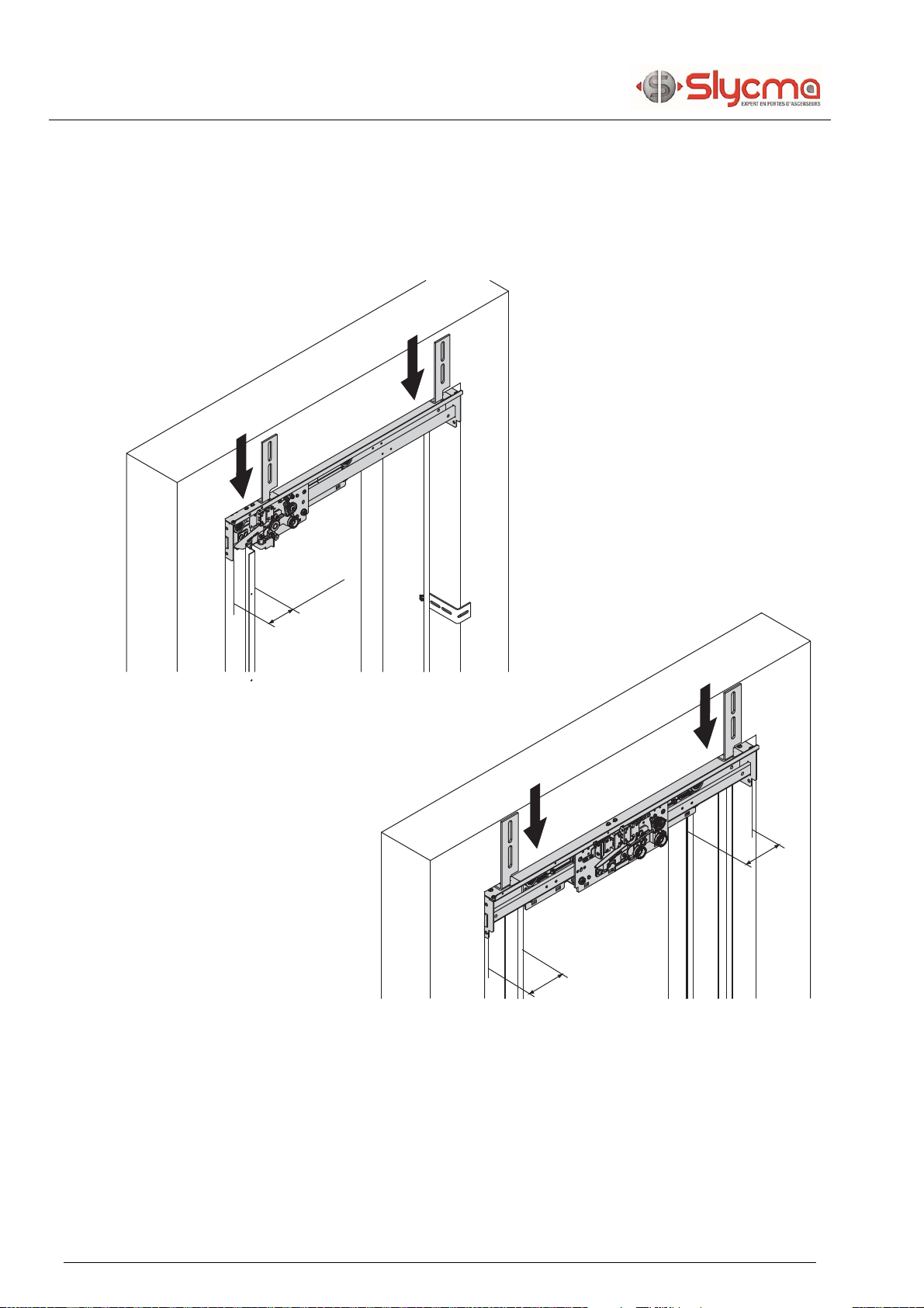
4.2.2 Installing the mechanism
SO : Position the mechanism so as to let it rest on the jambs and 110 mm from
the edge of the slam post.
CO : Position the mechanism in support on the uprights and center in the clear
opening.
=
=
110 mm
CO
SO
This manual suits for next models
2
Table of contents
Popular Door Opening System manuals by other brands


Prismatibro
Prismatibro Prisma Button 800 installation manual

BEA
BEA Gyrotech 1100 Wiring diagrams

Assa Abloy
Assa Abloy NORTON RIXSON 1600H Series installation instructions

SUGATSUNE
SUGATSUNE LAMP FD35EV installation manual

Sesamo
Sesamo Roto K3 Installation and Wiring

Falcon
Falcon 812L installation instructions

Nice
Nice SD-70-20 3 400 Instructions and warnings for installation

Assa Abloy
Assa Abloy SARGENT 281 Series installation instructions

Dormakaba
Dormakaba ED100 installation instructions

Backyard Chicken Coops
Backyard Chicken Coops Auto Door Opener Assembly instructions

SIMONSWERK
SIMONSWERK Anselmi AN 164 3D FVZ 12/38 manual

LCN
LCN 3130 Series installation instructions