Smappee EV Base User manual

English –Version 1.1 –March 2021
Smappee EV Wall
Business
Installation manual

Smappee EV Wall Business –Installation manual - English
2
Table of contents
1. Introduction ....................................................................................................3
2. Safety instructions...........................................................................................4
3. Models ............................................................................................................6
4. Components....................................................................................................7
5. Technical specifications...................................................................................8
6. Preparing the installation................................................................................9
7. Installation and activation.............................................................................12
8. Using the EV Wall Business ...........................................................................23
9. Declaration of conformity.............................................................................27

Smappee EV Wall Business –Installation manual - English
3
1. Introduction
Thank you for purchasing this Smappee EV Wall Business charging station for electric vehicles, the
smartest charging station for businesses.
This installation and user manual tells you how to install and use the Smappee EV Wall Business. We
advise you to read the contents of this manual carefully, to ensure a safe and proper installation and
enable you to use all the advanced features of this product to their full extent.
Support
Only qualified electricians or equivalent may install the Smappee EV Wall Business. If you have any
questions, please contact your service partner.
Please have the following information ready to hand to speed up the process: Article number and
serial number which you can find on the identification label of the charging station.
Should your local distributor be unable to help you, or you have a suggestion for us, you can contact
Smappee at: support@smappee.com.
Smappee n.v.
Evolis 104
8530 Harelbeke
Belgium

Smappee EV Wall Business –Installation manual - English
4
2. Safety instructions
Safety warning
Fully read and follow the safety instructions below before you install, service or use your Smappee
EV Wall Business. The installer must ensure that the charging station is installed in accordance with
the relevant national and local regulations.
Carrying out activities on this charging station without the relevant knowledge and qualifications can
lead to serious accidents and death. Only carry out tasks for which you are qualified and have been
fully instructed.
Incorrect installation, repairs or modifications can result in danger to the user and may void the
warranty and liability.
Safety precautions
CAUTION: Risk of electric shock.
CAUTION: Refer to the accompanying documentation whenever you see this symbol.
Please observe the following safety precautions to avoid potential electric shock, fire, or personal
injury:
•Use this charging station only for its intended purpose.
•Switch off electrical power supply to your charging station before installation or maintenance
work.
•Do not use the charging station if damaged / defective.
•Do not immerse the charging station in water or any other liquids.
•Do not expose the charging station to heat, flame or extreme cold.
•Do not attempt to open, repair, or service any parts. Contact Smappee or your service partner
for further information.
•Only use the charging station under the specified operating conditions.
•Do not allow children to operate a charging station.
•When a charging station is in use, adult supervision of any children present is required.
•While charging the charging cable must be completely unwound and connected to the electric
car without overlapping loops. This to avoid the risk of overheating the charging cable.
Maintenance
•Observe the maintenance schedule.
•Clean the outside only with a dry, clean cloth.
•Do not use abrasive agents or solvents.

Smappee EV Wall Business –Installation manual - English
5
Keeping order
•After charging, store the charging cable properly so it does not present a tripping hazard.
•Make sure the charging cable cannot become damaged (kinked, compressed or driven over).
•Do not place any objects on the charging station.
Transport and storage
•Disconnect electrical power supply before removing the charging station for storage or
relocation.
•Only transport and store the charging station in its original packaging. No liability for damage
incurred will be accepted if the charging station is transported in non-standard packaging.
•Store the charging station in a dry environment within the temperature range specified in the
technical specifications.

Smappee EV Wall Business –Installation manual - English
6
3. Models
Article no.
EAN
Description
EVWB-332-BR-E-W
5425036932159
EV Wall Business White 3-Phase 22 kW Socket
EVWB-332-BR-E-B
5425036932166
EV Wall Business Black 3-Phase 22 kW Socket
EVWB-332-C2R-E-W
5425036932197
EV Wall Business White 3-Phase 22 kW Type 2 cable
2,5m
EVWB-332-C2R-E-B
5425036932203
EV Wall Business Black 3-Phase 22 kW Type 2 cable
2,5m
EVWB-332-C8R-E-W
5425036932234
EV Wall Business White 3-Phase 22 kW Type 2 cable
8m
EVWB-332-C8R-E-B
5425036932241
EV Wall Business Black 3-Phase 22 kW Type 2 cable
8m

Smappee EV Wall Business –Installation manual - English
7
4. Components
Components included
1. 1 x Smappee EV Wall Business
2. 1 x EV Wall mounting plate
3. 3 x Screws
4. 3 x Plugs
5. 3 x Small screws
Type 2 EV charging cable
In case of a fixed cable version the cable is supplied in a separate box.
1. 1 x 2.5 m or 8 m open-ended to type 2 EV charging cable
2. 1 x cable tie for strain relief
3. 8 m version: 1 x EV cable holder + 3 x screws + 3 x plugs
Identification label
The identification label of your charging station is located on the left inside of the EV Wall Business.
1. Manufacturer
2. Article number
3. Rating
4. QR code containing article number and serial number
5. Manufacturing date
6. Degree of protection
7. Serial number

Smappee EV Wall Business –Installation manual - English
8
5. Technical specifications
Feature
Description
Socket
Type 2 cable
Technical features
Charging capacity
Single or triple phase, 3.7 to 22 kW
Output power
1-phase or 3-phase, 230 V –400 V, 32 A
Charge mode
Mode 3 (IEC 61851)
Connection case
1 x Case B (Socket type 2)
1 x Case C (Fixed cable with
type 2 connector)
Integrated Residual Current
Monitor
Rated operating residual current detection : 6 mA DC / 30 mA AC
Metering
MID certified class B
Interfaces & Connectivity
Information status
RGB LED
Session activation
Plug and charge, Scan QR code, Swipe RFID card, Smart EV
schedules
Connectivity
Ethernet 100BASE-T
Communication protocol
OCPP 1.6 JSON
Certifications and Standards
Product certification
CE
Standards
IEC 61851-1 (2017)
Environment
Enclosure material
Steel (housing), aluminium (front plate)
Enclosure rating
IP54 / IK10
Enclosure standard colours
RAL9016 (star white) + RAL7021 (black grey)
Operating temperature
-25 °C to 60 °C
Storage temperature
-25 °C to 80 °C
Relative humidity
0 % - 95 %, non-condensing
Maximum installation altitude
0 –2.000 m
Physical properties
Dimensions
300 x 300 x 110 mm
Weight (excluding packaging)
6.2 kg
6.8 kg (2.5 m cable) or 9.8 kg (8
m cable)
Charging cable length
N/A
1 x 2.5 m or 1 x 8 m
Mounting method
Wall

Smappee EV Wall Business –Installation manual - English
9
6. Preparing the installation
The first step is to prepare the physical installation of the EV Wall Business as described in this
chapter.
Installation prerequisites
•Calculate the existing electrical load to find the maximum operating current for the charging
station installation. The Smappee EV Wall Business is equipped with 1 connector (socket or
fixed cable) which needs to be powered. Note that with the Smappee overload protection
functionality more charging stations or the total maximum operating current can be higher
than the physical installation allows.
•Determine the voltage drop over the distance from the power supply panel to the charging
station installation. The voltage drop must not exceed 5 %. It is advised that the maximum
voltage drop be 3 %. The maximum wire gauge that can be fitted is 10 mm². Local regulations
may be applicable and can vary depending upon the region or country.
•Obtain all necessary permits from the relevant local authority.
•Refer to local wiring regulations to select the conductor sizes and use only copper conductors.
•Make sure that the installation area of the charging station is adequate for usability and
ventilation purposes.
•Use the correct tools and provide sufficient material resources and protection measures.
•Make sure that there is a stable internet connection available for each EV Wall Business, via
ethernet cable.
Route power supply
•The appropriate wire gauge of the supply cable depends on the power rating and distance
between the meter cabinet and the charging station. The voltage drop must not exceed 5%. It
is advisable to have a maximum voltage drop of 3%. The maximum wire gauge that can be
fitted is 10 mm².
•Route the power supply cables to the position where the charging station will be installed
together with an Ethernet cable for the internet connection.
•Make sure that there is at least 30 cm cable available at the location of the EV Wall Business
to be able to connect it easily internally.
The power supply enters the station at the bottom of the housing.
The Ethernet cable used for the internet connection also enters the charging station via
the floor plate. Ensure that you attach the RJ-45 connector only after inserting the cable
into the EV Wall Business housing.

Smappee EV Wall Business –Installation manual - English
10
The maximum power rating for each connector is specified in the table below.
Power per connector
Connection
Input current
Output current
3.7 kW
1-phase
1 x 16 A
1 x 16 A
11 kW
3-phase
3 x 16 A
3 x 16 A
22 kW
3-phase
3 x 32 A
3 x 32 A
Route ethernet cable
The EV Wall Business requires a stable internet connection via Ethernet. An RJ-45 connector (not
supplied) should be attached to the end of the cable. Only attach the RJ-45 connector after inserting
the cable into the housing. The RJ-45 connector will not fit through the EV Wall Business’s cable
gland!
Prepare the mounting
All Smappee EV Wall Business types are designed to be mounted on a wall.
When positioning the EV Wall Business, take into account that the power supply cables and
communication cable are entering the housing at the bottom through cable glands. The central M32
cable gland is for the power supply, the M20 cable gland for the communication cable.

Smappee EV Wall Business –Installation manual - English
11
Tools (not included)
Screwdrivers
3 mm Hex screwdriver
7 mm socket wrench with extension bar
Multimeter and earth ground meter
Wire stripper and cutter.
Needle-nose pliers.
Ferrules crimper, for stranded power supply cables
Drill and rock drill diameter 10 mm.
Hammer
RJ45 crimping tool
Supplies (included)
3 x wall plugs and screws anchors (Ø 6 mm x 50 mm)
3 x M4 x 6 mm HEX screws
Supplies (not included)
CAT 5/6 ethernet cable and RJ45 connector for internet access.
Power supply cables
Ferrules (10 mm²), for stranded power supply cables
32 A circuit breaker
Smappee EV Wall Business –Installation manual - English
12
7. Installation and activation
This procedure describes the required steps for the physical installation of the EV Wall Business.
CAUTION: Make sure it is not possible to connect the electric current during
installation. Put up caution tape and warning signs to mark the work areas. Make sure
no unauthorised people can enter the work areas.
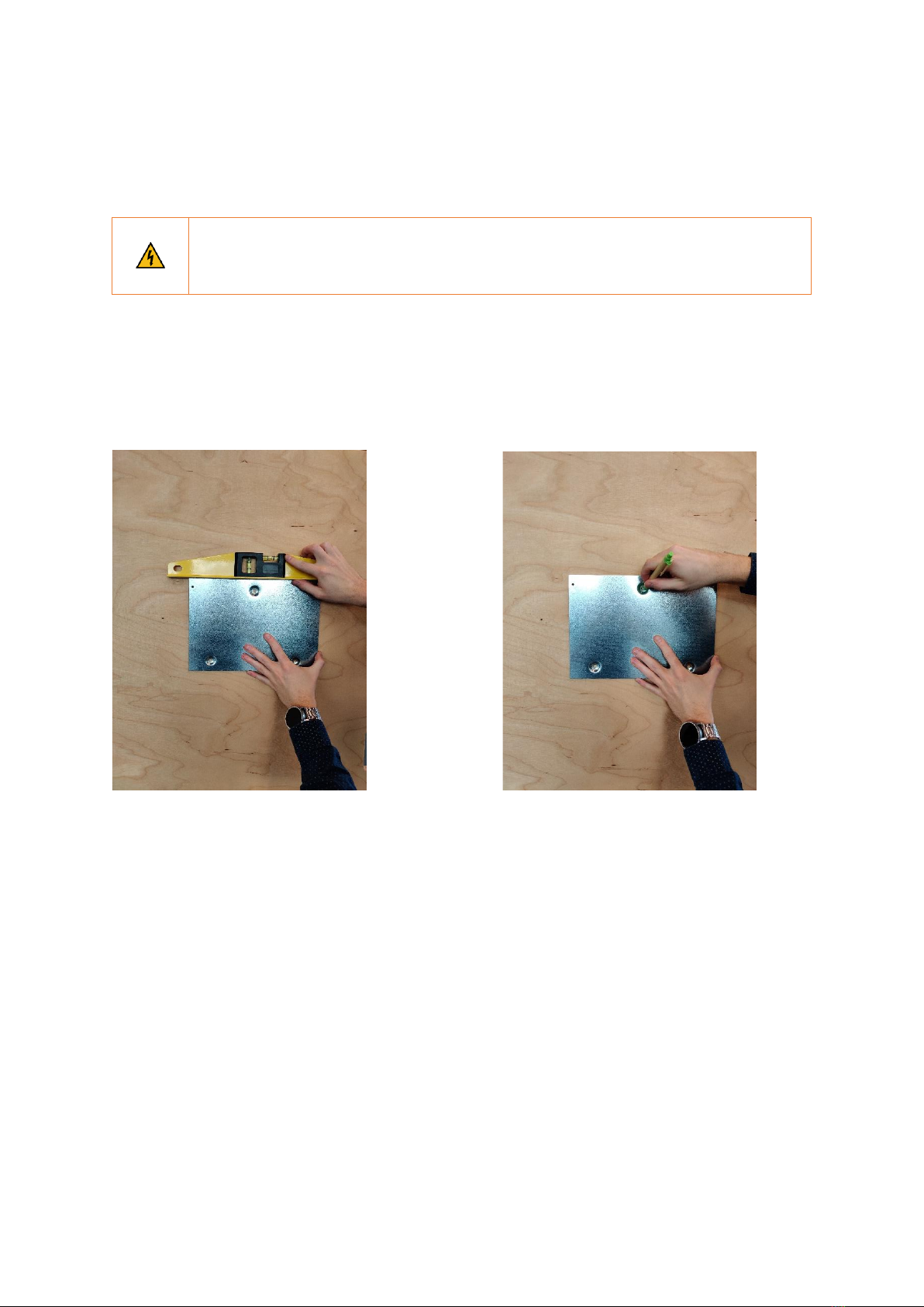
Place the mounting plate in position
a. Use the mounting plate to mark the position of the screws on the wall where the EV Wall
Business is to be positioned. Make sure the mounting plate is positioned with the 2 insert holes
on the bottom, as depicted below.

Smappee EV Wall Business –Installation manual - English
13
b. Drill 3 holes of 10 mm diameter through the slots to a depth of 50 mm. Insert the supplied wall
plugs into the holes.
c. Attach the mounting plate to the wall with the supplied screws.

Smappee EV Wall Business –Installation manual - English
14
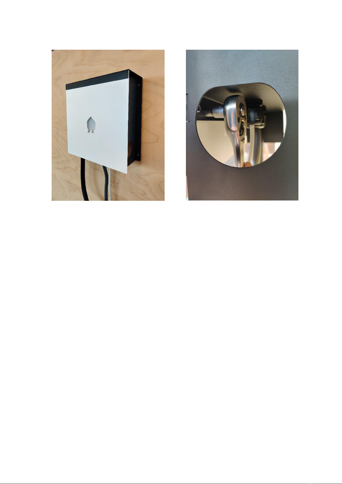
Place the EV Wall Business in position
a. Remove the front plate of the EV Wall Business and disconnect the communication cables. Safely
put aside the front plate to avoid damaging the PCB-board attached to it.
b. Attach the EV Wall Business housing to the mounting plate using the three supplied M4 x 6 mm
HEX screws.

Smappee EV Wall Business –Installation manual - English
15
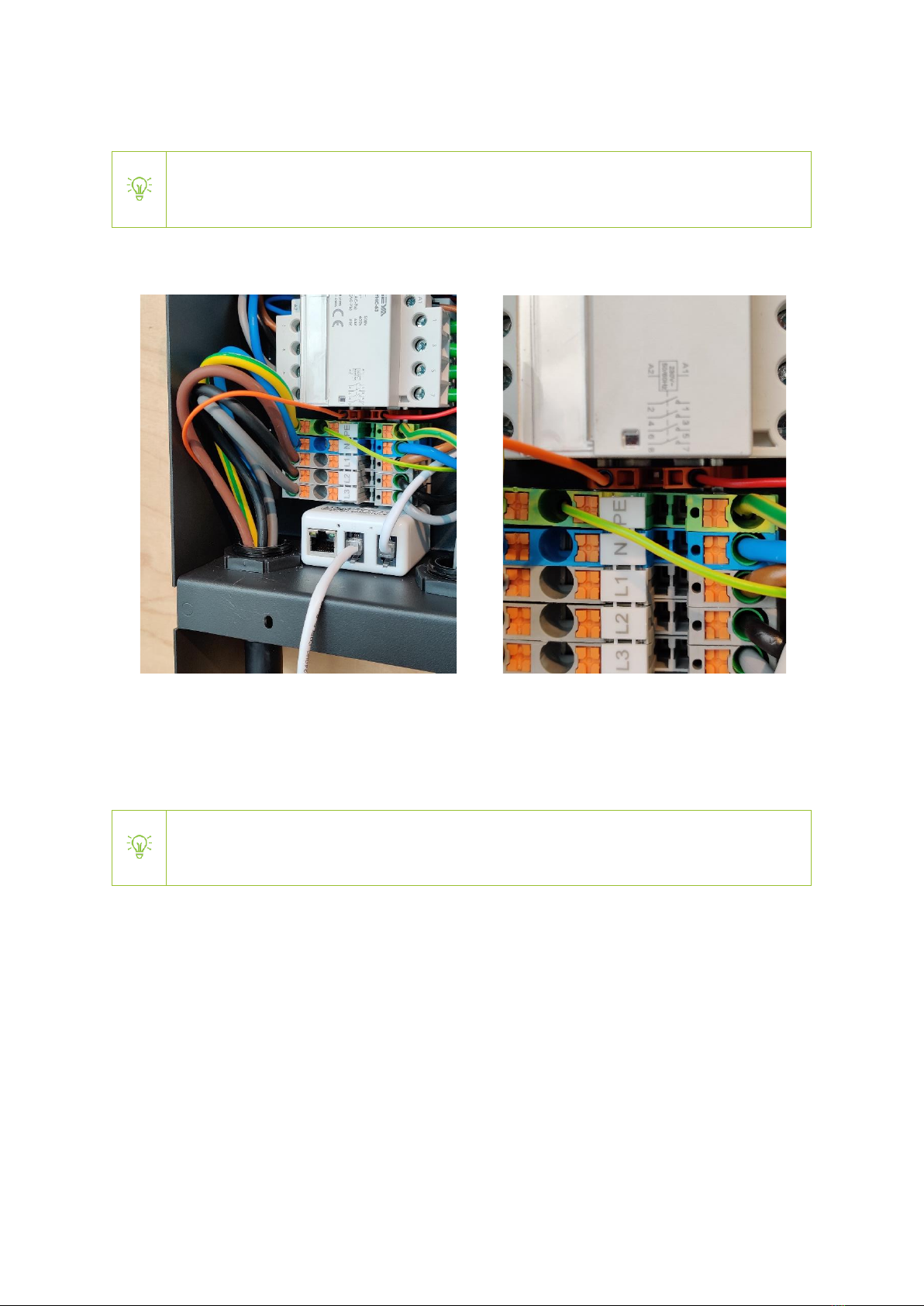
Power supply connection
a. Slide the power cable through the middle cable gland.
b. Cut the power supply cables to adequate length and add the ferrules to each conductor if
stranded cables are used.
c. Measure the resistance of the grounding circuit and make sure that it is within acceptable limits.
If necessary, install a grounding point closer to the charging station.
d. Connect each supply cable to the differential. The protective earth should be connected to the
terminal block. Tip: when using solid cables, use pliers to bend the cables into an ‘L’ shape
before connecting these to the differential.

Smappee EV Wall Business –Installation manual - English
16
Phase rotation
To avoid overloading the first phase with one-phase electric vehicles, phase rotation is
recommended. We recommend rotating the phases as shown in the table below.
Charging station
Phase mapping
EV Wall Business 1
L1 –L2 –L3 –N (as indicated on the differential)
EV Wall Business 2
L2 –L3 –L1 –N
EV Wall Business 3
L3 –L1 –L2 –N
And continue with this pattern for other EV Wall Business units.
When phase rotation is applied on a connector, adjust the configuration in the Smappee
Dashboard.
Smappee EV Wall Business –Installation manual - English
17
EV charging cable mounting (only fixed cable version)
This section is only relevant if the EV Wall Business comes with a fixed cable. If you have a
socket version, please continue to the next section.
a. Mount the fixed charging cable through the left M32 cable gland and mount the power supply
wires to the terminal block. Do not forget to connect the small orange CP data cable.
b. Mount the cable tie for strain relief on the charging cable after it enters the M32 cable gland.
c. For the 8 m version, a separate cable holder is supplied and can be mounted on the wall nearby
the EV Wall Business.
The length of the fixed cable can be shortened if required. Cut the cable to its required
length and add ferrules (not supplied).

Smappee EV Wall Business –Installation manual - English
18
IMPORTANT notes for 3P (3*230V) –Delta topology
When an EV Wall Business is installed in a residential installation with a 3P (3*230V) –Delta grid
connection, some additional requirements need to be taken into account. These guidelines have
nothing to do with the Smappee EV Wall Business architecture but linked to how the utility provides
the grid connection to the home.
Some EV-vehicles are not compatible with 3P (3*230V) grid connection due to a built-in security in
the EV. Contact your EV manufacturer for more information.
Context
There are 2 types of Delta connections that the grid operator can use in the low voltage cabinets and
is linked to type of transformer used there.
oDelta - Type 1: One of the phases in the low voltage cabin is connected to earth. The voltage
between ground & 1 of the phases is 0 volts.
oDelta - Type 2: None of the phases are connected to earth. The voltage between each phase
and earth is 130V.
The security feature that some EVs have is a voltage check the EV does between the phase that is
connected as neutral and the ground. If this is not 0 volts, the car won’t charge. The presence of this
security feature may vary for each manufacturer and for each model.
Guidelines
With these guidelines, you are able to determine what you need to do to make sure the EV Wall
Business can be charged.
Check prior to the EV Wall Business installation the type of Delta Topology by measuring the voltage
between the phases and ground.
•If 0 Volts => Type 1: all EV cars can charge using two phases. The phase that
provides 0V needs to be connected to the Neutral of the EV Wall Business power
supply.
•If 130V Volts (not 0V) => Type 2: if a specific EV is to be charged, check with the EV
manufacturer whether it is compatible with this setup. If a specific EV is not
compatible or multiple EV-types need to be charged, an isolation transformer needs
to be installed.

Smappee EV Wall Business –Installation manual - English
19
Closure
a. Attach an RJ45 connector to the Ethernet cable after feeding it through the cable gland. Plug it
into the Smappee Connect.
b. Mount the front plate into position by connecting the RJ10 cable to one of the B ports of the PCB
attached to the front plate.
Be careful to connect the RJ10 cable to one of the B ports. Do not connect it to the A port.
The Ethernet cable should be connected to the Smappee Connect, not to the PCB
attached to the front plate.
Smappee EV Wall Business –Installation manual - English
20
c. Mount and tighten the supplied M4 nuts
Other manuals for EV Base
7
This manual suits for next models
12
Table of contents
Other Smappee Automobile Accessories manuals

Smappee
Smappee Infinity User manual

Smappee
Smappee EVB-2332-B-E User manual

Smappee
Smappee EV Base User manual

Smappee
Smappee EV Base User manual

Smappee
Smappee EV One Home User manual

Smappee
Smappee EV One Home User manual

Smappee
Smappee EV One Home User manual

Smappee
Smappee EV Base Ultra User manual

Smappee
Smappee EV Base Ultra User manual


