Smappee EV Base Ultra User manual

English –Version 1.0 –July 2022
Smappee
EV Base Ultra
Installation manual

Smappee EV Base Ultra –Installation manual –English
2
Table of contents
1. Introduction ....................................................................................................3
2. Safety instructions...........................................................................................4
3. Models ............................................................................................................5
4. Components....................................................................................................6
5. Technical specifications...................................................................................8
6. Preparing the installation..............................................................................10
7. Installation and activation.............................................................................12
8. Maintenance .................................................................................................31
9. Using the EV Base Ultra.................................................................................32
10. Declaration of conformity.............................................................................36

Smappee EV Base Ultra –Installation manual –English
3
1. Introduction
Thank you for purchasing this Smappee EV Base Ultra charging station for electric vehicles, the
smartest DC charging station for businesses.
This installation and user manual tells you how to install and use the Smappee EV Base Ultra. We
advise you to read the contents of this manual carefully, to ensure a safe and proper installation and
enable you to use all the advanced features of this product to the full.
Support
Only qualified electricians or equivalent may install the Smappee EV Base Ultra. If you have any
questions, please contact your service partner.
Please have the following information ready to hand to speed up the process: Article number and
serial number which you can find on the identification label of the charging station.
Should your local distributor be unable to help you, or you have a suggestion for us, you can contact
Smappee at: support@smappee.com.
Smappee n.v.
Evolis 104
8530 Harelbeke
Belgium

Smappee EV Base Ultra –Installation manual –English
4
2. Safety instructions
Safety warning
Fully read and follow the safety instructions below before you install, service or use your Smappee
EV Base Ultra. The installer must ensure that the charging station is installed in accordance with the
relevant national and local regulations.
Carrying out activities on this charging station without the relevant knowledge and qualifications can
lead to serious accidents and death. Only carry out tasks for which you are qualified and have been
fully instructed.
Incorrect installation, repairs or modifications can result in danger to the user and may void the
warranty and liability.
Safety precautions
CAUTION: Risk of electric shock.
CAUTION: Refer to the accompanying documentation whenever you see this symbol.
Please observe the following safety precautions to avoid potential electric shock, fire, or personal
injury:
•The charging station is intended exclusively for charging electric vehicles and, when installed
correctly, may be used by untrained individuals.
•Switch off electrical power supply to your charging station before installation or maintenance
work.
•Do not use the charging station if damaged / defective.
•Do not immerse the charging station in water or any other liquids.
•Do not expose the charging station to heat, flame or extreme cold.
•Do not attempt to open, repair, or service any parts. Contact Smappee or your service partner
for further information.
•Only use the charging station under the specified operating conditions.
•Do not allow children to operate a charging station.
•When a charging station is in use, adult supervision of any children present is required.
•While charging the charging cable must be completely unwound and connected to the electric
car without overlapping loops. This to avoid the risk of overheating the charging cable.
Keeping order
•After charging, store the charging cable properly so it does not present a tripping hazard.
•Make sure the charging cable cannot become damaged (kinked, compressed or driven over).
•Do not place any objects on the charging station.

Smappee EV Base Ultra –Installation manual –English
5
3. Models
Article no.
EAN
Description
EVBU-200-CCS3R
5425036933767
Smappee EV base Ultra 200S
EVBU-80-CCS3R
5425036933873
Smappee EV base Ultra 80S

Smappee EV Base Ultra –Installation manual –English
6
4. Components
Components included
200 kW version
•1x EV Base Ultra 200S
•1x Charging cable CCS 250A 3.25m
•5x Inverter 40 kW
•1x Mounting anchor
80 kW version
•1x EV Base Ultra 80S
•1x Charging cable CCS 250A 3.25m
•2x Inverter 40 kW
•1x Mounting anchor
Article codes
Article no.
EAN
Description
EVBU-CNV40-1
5425036933774
EV Base Ultra Inverter 40 kW
EVBU-ANCHOR
5425036933828
EV Base Ultra Mounting anchor
EVBU-CBL-CSS250-3
5425036933842
EV Base Ultra Charging Cable CCS 250A 3.25m

Smappee EV Base Ultra –Installation manual –English
7
Identification label
The identification label of your charging station is located near the emergency stop button, on the
bottom of the front panel.

Smappee EV Base Ultra –Installation manual –English
8
5. Technical specifications
Feature
Description
Nominal input
Power supply
3P + PE
Rated voltage (Un)
400 Vac ± 10%
Rated frequency (fn)
50 Hz
Nominal input current
300 A
Power factor
>0.98 at full capacity
Efficiency
95% at full capacity
Connection method
AC, permanently connected
DC output
Charge mode
Mode 4 (IEC 61851)
DC Plug
CCS2
Connection case
Case C (fixed cable)
Maximum current
400 A
Voltage
100 V –1000 V
Nominal power
200 kW at 500 V –1000 V
Interfaces & Connectivity
Information status
RGB LED
Session activation
Plug and Charge, Scan QR code, Swipe RFID card, Smart EV
schedules
Connectivity
Ethernet 100BASE-T
LTE Cat M1 (4G)
Communication protocol
OCPP 1.6 JSON, ready for update to OCPP 2.0
Metering
kWh meter compliant with IEC 62053-21
Certifications and Standards
Product certification
CE
Standards
IEC 61851, ISO 15118
Environment
Enclosure material
Magnelis
Enclosure standard colours
RAL9016 (star white) + RAL7021 (black grey)
Protection degree
IP 54
Mechanical impact protection
IK10

Smappee EV Base Ultra –Installation manual –English
9
Pollution degree
3
Electrical safety class
I
Stand-by use
LED brightness 0%: 90 W
LED brightness 100%: 100 W
Acoustic noise
0 dB –60 dB
Environmental conditions
Indoor and outdoor use
Operating temperature
-25 °C to 40 °C (50 °C with derating)
Storage temperature
-25 °C to 60 °C
Relative humidity
0 % - 95 %, non-condensing
Maximum installation altitude
0 –2.000 m
Access
Locations with restricted and non-restricted access
Physical properties
Dimensions
1800 x 900 x 225 mm
Total Weight (excl. packaging)
Front panel
Rear panel
Central unit
Inverter (each)
Charging cable
Anchor
270 kg
31 kg
26 kg
84 kg
20 kg
9 kg
20 kg
Charging cable length
3.25 m
Stationary / moveable
Fixed installation
External design
Enclosed assembly
Mounting method
Floor / Ground-mounted
The operating temperate assumes the ambient temperature of a product delivered in the
default enclosure colours RAL9016 (star white) + RAL7021 (black grey). Direct exposure to
sunlight may have an adverse effect on the temperature range.
If the product is exposed to lower or higher ambient temperatures, continuous operation
cannot be guaranteed. If temperatures exceed the maximum values, the charging station will
automatically decrease the charging current to decrease the internal temperature of the
charging station. This stabilises the internal temperature and makes it less likely that a
transaction will be unexpectedly paused.
If the product is directly exposed to sunlight, the automated temperature management may
automatically start below the maximum ambient temperature. Therefore, wherever possible,
avoid exposing the charging station to direct sunlight.
Where products are exposed to the elements of nature, the enclosure can be subject to
gradual aging of the material, which can result in product discolouration over time. Therefore,
wherever possible, place the product in a sheltered place to optimise the life of the materials.

Smappee EV Base Ultra –Installation manual –English
10
6. Preparing the installation
First step is to prepare the physical installation of the EV Base Ultra as described in this chapter.
Installation prerequisites
•Calculate the existing electrical load to find the maximum operating current for the charging
station installation. Note that with the Smappee Overload functionality more charging stations
or the total maximum operating current can be higher than the physical installation allows.
•Obtain all necessary permits from the relevant local authority.
•Refer to local wiring regulations to select the conductor sizes and use only copper or
aluminium conductors.
•Make sure that the installation area of the charging station is adequate for usability and
ventilation purposes.
•Use the correct tools and provide sufficient material resources and protection measures.
•Make sure that there is an Ethernet based internet connection available for each EV Base
Ultra (1 per unit). It is possible to operate the station using only its 4G connection, but this is
not recommended.
Power supply
•The appropriate wire gauge of the supply cable depends on the power rating and distance
between the meter cabinet and the charging station. The voltage drop must not exceed 5%. It
is advisable to have a maximum voltage drop of 3 %.
•The maximum cable lug that can be fitted has a width of 32 mm.
•The power supply trajectory from the circuit breaker panel up to the EV Base Ultra charging
station must be protected against short-circuiting and over-current with B or C circuit breakers
(or otherwise in compliance with local standards and regulations)
•A charging station connector must always be installed on a dedicated power circuit.
•When the power supply and the charging station are part of a TN-S system, the station must
be grounded via the main distributor.
•Route the power supply cables to the position where the charging station will be installed
together with an Ethernet cable for the internet connection.
•Make sure the power supply cables are positioned through the central position of the EV Base
Ultra anchor.
•Make sure that there is at least 30 cm available out of the ground.
•Local regulations may be applicable and can vary depending upon the region or country.
The power line enters the charging station via the floor plate.
The Ethernet cable, used for the internet connection, enters the charging station via the
EV Base Ultra anchor.

Smappee EV Base Ultra –Installation manual –English
11
The maximum power rating for each connector is specified in the table below.
Power per connector
Connection
Input current
Output current
200 kW
3-phase
3 x 300 A
DC 400 A
Tools (not included)
Screwdrivers
Hex key set
Multimeter and earth ground meter
Wire stripper and cutter.
Needle-nose pliers.
Cable lugs with a maximum width of 35 mm
17 mm socket wrench with ratchet handle
Supplies (not included)
Ethernet cable and RJ45 connector for wired communication.
Power supply cables

Smappee EV Base Ultra –Installation manual –English
12
7. Installation and activation
This procedure describes the required steps for the physical installation of the EV Base Ultra.
CAUTION: The installation must be carried out by a qualified professional who has read
this manual and works in compliance with IEC 60364 standards. Neglecting this may lead
to severe injuries or hazardous situations while working with electricity.
CAUTION: The electric system must be entirely disconnected from every power source
prior to performing installation or maintenance work. Make sure it is not possible to
connect the electric current during installation. Put up caution tape and warning signs to
mark the work areas. Make sure no unauthorised people can enter the work areas.
CAUTION: Hazardous electrical voltages are present in the EV Base Ultra (up to 1000V)
CAUTION: The charging station contains electric components that may still contain
electrical charge after being disconnected. Wait at least 10 seconds after disconnection
before commencing work.
CAUTION: Adaptors or conversion adaptors and cord extension sets are not allowed to be
used.
The EV Base Ultra contains components and circuits boards sensitive to electrostatic
discharge. Sufficient ESD measures should be taken to protect the components during
installation and maintenance.
Components of the EV Base Ultra can be very heavy, for example the inverters.
Take care that components don’t squeeze a human body or body part while assembling or
disassembling.
Transport, storage and unboxing the EV Base Ultra
Transport and storage
•Disconnect electrical power supply before removing the charging station for storage or
relocation.
•Only transport and store the charging station in its original packaging. No liability for damage
incurred will be accepted if the charging station is transported in non-standard packaging.
•Store the charging station in a dry environment within the temperature range specified in the
technical specifications.
Unboxing
The charging unit, charging cable, inverters and anchor are delivered in separate boxes. Make sure
to use the proper equipment or enough people to move the different components.
Especially the charging unit and inverters need more than one person to lift.

Smappee EV Base Ultra –Installation manual –English
13
Unboxing the different components doesn’t need special attention. Just keep in mind to store the
cardboard, as this can be used to safely store the front and back panel while installing the EV Base
Ultra.
Assemble the EV Base Ultra anchor
The Smappee EV Base Ultra is designed to be installed at ground level using the supplied anchor.
It is mandatory to use this anchor.
In order to guarantee compact transportation, the anchor is supplied in a kit and needs assembling.
To separate the parts, first remove all nuts holding the different parts together.
Smappee EV Base Ultra –Installation manual –English
14
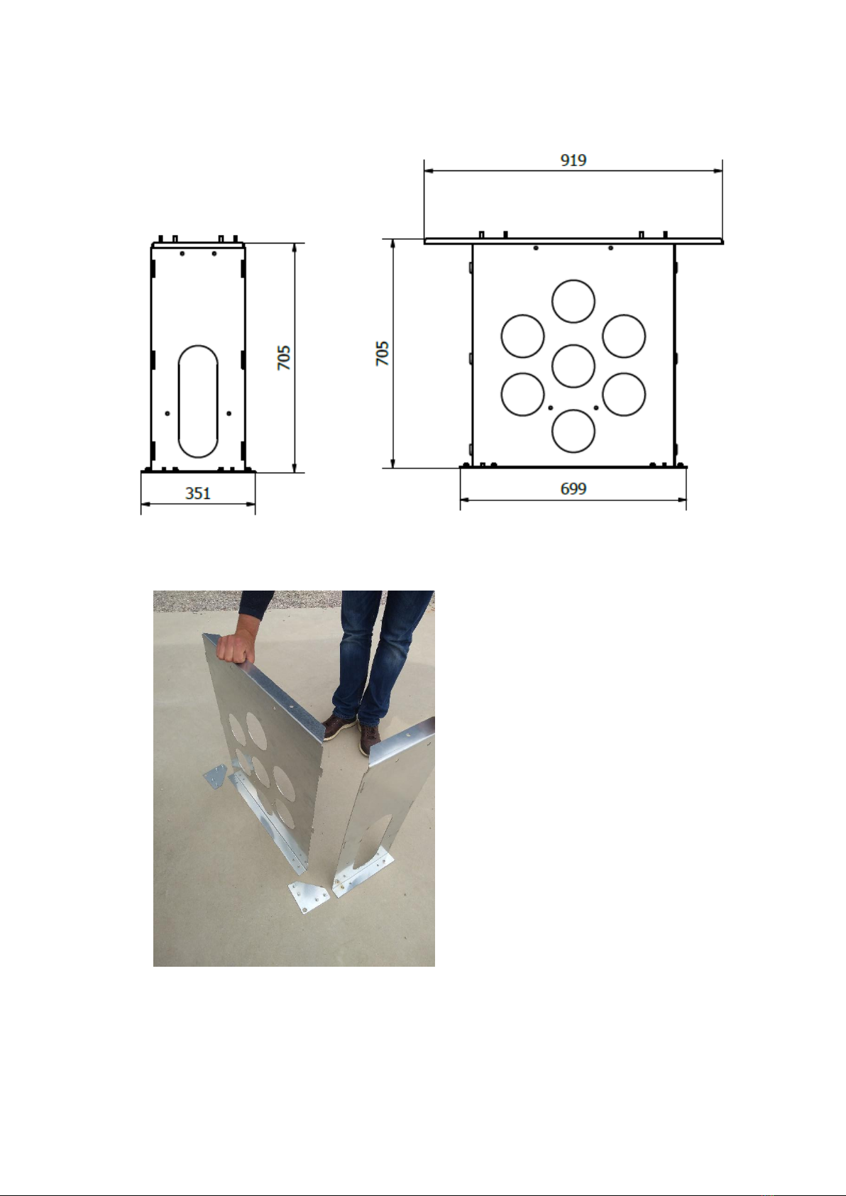
The dimensions of the assembled anchor are as followed.
Follow these instructions to assemble the different parts:
•Take one side panel, one front panel and two mounting corners.
•Join the front and side panel using the grooves and place the joined panels over a mounting
corner.

Smappee EV Base Ultra –Installation manual –English
15
•Take the second side panel and place this in the same position as the other side panel. Use
the grooves to join the side panel to the front panel.

Smappee EV Base Ultra –Installation manual –English
16
•Take the last front panel and use the grooves to mount the panel to the two side panels.
•This makes sure the four panels are joined together. They still need to be secured using the
mounting corners. Carefully tilt the anchor to slide the mounting corners into position. The
mounting corners can be fixed by hand tightening the supplied nuts.
Do NOT torque the nuts yet. This is done during the last step of the assembly.

Smappee EV Base Ultra –Installation manual –English
17
•Place the cover plate on the anchor and secure with the supplied nuts using a socket
wrench.
•Finally, the nuts of the mounting corners can be tightened with a socket wrench.

Smappee EV Base Ultra –Installation manual –English
18
•The EV Base Ultra anchor is now ready to be mounted and to host the charging station.
Mount the EV Base Ultra anchor
A stable and level ground needs to be prepared in advance. We advise a levelled concrete
foundation at ground level minus the height of the anchor. It is also possible to have the foundation
a little lower. This allows the EV Base Ultra to be integrated in the surrounding soil.
The EV Base Ultra can be placed maximum 3 cm below the top of the surrounding soil for aesthetic
purposes. It cannot be placed lower as there will be risk of water ingress.
To correctly install the EV Base Ultra anchor:
a. Create a foundation made of a dry mixture of sand and cement. The minimum dimensions of
this foundation are 450mm by 750mm. This is a bit larger than the dimensions of the anchor,
to make sure a stable foundation is created.
b. Reinforce the corners of the foundation using a concrete block.

Smappee EV Base Ultra –Installation manual –English
19
c. Make sure the concrete blocks are level in both directions. If not, adjust until level.
d. Place the EV Base Ultra anchor on the concrete blocks. If needed, the position of the anchor
is fixed by pushing a hub through the holes in the corner.
e. Route all necessary cables through the anchor. This includes power supply, ground and
ethernet cables.
f. Fill the anchor with concrete until half of the anchor is filled with concrete. It is normal that
some excess concrete pours out of the holes. Use this excess to further fix the anchor to the
foundation.
g. Wait for the concrete to cure before going to the next steps.
The EV Base Ultra anchor is now secured in place and ready for the EV Base Ultra to be mounted.
Place the EV Base Ultra on the anchor
a. While the EV Base Ultra is in the carboard box, first remove the backplate of the EV Base
Ultra. The back plate is the one without the Smappee avatar. This removes some weight
from the charger and provides extra grip.
Remove the backplate of the EV Base Ultra by unscrewing the 12 screws (using a 5 mm hex
screwdriver) and put it in a safe location where it cannot be scratched or damaged
otherwise; for instance in the packaging of the EV Base Ultra.

Smappee EV Base Ultra –Installation manual –English
20
b. Put the EV Base Ultra in an upright position. By tilting the EV Base Ultra back and forwards,
the cardboard is removed underneath the charging unit.
c. Remove the front plate of the EV Base Ultra by unscrewing the upper 4 screws (using a 5 mm
hex screwdriver). After unscrewing the 4 screws, the front plate can be removed by lifting
and moving it forward. Put it at a safe location where it cannot be scratched or damaged
otherwise; for instance in the packaging of the EV Base Ultra.
Other manuals for EV Base Ultra
1
Table of contents
Other Smappee Automobile Accessories manuals

Smappee
Smappee EV Base User manual

Smappee
Smappee EV Base Ultra User manual

Smappee
Smappee EV One Home User manual

Smappee
Smappee Infinity User manual

Smappee
Smappee EV Base User manual

Smappee
Smappee EV Base User manual

Smappee
Smappee EV One Home User manual

Smappee
Smappee EV One Home User manual

Smappee
Smappee EVB-2332-B-E User manual
Popular Automobile Accessories manuals by other brands


Tessera4x4
Tessera4x4 SOT-ROLL Series installation manual

ICI
ICI Alumilite Steps 840121412920 Direction for Installation and Use

BPW
BPW AirSave Operating and installation instructions

Menabo
Menabo HIMALAYA installation instructions

Brodit
Brodit 804741 ProClip installation instructions

Q'STRAINT
Q'STRAINT QUANTUM Use & care manual