Knauer WellChrom K-2600 User manual

●Wissenschaftliche Gerätebau Dr. Ing. Herbert Knauer GmbH ●Hegauer Weg 38 ●D-14163 Berlin DEUTSCHLAND
●Telefon: +49-(0)30 80 97 27-0 ●Fax: +49-(0)30 801 50 10 ●Email: [email protected] ●www.knauer.net
User Manual / Handbuch
Fast scanning
Spectro-Photometer K-2600
Schnell scannendes
Spektralphotometer K-2600
V7016, 09/2002

CONTENTS
Using this Manual...................................................................................... 5
Conventions in this manual ................................................................. 5
SOP´s in this manual...........................................................................5
General Description .................................................................................. 6
Basic Concepts of the K–2600 UV detector............................................. 7
Optical Path of the K–2600 UV detector............................................. 7
Preparing the K–2600 UV detector for Operation ..................................... 7
Unpacking ............................................................................................ 7
Power Supply, ON/OFF, Self Tests .................................................... 7
Installation of the Flow Cell.................................................................. 8
Front Panel Controls ................................................................................. 8
Front View of the K–2600 UV detector ............................................... 8
Function of Foil Keys ...........................................................................9
Arrow Keys ..................................................................................... 9
Numeric Keys ................................................................................. 9
AUTOZERO.................................................................................... 9
SCAN .............................................................................................. 9
Rear Panel View of the K–2600 UV detector ..................................... 9
Operating the Photometer ......................................................................10
Display and Menu Structure .............................................................. 10
Main Menu .........................................................................................10
Appearance of Cursor and Data Input .............................................. 10
The SETUP Menu ........................................................................11
Das GLP Menu.............................................................................14
Das LINK Menu ............................................................................ 14
The VIEW Menu ........................................................................... 15
Direct Control of the K–2600 UV detector ........................................15
Selecting wavelength(s) ....................................................................16
Programming the K–2600 UV detector.............................................17
Creating Programs .......................................................................17
Program Execution.......................................................................19
Creating Program Links ...............................................................20
Programming a link ...................................................................... 20
Running program links .................................................................21
Deleting Programs and Program Links ....................................... 21
Wake Up-Program........................................................................21
Using the Wake Up program ....................................................... 22
Scanning UV-Spectra ........................................................................ 22
The Scan Menu ............................................................................ 22
Scan Autozero ..............................................................................23
Performing wavelength scans...................................................... 23
Output of Scan Data.....................................................................23
Connecting other Instruments to the K–2600 UV detector....................24
Using the Event and Remote Sockets .............................................. 24
Assembling Plug Strips......................................................................24
Event Socket ................................................................................24
Remote Socket.............................................................................25

3
RS 232 Serial Interfaces .............................................................. 25
The KNAUER Net ........................................................................ 26
List of display messages.........................................................................26
Software Control of the K–2600 UV detector......................................... 26
Preparing for Software Control.......................................................... 27
Installing the KNAUER Net .......................................................... 27
Configuring the KNAUER Net...................................................... 27
Simple Maintenance ............................................................................... 28
Control of the lamp´s functionality..................................................... 28
Changing the lamp ............................................................................ 28
Cleaning the flow cell......................................................................... 28
Analytical flow cells ...................................................................... 29
Preparative flow cells ................................................................... 29
Adjusting the path length of the preparative flow cells ..................... 30
Flow cells with fiber optical connectors............................................. 30
Spare parts and accessories .................................................................. 31
Standard delivery............................................................................... 31
Spare Parts ........................................................................................ 31
Available Flow cells for your K–2600 UV detector ........................... 32
Analytical Cells ............................................................................. 32
Preparative Cells .......................................................................... 32
U-Z ViewMikro-Durchflusszellen / CE Zellen .......................... 32
Spare parts for flow cells ................................................................... 32
Analytical Cells ............................................................................. 32
Preparative Cells .......................................................................... 32
Technical Data ........................................................................................ 33
Declaration of conformity ........................................................................ 34
Guarantee statement .............................................................................. 35
INHALT
Hinweise zum Gebrauch des Handbuchs............................................. 37
Konventionen in diesem Handbuch .................................................. 37
SOP´s in diesem Handbuch.............................................................. 37
Allgemeine Beschreibung....................................................................... 38
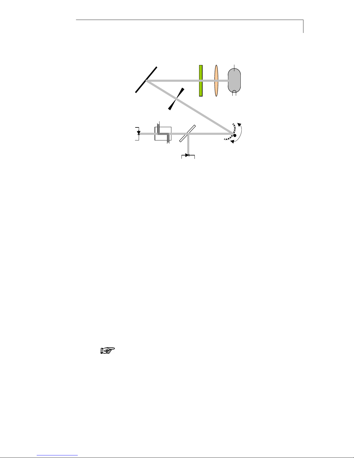
Prinzipbeschreibung des K-2600 UV-Detektors .................................... 39
Optischer Weg im K-2600 UV-Detektor............................................ 39
Inbetriebnahme des K-2600 UV Detektors ............................................ 39
Auspacken ......................................................................................... 39
Stromversorgung, Ein/Aus, Autotest................................................. 39
Installation der Messzelle .................................................................. 40
Steuerelemente....................................................................................... 41
Frontansicht des K-2600 UV Detektors ............................................ 41
Funktion der Folientastatur................................................................ 41
Pfeiltasten ..................................................................................... 41
Nummerische Tasten................................................................... 41
AUTOZERO ................................................................................. 41
SCAN............................................................................................ 41
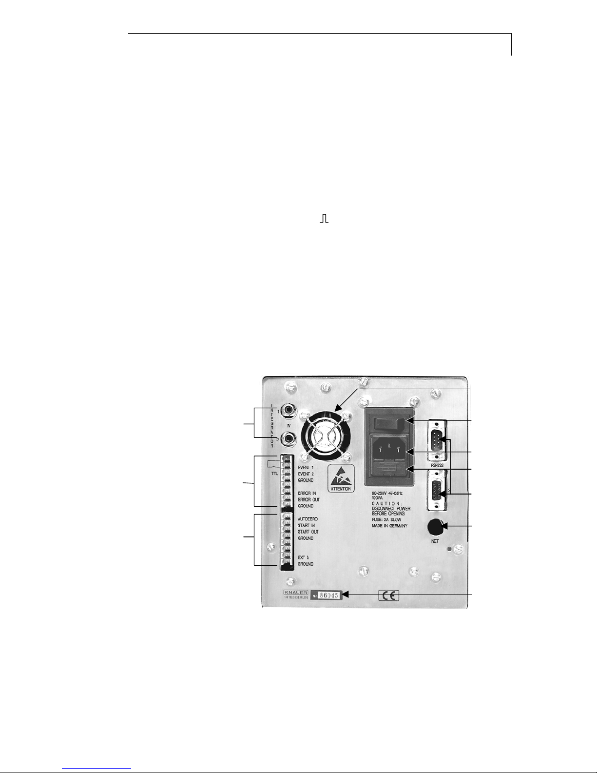
Rückansicht des Photometers .......................................................... 42
Betrieb des Photometers ........................................................................ 42
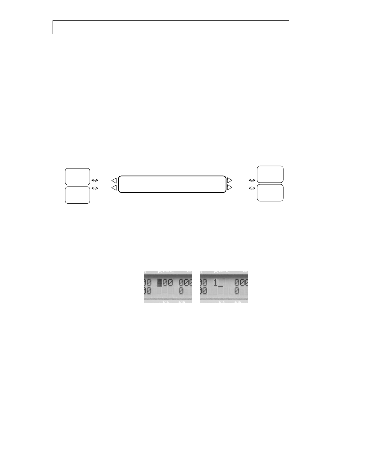
Display und Menüstruktur.................................................................. 42
Hauptmenü / Arbeitsbildschirm ......................................................... 43
Cursorerscheinung und Dateneingabe............................................. 43
Das SETUP Menü........................................................................ 43
Das GLP Menü............................................................................. 47

4
Das LINK Menü ............................................................................ 47
Das VIEW Menü...........................................................................48
Direkte Steuerung des K-2600 UV Detektors...................................48
Wellenlängenauswahl........................................................................ 49
Programmierung des K-2600 UV Detektors.....................................50
Erstellung von Programmen ........................................................50
Programmausführung ..................................................................52
Erstellung von Programmverknüpfungen....................................53
Programmierung von Verknüpfungen .........................................54
Ablauf von Programmverknüpfungen.......................................... 54
Löschen von Programmen und Programmverknüpfungen.........54
Wake Up Programm.....................................................................55
Nutzung des Wake Up Programms.............................................55
Scannen von UV-Spektren................................................................ 55
Das Scan Menü............................................................................ 55
Autozero Scan.............................................................................. 56
Durchführung von Wellenlängen Scans ...................................... 56
Ausgabe der Scandaten ..............................................................56
Verbindung anderer Geräte mit dem K-2600 UV Detektor ...................57
Verwendung der Event- und Fernsteuerungsleiste..........................57
Montage der Anschlussstecker......................................................... 57
Event Anschluss...........................................................................57
Fernsteuerungsanschluss............................................................58
RS 232 Serielle Schnittstelle........................................................ 58
Das KNAUER Netz ......................................................................58
Liste der Displaymeldungen ...................................................................59
Softwaresteuerung des K-2600 UV Detektors....................................... 59
Vorbereitung für die Software Steuerung .........................................60
Installierung des KNAUER Netzes ..............................................60
Konfigurieren des KNAUER Netzes ............................................ 60
Einfache Wartung.................................................................................... 61
Kontrolle der Lampenfunktion ........................................................... 61
Lampenwechsel.................................................................................61
Messzellenreinigung.......................................................................... 62
Analytische Messzellen................................................................ 62
Präparative Messzellen................................................................ 62
Festlegung der Länge präparativer Messzellen ...............................63
Messzellen mit Lichtleiteranschluss..................................................64
Ersatzteile und Zubehör..........................................................................64
Standardauslieferung ........................................................................64
Ersatzteile .......................................................................................... 64
Verfügbare Messzellen für den K-2600 UV Detektor ....................... 65
Analytische Durchflusszellen .......................................................65
Präparative Durchflusszellen .......................................................65
U-Z ViewMikro-Durchflusszellen / CE Zellen .......................... 65
Messzellenersatzteile für................................................................... 65
Analytische Messzellen................................................................ 65
Präparative Messzellen................................................................ 65
Technische Daten ...................................................................................66
Konformitätserklärung............................................................................. 67
Garantiebedingungen .............................................................................68

Using this Manual 5
Using this Manual
This manual refers to the WellChrom K–2600 UV-Detector Firmware
Revision 1.06 or higher. It is valid for any combination with analytical
flow cells order number A 4061, A 4042, A 4045, preparative flow cells
order number A 4066, A 4067, A 4068, A 4069, A4095 and all
U-Z View™ micro flow cells in standard and fiber optic version.
Conventions in this manual
Special Warnings are indicated by the marginal warning sign and
printed in bold letters.
The marginal lamp symbol indicates helpful advice’s.
Important Hints are marked by the marginal hand symbol.
Arrows in an outlined form like this example used in block diagrams,
indicate an automatic program run and change to the next line without
the necessity of manual interventions.
Arrows like this, used in block diagrams, indicate that the user is
asked to press the corresponding arrow keys
⊲∆∇⊳The triangles symbolize the use of corresponding arrow keys.
SOP´s in this manual
The Standard Operating Procedures (SOP) provided with this manual
offer a convenient way of structuring complex tasks in the operation of
your WellChrom K-2600 UV detector. They include step-by-step
instructions leading the user through all routine tasks during operation.
They can be used for documentation purposes and be copied, applied
signed, and filed in order to document the performance of the
instrument.
Please operate the instrument and all accessories according to
instructions and SOP´s in this manual. This ensures proper
results and longevity of your equipment.
SOP´s in diesem Handbuch
SOP 1 Installation of the Flow Cell..................................................8
SOP 2 Time Programming of Absorption Wavelength.................17
SOP 3 Programming events for control of a fraction collector .....18
SOP 4 Assembling Plug Strips......................................................24
SOP 5 Changing the lamp.............................................................28
SOP 6 Cleaning an analytical flow cell .........................................29
SOP 7 Cleaning a preparative flow cell ........................................29
SOP 8 Changing the path length ..................................................30

6 General Description
General Description
The WellChrom K–2600 UV detector is a new, programmable and fast
scanning detector. It is capable of measuring up to four wavelengths
simultaneously. In stand alone mode two wavelengths can be used
simultaneously and four spectra can be stored in the detector. The scan
function provides you with spectral information of your substances over
the whole wavelength range without stopping the eluent flow of your
HPLC system.
Up to 20 time programs with 99 program lines can be stored and are
permanent available, up to nine links between programs can be
defined. The instrument is ideally suited for use as a stand alone
instrument as well as for use in a complete system under control of the
KNAUER HPLC software EuroChrom for Windows.
Wavelengths between 190 and 740 nm are selected using a moveable
grating monochromator with an accuracy of ± 1 nm in 1 nm steps. The
bandwidth is 8 nm or better. Additionally, a cut-off filter can be activated.
This filter suppresses secondary grating orders when measuring with a
deuterium lamp at wavelengths > 380 nm and thus ensures the
selectivity of the measurement. A halogen lamp for the visible
wavelength range can easily be installed by the user.
Data acquisition and control of the K–2600 UV detector are performed
digitally and such allow trouble free operation of the instrument. Two
adjustable analog outputs and the option for external analog control are
also available. Additional features offered by the K–2600 UV detector
are the control of other instruments via event outputs, the control of a
fraction collector by time window and/or level sensing and the possibility
to give out ratio plots, e.g. for peak purity control, via the analog
outputs.
An integrated self-test and self-calibration performed after switching on
ensures reliable and reproducible operation. The highly sensitive
detector features a extremely low noise level (≤1 x 10⁻⁵ AU) and
baseline drift (≤10 x 10–5 AU/h). The autozero function is available
across the entire measuring range. The K–2600 UV detector satisfies
all GLP requirements of a regulated laboratory.
A rich palette of flow cells available for the KNAUER photometers,
ranging from cells for Nano-HPLC with flow rates < 10 0 nl/min to
preparative cells for up to 10 l/min, make the photometer K–2600 highly
flexible in the full range of LC applications.
Moreover, a version of the K–2600 UV detector equipped with fiber
optical connectors of the cell is available. This enables the spatial
separation of detector and flow cell and thus the use of these
instruments in hazardous locations.

Basic Concepts of the K–2600 UV detector 7
Basic Concepts of the K–2600 UV detector
Optical Path of the K–2600 UV detector
4321
5
10
98 7 6
Fig. 1 Optical path of the K–2600 UV detector
The light emitted from the lamp [1] is bundled and guided to a grating
monochromator [5] for defining the desired wavelengths. After passing
a filter [7] (optional) the beam is splitted by a semi transparent mirror [8].
One beam gives a reference signal [11], the other beam is guided
through the cell [9] where optical absorption is measured [10]. The
difference or the ratio of the two signals can be calculated.
Preparing the K–2600 UV detector for Operation
Unpacking
After unpacking, please check the device and accessories thoroughly
for any damage that may have occurred during transport. If necessary,
put forward any claim for damages to the carrier.
Use list “Standard delivery” on page 31 and check that the K–2600 UV
detector delivery is complete. Please contact our service department if
you miss something or if you need support. Please fill out the guarantee
registration card and return it to us immediately.
Power Supply, ON/OFF, Self Tests
The K–2600 UV detector is equipped with an universal power supply
which operates in the range from 90 to 260 Volts AC. A manual setting
of the supply voltage is therefore not required.
Make sure that mains power supply is properly grounded and a
correct three-pronged power cable is used.
Connect the power cable to the device and the socket, and then switch
the device on with the ON/OFF key, see [5.2] and [5.3] in Fig. 3 on page
8.
After switching on, the display, see 1 in Fig. 2 on page 8, is indicating
some information, such as HPLC SPECTRAL PHOTOMETER, and the
VERSION of the internal Software, e.g. 1.07.
The power-on selftest performed includes a check of the electronic
function, wavelength calibration, see „AUTO CALIBRATION“ on page
1. Lamp
(deuterium or halogen)
2. Lens system
(quarz optics)
3. Cut-off filter
4. Concave mirror
5. Slit
6. Moveable grating
monochromator
7. Half transparente mirror
8. Flow cell
9. Photo diode
10.Reference photo diode

8 Front Panel Controls
11 and an autozero. Successful completion of selftest is indicated by
systemtest ok.
Then the lamp of the device is heated up until the final, constant
working temperature has been reached. During heating up the display
shows hea in the lower left position. The starting routine is completed
by an automatic calibrating procedure, and when indicating on the
device is ready for operation.
Installation of the Flow Cell
The K–2600 UV detector comes factory configured without flow cell.
Before operating the photometer, you need to install a appropriate flow
cell from the palette of flow cells available from KNAUER.
SOP 1 Installation of the Flow Cell
This instruction refers to the K–2600 UV detector without fiber optical
connectors. Refer to Fig. 2 „Front panel of the K–2600 UV detector“ on
page 8.
1. Loosen the two „Knurled cell screws“ [3] with the fingers and
remove them.
2. Pull out the „Flow cell housing“ [4].
3. Take the cell or dummy cell with two fingers and remove it
upward.
4. Insert the new „Flow cell“ [7] and make sure that the engraved
specifications point towards the user (…can be read), and the
fixing hole on the back side of the cell meets the corresponding
metal pin of the photometer‘s housing.
5. Now push the complete system towards the housing, insert the
two screws and thighten them manually.
Front Panel Controls
Front View of the K–2600 UV detector
1. Display information
2. Foil key area
3. Knurled cell screws
4. Flow cell housing
5. Flow cell cradle
6. Outlet
7. Flow cell
8. Path length of cell
9. Inlet
1
2
3
4
5
9876
10
Fig. 2 Front panel view of the K–2600 UV detector

Front Panel Controls 9
Function of Foil Keys
See „Foil key area“ [2] in Fig. 2 „Front panel of the K–2600 UV
detector“.
Arrow Keys
The yellow, arrow-shaped keys can be used for moving and positioning
the cursor in the display and for confirming an entered value.
Numeric Keys
All ten numeric keys 1 to 0 enable entering of numeric values at the
position of the cursor.
In certain menues, the keys 0, 1 and 2 are used to RUN (1) or to HOLD
(0) a defined program, or to insert event programmings, e.g. 2 to
program the event pulse .
AUTOZERO
When pressed shortly, this performs an auto-zero over the whole
wavelength range. Pressing longer than two seconds starts a scan
autozero.
SCAN
The yellow colored SCAN key switches to the SCAN menu. After
switching to this menu, pressing the SCAN button again triggers a scan
over the chosen wavelength range.
Rear Panel View of the K–2600 UV detector
5.6
5.3
5.2
5.1
5.4
5.5
5.7
5.10
5.9
5.8
Fig. 3 Rear panel view of the K–2600 UV detector
5.1 Fuse compartment 5.6 Fan
5.2 Power connector 5.7 Serial number
5.3 ON/OFF switch 5.8 Terminal strip
Remote connectors
5.4 RS-232 interfaces 5.9 Terminal strip
Event connections
5.5 Socket for Ethernet-
connection
5.10 Analog outputs
(to recorder or integrator)

10 Operating the Photometer
Operating the Photometer
Display and Menu Structure
After switching on the instrument, see chapter „Power Supply, ON/OFF,
Self Tests“ on page 7, the device is ready for operation, showing on the
display the main menu or operation screen. The center part of Fig. 4
shows an example of the main menu.
Using one of the arrow keys of the foil keypad, the blinking cursor can
be moved to all positions of the menu. If the cursor has reached an
exterior position in the menu, e.g. ON in the lower left corner of the main
menu, one more pressing of ⊳for at least 2 seconds will indicate the
VIEW MENU on the display.
Main Menu
Load Edit Prog Events: 2 Signal 1 Signal 2
Prog Clear 0 off 0 on 1 [au] [au]
01 -- 00 .0000 -.0001
ON 000.0 190 740
Hold 0 Time λ1 λ2
Run 1 [min] [nm] [nm]
LINK
Menu
V
IE
W
Menu
Link
Vie
w
SETUP
Menu
GLP
Menu
Setup
GLP
Fig. 4 Overview menu structure
Some menus consist of several pages, indicated by a rhombus ♦in the
lower left corner of the display. If you place the cursor on this rhombus,
all menu pages can be accessed by pressing ∆or ∇.
Appearance of Cursor and Data Input
Fig. 5 Blinking cursor Cursor waiting for data input
The blinking cursor can be moved to any desired position, see Fig. 5
(left).
Once the position for data input has been reached, simply press the first
numeric key to start data input. Now the cursor changes to underline
character beside the first input, as you can see Fig. 5 (right). Enter next
digit and proceed until numeric input is complete. Confirme and leave
this position by pressing any arrow key.
Data input mode is disabeled automatically, if a time limit of 60 seconds
without pressing any key is reached.

Operating the Photometer 11
The SETUP Menu
In the SETUP menu parameters for the operation of the K–2600 UV
detector can be adjusted. These parameters comprise values for
operation of the instrument.
DATE: 11.11.99 dd.mm.y
y
TIME: 08.31.10 hh.mm.ss
TIME CONSTANT: 1s
AUTO CALIBRATION
LAMP: Deuterium ON
no:001 00457.1
SIGNAL sig:0.1485
absorbtion ref:0.0725
SCAN OUT:
Speed:5 steps/s
A
NALOG OUT FULL SCALE:
1 au -> 1V
A
NALOG OUT OFFSETS:
+000.00mV +000.00mV
FRACTION: dela
y
000.0s
-- level: 0.0000 au
CONTROL: KNAUER NET
Baud rate 9600
ANALOG IN:
Set Zero actual_ :000
Main Menu Setup
GLP
Fig. 6 Block diagramm overview SETUP menu
TIME CONSTANT
You can select smoothing the signal with a time filter. The value can be
chosen between 0,1; 0,2; 0,5; 1; 2; 5 and 10 seconds. The bigger the
value for the time constant, the more the signal is smoothened. For
most analytical purposes, a time constant of 1s is best suited.
AUTO CALIBRATION
(Second line in the window TIME CONSTANT):
Moving to this field and pressing or starts the procedure for the
calibration of the wavelength scale. It searches automatically for
reference points within the spectra of the lamp for reliability and
reproducibility of the wavelength. The points used for calibration are the
zero order reflection of the grating (000 nm) and the Hαspectral line of
Deuterium (656 nm). Auto calibration is performed automatically on
power on.
LAMP
You can specify the lamp type (Deuterium/Halogen). Changing the
lamp type resets the lamps working time after a control question, the
lamp number is incremented. The number of the lamp cannot be edited.
In the field with working time of the actual lamp you can reset this GLP
value after a control question. The lamp number is then incremented.
This function should be used only when replacing a deuterium lamp.
The ON/OFF field enables you to switch off the lamp without switching
off the instrument.

12 Operating the Photometer
Load Edit Prog Events: 2 Signal 1 Signal 2
Prog Clear 0 off 0 on 1 [au] [au]
LAMP: Deuterium ON
no:001 00028.5
Hold 0 Time λ1 λ2
Run 1 [min] [nm] [nm]
Link
V
ie
w
Setup
GLP
Fig. 7 Menu for lamp specifications
Signal
You can select the signal source used for all data outputs. This includes
display on the operation screen as well as analog and digital data
outputs. You can select the options absorption, signal and reference
channel. The values sig and ref give the measured light intensity on the
signal and the reference channel respectively. The sig and ref values
range between 0 and 1, their absolute values are dependent on the
wavelength, the solvent, the flow cell used and the age of the lamp.
SCAN OUT
You can select the output speed of scan data via integrator output.
Available values are 1, 2, 5, 10, 20 and 50 steps per second.
ANALOG OUT FULL SCALE
You can scale the two integrator outputs according to your needs.
Load Edit Prog Events: 2 Signal 1 Signal 2
Prog Clear 0 off 0 on 1 [au] [au]
ANALOG OUT FULL SCALE:
0.001 au -> 1V
Hold 0 Time λ1 λ2
Run 1 [min] [nm] [nm]
Link
View
Setup
GLP
Fig. 8 Menu for scaling the analog outputs
In the first field you can choose the signal range covered by the output
signal. Values that can be chosen by arrow keys from 10-4 to 10 AU in
16 steps. In the right hand field you can choose the maximum output
voltage from 0.1, 1 and 10 V.
ANALOG OUT OFFSETS
You can set an offset to the two integrator outputs. The output voltage
of the outputs is set to zero during the self test of the instrument. In this
window, you can set a numerical value for an offset in mV units that will
be added to the corresponding signals on the analog outputs. This
function can be useful when using a chart recorder to separate the
charts for the two channels.
ANALOG IN
You can calibrate the analog input for external wavelength control.
Activating Set-Zero by pressing ∆or ∇on this field defines the actual
input voltage as zero, wavelength 000 nm. Then a signal is applied, e.g.
5V. The actual „λ“ field shows the interpreted wavelength, that should

Operating the Photometer 13
be 500 nm with the preset conditions of 100 nm=1 V. This wavelength
value can then be modified with the arrow keys ∆or ∇, which creates a
second calibration point.
CONTROL
The instrument can be set to different external control modes. You can
choose between KNAUER-NET, where the baud rate is currently
limited to 9600, RS-232, RS-485 and ANALOG. When choosing the
ANALOG option, only one wavelength can be used and controlled by
the analog input voltage. The operation screen is modified
correspondingly. The options RS-232 and RS-485 enable the use of a
RS-232 or a RS-485 protocol for controlling the instrument with a
terminal program.
The option KNAUER-NET is used when operating the K–2600 UV
detector as a stand alone instrument or for combinations with other
KNAUER instruments, e.g. for external control with the EuroChrom
software (see chapter „Software Control of the K–2600 UV detector“ on
page 26.
DATE/TIME
Allows setting system date and time.
FRACTION
This window provides you with the possibility to control a fraction
collector by using the event outputs of the K–2600 UV detector.
Additionally, signal levels to be exceeded for fraction collection and a
delay time respecting the dead volume of the capillaries between
detector and collector can be set.
Load Edit Prog Events: 2 Signal 1 Signal 2
Prog Clear 0 off 0 on 1 [au] [au]
FRACTION: delay: 090.0 s
level: 0.3205 au
Hold 0 Time λ1 λ2
Run 1 [min] [nm] [nm]
Link
Vie
w
Setup
GLP
Fig. 9 Menu for setting up the fraction collector control
Enter a delay time in seconds in the first line. Set the events for control
of the in the second line, the event that controls the fraction collector
can be chosen. Possible values are E1 or E2.
E1 activates a relay output, E2 a TTL output. The corresponding
connector on the rear side of the instrument can be connected to the
fraction collector.
In the field level you can set a minimum signal level that must be
exceeded before fraction collection starts. Both functions, level and
event, are evaluated in a logical and functions. This means, that the E1
output is activated when the level is exceeded during activation in the
time table of a method. In case of missing time programs the
appropriate event has to be set to „1” in the operation screen. If fraction
collection is controlled by the signal level only, the event output
becomes active every time the signal exceeds the preset signal level.

14 Operating the Photometer
Das GLP Menu
The GLP report reports the operating statistics of the photometer.
GLP: Lamp no:0001
0457.3 h starts:0061
GLP: Total working time
(lamp) 00457.3 h
GLP: Total working time
(motor) 00693.2 h
GLP: Last error codes
GLP: Installation date
15.06.97
GLP: Last service
15.06.98
Setup
GLP
Main Menu
Fig. 10 Block diagram GLP menu
Das LINK Menu
The link menu is used when running links, i.e. the pre-defined run of
program combinations. In this menu the momentary status of the
program links can be monitored.
no LINK running
Link
Vi e
w
Main Menu
LINKS: P:program
(21..29) R:repeat
with LINK running
Link
Vi e
w
Main Menu
L1: -- No01 P01 R-05
RUN No02 P13 R10 ↓
L1: -- No02 P13 R-09
↑
RUN No03 P01 R10 ↓
L1: -- No03 P01 R-02
↑
RUN
Fig. 11 Block diagram LINK menu

Operating the Photometer 15
In the first line of the menu the momentary status can be observed, the
number of runs R-xx to be performed counts downwards. In the second
line the next step of the link to be executed is shown. Arrows at the right
side of the display indicate, that more program lines above and below,
respectively, do exist.
For more information on links, see chapter “Creating Program Links” on
page 20.
The VIEW Menu
The View menu gives an overview of existing programs and program
links. See Fig. 12 for an example where programs 01, 02, 03, 04 and 11
and link 21 have been defined and do exist.
Programs: 01 02 03 04 __
(01..10) __ __ __ __ __
Programs: 11 __ __ __ __
(11..20) __ __ __ __ __
Links: 21 __ __ __ __
(21..29) __ __ __ __ __
Link
Vi e
w
Main Menu
Fig. 12 Block diagram VIEW menu
Direct Control of the K–2600 UV detector
Direct Control of the K–2600 UV detector is performed via operation
screen. Many functions like choice of wavelength(s) except scanning,
can be controlled from the operation screen.
Programs can be used for determining and changing wavelengths or
setting signal events during runs. The K–2600 UV detector features
storage and selection between up to twenty different programs with a
maximum number of 100 program lines for each program. You can
store nine different links for calling programs within programs.
The most powerful feature of the K–2600 UV detector is its ability to
scan UV-spectra with a speed of approx. 100 nm/s on flow. Scans are
handled in the SCAN menu, which is accessed simply by pressing the
SCAN button.
After power on, the instrument starts automatically with the last used
program. In case no programs had been loaded, the standard program
is defined to be No. 01, as shown in Fig. 13.
Load Edit Prog Events: 2 Signal 1 Signal 2
Prog Clear 0 off 0 on 1 [au] [au]
01 -- 00 -.2030 .0109
ON 000.0 +381 +400
Hold 0 Time λ1 λ2
Run 1 [min] [nm] [nm]
Link
Vie
w
Setup
GLP
Fig. 13 Standard display with cut-off filter activated

16 Operating the Photometer
Selecting wavelength(s)
Position the cursor on one of the two wavelength fields and select the
wavelength by entering the desired values with the numeric keys. If you
want to use one single wavelength, enter a Zero in the unused fields.
Entering zero deactivates the respective wavelength. If you use both
wavelengths, the polychromator moves between the positions
corresponding to the selected wavelengths. This movement is
performed with a frequency of 10 Hz that cannot be changed and. You
can hear the motor of the polychromator as a high frequency tone.
A cut-off filter for suppressing secondary grating orders is activated
automatically if one or both wavelength(s) exceed 381 nm and a
deuterium lamp is installed. The use of the filter is displayed by a
superscripted +, as shown in Fig. 13.
Output options: The Output of absorption signals can be configured.
Move the cursor to the signal fields. Choose between different options
by pressing any numeric key. Options are:
−Signal inversion indicated by a little superimposed minus sign.
Two different ratio plots are available:
−Wavelength (1) divided through wavelength (2) and
−vice versa.
Ratio plots are indicated by symbol 1/2 and respectively 2/1 at the
decimal point of the absorption value Fig. 14.
Fig. 14 Inversion of the signal and ratio plots: Set indicated output
options
Ratio plots contain information on peak purity. It is calculated by dividing
the intensity values at two different wavelengths. It is possible to
measure the absorption at one wavelength and to monitor
simultaneously the ratio of absorption between this wavelength and
another one. Ratio plots can be accessed at either analog out
connector or via digital data acquisition.
The scaling of the analog outputs can be adjusted to different values of
Absorption Units or to different voltage values. For detailes see section
„ANALOG OUT FULL SCALE:“ on page 12 in section „The SETUP
Menu“.
EVENTS — The EVENT outputs on the rear side of the instrument
provide time programmed signals to other instruments. All features,
together with that of the remote control socket, is described in chapter
„Connecting other Instruments to the K–2600 UV detector“ on page 24.
When working without a time program, using events enables fraction
collection, as described in section "FRACTION" on page 13 in chapter
„The SETUP Menu“.

Operating the Photometer 17
Programming the K–2600 UV detector
Creating Programs
Time displays are given in minutes with decimal calculation of
seconds, i. e. 0.3 min = 18 s. Time resolution during input is 1/10
min, during program runs 1/100 min. All programs are saved
permanently.
Wavelengths and events can be changed as a function of time. Setup
parameters such as scaling of the analog outputs cannot be time
programed. All options for analog outputs like ratio plots can be defined
for entire programs and will be used when loading this program.
The K–2600 UV detector can store up to twenty programs. By moving
the cursor to the VIEW menu, you can check the availability and
allocation of program numbers.
Use the EDIT mode for modifying or creating programs. Move the
cursor to the „Edit Prog” field and enter the desired program number
with numeric keys. Any numeric values can be overwritten. Pressing
any arrow key confirms the actual value.
The first line of a program is the start time at 0 min. This time cannot be
changed. Message Start time is fixed appears on editing this line. The
maximum value for time is 999 min.
To edit a new time line, move the cursor to the time field and press ∇. If
this line is empty, in the time field will be displayed ***.*
Load Edit Prog Events: 2 Signal 1 Signal 2
Prog Clear 0 off 0 on 1 [au] [au]
01 03 -- .--- .---
ON ***.* --- ---
Hold 0 Time λ1 λ2
Run 1 [min] [nm] [nm]
Link
View
Setup
GLP
Fig. 15 Empty line in program no. 3
You can delete a program line if you enter 0 in the field time and press
any arrow key. The message Delete this line? Confirm by cursor will
be displayed. You can confirm deletion if you press any arrow key. If
you presse a numeric key, or wait for 60 seconds, deletion will be
aborted.
Values 0, 1 and 2 can be used for programming of events, see chapter
„Connecting other Instruments to the K–2600 UV detector“ on page 24.
SOP 2 Time Programming of Absorption Wavelength
Use this instruction for programming the absorption wavelength as a
function of time.
1. Activate the operation screen, see Fig. 4 on page 10.
2. Move cursor to the field Edit Prog, press any numeric key to
generate a numeric labe for the new program. Press any arrow
key to confirm and enter edit mode for the new program.
3. The cursor is automatically moved to Time 000.0, which is the
fixed start time.

18 Operating the Photometer
4. Press ⊲to go to field λ1. Enter desired wavelength. Move cursor
to field λ2 and enter your second desired wavelength. The
display should resemble section B in Fig. 16 on page 19.
5. Press ∇to create an new program. The display should resemble
section C in Fig. 16 with the blinking cursor on the first asterisk.
6. Press 1 and 0 and then ⊲to define time step 10.0 min. Enter
field λ1 and put in 240 nm and complete entering by pressing ∇.
The value for λ2 (254 nm) is kept constant as long as no changes
are made.
7. Repeat the last two steps, define time step 20.0 min and enter
280 nm. The display should resemble section D in Fig. 16.
To run a program it must be loaded, see chapter „Program
Execution“ on page 19.
SOP 3 Programming events for control of a fraction collector
Use this instruction to control a fraction collector via the K–2600 UV
detectors EVENT socket using signal level and a defined time window.
1. Enter the SETUP menu and proceed to the window FRACTION,
see Fig. 9 on page 13.
2. Enter the desired value for the signal level, e.g. 0.32 AU, the
delay volume if needed, and select E1 for relay output.
3. Return to the operation screen
4. Move cursor to field Edit Prog, press any numeric key to generat
a identifyer for you new program. Press ∇to confirm and to enter
the edit mode for the new program.
5. At the time step 0 min the Events-field rests unchanged. At time
5 min program Events 1 0, see Fig. 17 on page 20 and prepare
deactivating of the event at 10 min by entering 0 0 again.
Event 1 (relay output) will be enabled from 5 to 10 minutes. Any peaks
within the time window exceeding the signal level (0.32 in this example)
defined in the SETUP menu leads to generation of a event at the signal
outputs.
Peaks exceeding the signal level between 0 and 5 minutes will not
produce an event signal.
The value for level chosen in the SETUP menu, will always apply
for all programs, it cannot be set individually for single programs.

Operating the Photometer 19
Load Edit Prog Events: 2 Signal 1 Signal 2
Prog Clear 0 off 0 on 1 [au] [au]
01 03 -- --- ---
ON ***.* --- ---
Hold 0 Time λ1 λ2
Run 1 [min] [nm] [nm]
Link
Vie
w
Setup
GLP
Load Edit Prog Events: 2 Signal 1 Signal 2
Prog Clear 0 off 0 on 1 [au] [au]
01 03 00 --- ---
ON 000.0 220 254
Hold 0 Time λ1 λ2
Run 1 [min] [nm] [nm]
Link
Vie
w
Setup
GLP
Load Edit Prog Events: 2 Signal 1 Signal 2
Prog Clear 0 off 0 on 1 [au] [au]
01 03 00 --- ---
ON 020.0 280 254
Hold 0 Time λ1 λ2
Run 1 [min] [nm] [nm]
Link
Vie
w
Setup
GLP
Load Edit Prog Events: 2 Signal 1 Signal 2
Prog Clear 0 off 0 on 1 [au] [au]
01 03 00 --- ---
ON 010.0 240 254
Hold 0 Time λ1 λ2
Run 1 [min] [nm] [nm]
Link
Vie
w
Setup
GLP
A
B
C
D
Fig. 16 Four steps for creating a program
Program Execution
Programs must be activated prior to execution. Enter the desired
program number in the field Load Prog and confirme by arrow key. The
instruments settings are adjusted to all presets of that program. An
autozero is performed automatically every time a new program is
loaded.
The time table of the program is started by moving the cursor to the ON
field in the lower left corner of the display. Pressing 1then starts the
program. The display switches to RUN, and the elapsed time is
displayed in the field Time. Program execution can be interrupted by
pressing 0. It is stopped with the actual values, indicated by a blinking
time line. The message HOLD is displayed.

20 Operating the Photometer
Load Edit Prog Events: 2 Signal 1 Signal 2
Prog Clear 0 off 0 on 1 [au] [au]
01 07 00 .--- .---
ON 000.0 254 280
Hold 0 Time λ1 λ2
Run 1 [min] [nm] [nm]
Link
Vie
w
Setup
GLP
Load Edit Prog Events: 2 Signal 1 Signal 2
Prog Clear 0 off 0 on 1 [au] [au]
01 07 10 .--- .---
ON 005.0 254 280
Hold 0 Time λ1 λ2
Run 1 [min] [nm] [nm]
Link
Vie
w
Setup
GLP
Load Edit Prog Events: 2 Signal 1 Signal 2
Prog Clear 0 off 0 on 1 [au] [au]
01 07 00 .--- .---
ON 010.0 254 280
Hold 0 Time λ1 λ2
Run 1 [min] [nm] [nm]
Link
Vie
w
Setup
GLP
A
B
C
Fig. 17 Programming steps for example program no. 7
Execution of the program can either be continued by pressing 1and
returning to RUN again or it can be stopped by pressing 0again. If you
stop program execution the instrument will return to the parameters of
the start time. These initial parameters are activated also after a
program run is finished.
A program can also be started via input START IN on the rear panel of
the instrument. In case a trigger signal is applied to this input, the
system switches into mode RUN.
Creating Program Links
Program links are cross references to existing programs, which can be
defined and edited similar to programs themselves. Links cannot
reference other links.
In the editing mode links are defined and loaded as the reserved
program numbers 21 to 29, where program 21= L1, 22 = L2 etc.
Links have line numbers from No. 01 up to No. 99, every line containing
one program, one number for repetitions and a wait-status
programmable. The K–2600 UV detector can store up to 9 different
links, but the maximum number of programs used in all links is limited to
100. Each program may appear in any frequency in any link.
Programming a link
Enter the number of the desired link in the field Edit Prog, for example
22 for link L2 and press any arrow key to confirm. Part A in Fig. 18 is
showing that step, the cursor blinking at No**. Now press any numeric
key to generate a new, continuously numbered line. In this case No01
will appear.
Then use ⊲to move the cursor to P-field and choose the desired
program number, e.g. 03. Press again ⊲to put in at the R-field the
number of runs to be performed with the selected program, e.g. 05.
Table of contents
Languages:
Other Knauer Measuring Instrument manuals