SMAR FI302 Manual

FI 302ME

web: www.smar.com
smar
Specifications and information are subject to change without notice.
For the latest updates, please visit the SMAR website above.
BRAZIL
Smar Equipamentos Ind. Ltda.
Rua Dr. Antonio Furlan Jr., 1028
Sertãozinho SP 14170-480
Tel.: +55 16 3946-3510
Fax: +55 16 3946-3554
CHINA
Smar China Corp.
3 Baishiqiao Road, Suite 30233
Beijing 100873, P.R.C.
Tel.: +86 10 6849-8643
Fax: +86-10-6894-0898
FRANCE
Smar France S. A. R. L.
42, rue du Pavé des Gardes
F-92370 Chaville
Tel.: +33 1 41 15-0220
Fax: +33 1 41 15-0219
e-mail: smar.am@wanadoo.fr
GERMANY
Smar GmbH
Rheingaustrasse 9
55545 Bad Kreuznach
Germany
Tel: + 49 671-794680
Fax: + 49 671-7946829
MEXICO
Smar México
Cerro de las Campanas #3 desp 119
Col. San Andrés Atenco
Tlalnepantla Edo. Del Méx - C.P. 54040
Tel.: +53 78 46 00 al 02
Fax: +53 78 46 03
SINGAPORE
SmarSingapore Pte. Ltd.
315 Outram Road
#06-07, Tan Boon Liat Building
Singapore 169074
Tel.: +65 6324-0182
Fax: +65 6324-0183
USA
Smar International Corporation
6001 Stonington Street, Suite 100
Houston, TX 77040
Tel.: +1 713 849-2021
Fax: +1 713 849-2022
e-mail: sales@smar.com
Smar Laboratories Corporation
6001 Stonington Street, Suite 100
Houston, TX 77040
Tel.: +1 713 849-2021
Fax: +1 713 849-2022
e-mail: sales@smar.com
Smar Research Corporation
4250 Veterans Memorial Hwy.
Suite 156
Holbrook , NY 11741
Tel: +1-631-737-3111
Fax: +1-631-737-3892
e-mail: sales@smarresearch.com

Introduction
III
Introduction
The FI302 is of the first generation of Fieldbus devices. It is a converter mainly intended for interface
of a Fieldbus system to control valve or other actuators. The FI302 produces a 4-20 mA output
proportional to input received over the Fieldbus network. The digital technology used in the FI302
enables an easy interface between the field and the control room and several interesting features
that reduce considerably the installation, operation and maintenance costs.
The FI302 is part of Smar's complete 302 line of Fieldbus devices.
Fieldbus is not only a replacement for 4-20 mA or intelligent / smart transmitter protocols, it contains
much more. Fieldbus is a complete system enabling distribution of the control function to equipment
in the field.
Some of the advantages of bi-directional digital communications are known from existing smart
transmitter protocols: Higher accuracy, multi-variable access, remote configuration and diagnostics,
and multi-dropping of several devices on a single pair of wires.
Those protocols were not intended to transfer control data, but maintenance information. Therefore
they were slow and not efficient enough to be used.
The main requirements for Fieldbus were to overcome these problems. Closed loop control with
performance like a 4-20 mA system requires higher speed. Since higher speed means higher power
consumption, this clashes with the need for intrinsic safety.
Therefore a moderately high communication speed was selected, and the system was designed to
have a minimum of communication overhead. Using scheduling the system controls variable
sampling, algorithm execution and communication so as to optimize the usage of the network, not
loosing time. Thus, high closed loop performance is achieved.
Using Fieldbus technology, with its capability to interconnect several devices, very large control
schemes can be constructed. In order too be user friendly the function block concept was introduced
(users of SMAR CD600 should be familiar with this, since it was implemented several years ago).
The user may now easily build and overview complex control strategies. Another advantage is
added flexibility; the control strategy may be edited without having to rewire or change any
hardware.
The FI302, like the rest of the 302 family, has several Function Blocks built in, like PID controller,
Input Selector and Splitter/Output Selector, eliminating the need for separate control device. This
feature reduces communication and by that less dead-time and tighter control, not to mention the
reduction in cost.
Other function blocks are also available. They allow flexibility in control strategy implementation.
The need for implementation of Fieldbus in small as well as large systems was considered when
developing the entire 302 line of Fieldbus devices. They have the common features of being able to
act as a master on the network and be configured locally using a magnetic tool, eliminating the need
for a configurator or console in many basic applications.
Get the best result of the FI302 by carefully reading these instructions.

FI302 - Operation and Maintenance Instruction Manual
IV
WARNING
This Manual is compatible with version 3.XX, where 3 denote
software version and XX software release. The indication 3.XX
means that this manual is compatible with any release of
software version 3.

Index
V
Table of Contents
INSTALLATION.....................................................................................................1.1
GENERAL .........................................................................................................................................1.1
TOPOLOGY AND NETWORK CONFIGURATION ...........................................................................1.4
OPERATION.........................................................................................................2.1
FUNCTIONAL DESCRIPTION – ELETRONICS REFER TO THE BLOCK DIAGRAM.....................2.1
CONFIGURATION................................................................................................3.1
TRANSDUCER BLOCK ....................................................................................................................3.1
HOW TO CONFIGURE A TRANSDUCER BLOCK...........................................................................3.1
TERMINAL NUMBER........................................................................................................................3.1
CURRENT TRIM...............................................................................................................................3.2
CARACTERIZATION CURVE...........................................................................................................3.7
VIA LOCAL ADJUSTMENT...............................................................................................................3.8
DISPLAY TRANSDUCER BLOCK....................................................................................................3.9
DEFINITION OF PARAMETERS AND VALUES...............................................................................3.10
PROGRAMMING USING LOCAL ADJUSTMENT............................................................................3.13
MAINTENCE PROCEDURES...............................................................................4.1
GENERAL .........................................................................................................................................4.1
DISASSEMBLY PROCEDURE.........................................................................................................4.2
REASSEMBLE PROCEDURE..........................................................................................................4.3
INTERCHANGEABILITY...................................................................................................................4.3
RETURNING MATERIALS................................................................................................................4.3
TECHNICAL CARACETRISTICS..........................................................................5.1
FUNCTIONAL SPECIFICATIONS.....................................................................................................5.1
PERFORMANCE SPECIFICATIONS................................................................................................5.1
PHYSICAL SPECIFICATIONS..........................................................................................................5.2
ORDERING CODE............................................................................................................................5.2

FI302 - Operation and Maintenance Instruction Manual
VI

Section 1
1.1
Installation
General
The overall accuracy of measurement and control depends on several variables. Although the
converter has an outstanding performance, proper installation is essential, in order to maximize its
performance.
Among all factors, which may affect converter accuracy, environmental conditions are the most
difficult to control. There are, however, ways of reducing the effects of temperature, humidity and
vibration.
Locating the converter in areas protected from extreme environmental changes can minimize
temperature fluctuation effects.
In warm environments, the converter should be installed to avoid, as much as possible, direct expo-
sure to the sun. Installation close to lines and vessels subjected to high temperatures should also be
avoided.
Use of sunshades or heat shields to protect the converter from external heat sources should be
considered, if necessary.
Humidity is fatal to electronic circuits. In areas subjected to high relative humidity, the O-rings for the
electronics cover must be correctly placed. Removal of the electronics cover in the field should be
reduced to the minimum necessary, since each time it is removed the circuits are exposed to the
humidity. The electronic circuit is protected by a humidity proof coating, but frequent exposures to
humidity may affect the protection provided. It is also important to keep the covers tightened in
place. Every time they are removed, the threads are exposed to corrosion, since painting cannot
protect these parts. Code-approved sealing methods on conduit entering the converter should be
employed.
Mounting
Using the bracket, the mounting may be done in several positions, as shown on Figure 1.3 -
Dimensional Drawing and Mounting Positions.
For better visibility, the digital indicator may be rotated in steps of 90°(See the section Maintenance
Procedures).
Output Wiring
The output is in fact a current link. An external power source is therefore necessary. The FI302
controls the current in the loop. (See Figure 1.4 - Output Connections). The three channels have a
common ground for the external power supply.
The output load is limited by the voltage of the external power supply. Please refer to the load graph
to determine the maximum load.
On loss of power the output will be uncertain. If power is maintained, but communication is lost, the
output may be pre-configured to freeze or go to a safe value.
Electric Wiring
Access the wiring block by removing the Electrical Connection Cover. This cover can be locked
closed by the cover locking screw (See Figure 1.1 - Cover Locking). To release the cover, rotate the
locking screw clockwise.

FI302 - Operation and Maintenance Instruction Manual
1.2
Figure 1.1 - Cover Locking
Cable access to wiring connections is obtained by one of the two conduit outlets. Conduit threads
should be sealed by means of code-approved sealing methods. The unused outlet connection
should be plugged accordingly.
The wiring block has screws on which terminals type fork or ring can be fastened, see Figure 1.2 -
Ground Terminals.
Figure 1.2 - Ground Terminals
For convenience there are three ground terminals: one inside the cover and two externals, located
close to the conduit entries.
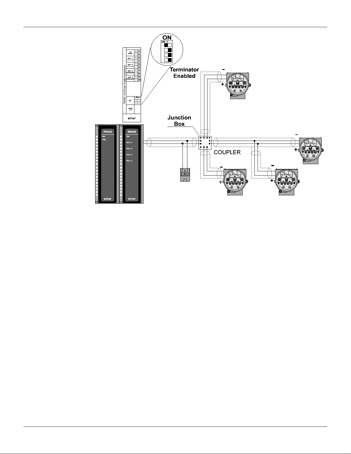
The FI302 uses the 31.25 kbit/s voltage mode option for the physical signaling. All other devices on
the same bus must use the same signaling. All devices are connected in parallel along the same
pair of wires.
Various types of Fieldbus devices may be connected on the same bus.
The FI302 is powered via the bus. The limit for such devices is 12 for one bus for non-intrinsically
safe requirement. In hazardous area, the number of devices may be limited by intrinsically safe
restrictions.

Installation
1.3
Figure 1.3 - Dimensional Drawing and Mounting Positions
WARNING
HAZARDOUS AREAS
In hazardous areas with explosion proof requirements, the covers must be tightened with at least 8
turns. In order to avoid the penetration moisture or corrosive gases, tighten the O’ring until feeling
the O'ring touching the housing. Then, tighten more 1/3 turn (120°) to guarantee the sealing. Lock
the covers using the locking screw.
In hazardous zones with intrinsically safe or non-incendive requirements, the circuit entity
parameters and applicable installation procedures must be observed.
Cable access to wiring connections is obtained by the two conduit outlets. Conduit threads should
be sealed by means of code-approved sealing methods.
Explosion proof, non-incendive and intrinsic safety Factory Mutual certification are standards for
FI302 (See Control Drawing in Appendix A).
Should other certifications be necessary, refer to the certification or specific standard for installation
limitations.
Figure 1.4 - Output Connections

FI302 - Operation and Maintenance Instruction Manual
1.4
Avoid routing signal wiring close to power cables or switching equipment.
The FI302 is protected against reverse polarity, and can withstand ±35 V DC without damage.
NOTE
Please refer to the General Installation, Operation and Maintenance
Manual for more details.
Topology and Network Configuration
Wiring
Other types of cable may be used, other than for conformance testing. Cables with improved
specifications may enable longer trunk length or superior interface immunity. Conversely, cables
with inferior specifications may be used subject to length limitations for trunk and spurs plus possible
nonconformance to the RFI/EMI susceptibility requirements. For intrinsically safe applications, the
inductance/resistance ratio (L/R) should be less than the limit specified by the local
regulatory agency for the particular implementation.
Figure 1.5 - Bus Topology
Installation
1.5
Figure 1.6 - Tree Topology
There are two ways to configure the communication and function block links for the FI302. The first
is using a system configuration device. In this case the heaviest and most difficult task is automated
and the risk for configurating the communication wrongly is almost eliminated. In this system,
addressing of a device is first done using the physical device tag of that device. Before a new (non-
initialized) device is connected to the network it must therefore be configured with this tag.
Connect a configurator to the non-initialized FI302 without having any other devices on the line.
Assign the physical device tag to the FI302.
The FI302 is now initialized and can be connected to the network.
The system will now automatically assign a station address to the FI302, bringing it to its stand-by
state.
The FI302 can now be configured for the application and brought to the operational state.
The second method is manually pre-configured the communication using the local adjustment. This
eliminates the need for a powerful system configurator, but requires more knowledge of the Fieldbus
communication mechanism. This may be a money saving solution in a small system, but hard to do
bug-free in a large system.

FI302 - Operation and Maintenance Instruction Manual
1.6

Section 2
2.1
Operation
Functional Description – Electronics Refer to the block diagram
Figure 2.1 - FI302 Block Diagram
The function of each block is described below:
D/A
Receives the signal from the CPU and converts it to an analog voltage, used by the current control.
Current Control
Controls the current of the channel according the data received from the CPU.
Signal Isolator
Its function is to isolate the data signal between the output and the CPU.
(CPU) Central Processing Unit, RAM and PROM
The CPU is the intelligent portion of the converter, being responsible for the management and
operation of block execution, self-diagnostics and communication. The program is stored in PROM.
For temporary storage of data there is a RAM. The data in the RAM is lost if the power is switched
off, however the device also has a nonvolatile EEPROM where data that must be retained is stored.
Examples of such data are calibration, configuration and identification data.
Communication Controller
It monitors line activity, modulates and demodulates communication signals and inserts and deletes
start and end delimiters.
Power Supply
Takes power of the loop-line to power the converter circuitry.

FI302 - Operation and Maintenance Instruction Manual
2.2
Power Isolation
Just like the signals to and from the output section, the power to the output section must be isolated.
Display Controller
Receives data from the CPU and drives the Liquid Crystal Display.
Local Adjustment
Two switches that are magnetically activated. They can be activated by the magnetic tool without
mechanical or electrical contact.

Section 3
3.1
Configuration
One of the many advantages of Fieldbus is that device configuration is independent of the
configurator. The FI302 may be configured by a third party terminal or operator console. Any
particular configurator is therefore not addressed here.
The FI302 contains three output transducer blocks, one resource block, one display transducer
block and function blocks.
Function Blocks are not covered in this manual. For explanation and details of function blocks, see
the “Function Blocks Manual”.
Transducer Block
Transducer block insulates function block from the specific I/O hardware, such as sensors,
actuators. Transducer block controls access to I/O through manufacturer specific implementation.
This permits the transducer block to execute as frequently as necessary to obtain good data from
sensors without burdening the function blocks that use the data. It also insulates the function block
from the manufacturer specific characteristics of certain hardware.
By accessing the hardware, the transducer block can get data from I/O or passing control data to it.
The connection between Transducer block and Function block is called channel. These blocks can
exchange data from its interface.
Normally, transducer blocks perform functions, such as linearization, characterization, temperature
compensation, control and exchange data to hardware.
How to Configure a Transducer Block
Each time when you select a field device on SYSCON by instantiating on the Operation menu,
automatically you instantiate one transducer block and it appears on screen.
The icon indicates that one transducer block has been created and by clicking twice on the icon, you
can access it.
The transducer block has an algorithm, a set of contained parameters and a channel connecting it to
a function block.
The algorithm describes the behavior of the transducer as a data transfer function between the I/O
hardware and other function block. The set of contained parameters, it means, you are not able to
link them to other blocks and publish the link via communication, defines the user interface to the
transducer block. They can be divided into Standard and Manufacturer Specific.
The standard parameters will be present for such class of device, as pressure, temperature,
actuator, etc., whatever is the manufacturer. Oppositely, the manufacturers specific ones are
defined only for its manufacturer. As common manufacturer specific parameters, we have calibration
settings, material information, linearization curve, etc.
When you perform a standard routine as a calibration, you are conducted step by step by a method.
The method is generally defined as guide line to help the user to make common tasks. The
SYSCON identifies each method associated to the parameters and enables the interface to it.
Terminal Number
The terminal number, which references a channel value, which is sent via internal, manufacturer-
specific from the specified transducer, output to function block.
It starts at one (1) for transducer number one until three (3) for transducer number three.
The channel number of the AO block is related to the transducer’s terminal number. Channel
number 1, 2, 3 corresponds bi-univocally to the terminal block with the same number. Therefore, all
the user has to do is to select combinations: (1.1), (2.2), (3,3) for (CHANNEL, BLOCK).

FI302 - Operation and Maintenance Instruction Manual
3.2
Current Trim
The FI302 provides the capability of making a trim in the output channels, if necessary.
A trim is necessary if the indicator reading of the transducer block output differs from the actual
physical output. The reason may be:
•The user's current meter differs from the factory standard.
•The converter had its original characterization shifted by over-load or by long term drift.
The user can check the calibration of the transducer output by measuring the actual current in the
output and compare it with the device’s indication (of course an appropriate meter should be used).
If a mismatch is detected, a trim can be done.
Trim can be done in two points:
LOWER TRIM: Is used to trim the output at the lower range.
UPPER TRIM: Is used to trim the output at the upper range.
These two points define the linear characteristic of the output. Trim in one point is independent from
the other.
There are two ways of doing the trim: using local adjustment or using SYSCON (the System
Configurator from SMAR). When doing the trim, make sure you are using an appropriate meter (with
the necessary accuracy).
Via SYSCON
Configure in the Transducer, the parameter “TERMINAL_NUMBER” with 1,2, or 3, according to the
“CHANNEL” number of Analog Output block.
Figure 3.1 - Choosing the Output Channel – FI302
In this case the
channel 1 was
choosen.
This parameter
selects the terminal
number which the
output current will be
generated and
calibrated.

Configuration
3.3
It is possible to calibrate the transmitter by means of parameters CAL_POINT_LO and CAL-POINT-
HI.
Let’s take the lower value as an example: write 4 mA or the lower value in parameter
CAL_POINT_LO.
Figure 3.2 - Calibrating the Cal Point Lo – FI302
Always keep in mind that, simply by writing in this parameter, the trim procedure is initialized.
Read the current in the multimeter and write that value in parameter FEEDBACK_CAL. Write in this
parameter until it reads 4.0 mA or the lower value readout of the multimeter.
Figure 3.3 - Feedback of Current Lo Value
This parameter
indicates where the
converter should be
when the setpoint lowe
r
value is 0%.
The desired value
should be entered.
This parameter should
be set with the actual
output current during the
calibration procedure.
The value should be
entered here.

FI302 - Operation and Maintenance Instruction Manual
3.4
In order to end the trim procedure, choice DISABLE in the parameter CAL_CONTROL.
Figure 3.4 - Closing the Calibration Lo Procedure
Let’s take the upper value as an example:
Write 20 mA in parameter CAL_POINT_HI. Always keep in mind that, simply by writing in this
parameter, the trim procedure is initialized.
Figure 3.5 - Calibrating the Cal Point Hi – FI302
This parameter ends
the calibration
procedure.
The enable option indicates
that the calibration process
is being done. In order to
finalize its procedure, the
user should set it to
disable.
This parameter
indicates where the
converter should be
when the setpoint is
100%.
The desired value
should be entered.

Configuration
3.5
Read the current in the multimeter and write that value in parameter FEEDBACK_CAL. Write in this
parameter until it reads 20.00 mA or the upper value readout of the multimeter.
Figure 3.6 - Feedback of Current Hi Value – FI302
In order to end the trim procedure, choice DISABLE in the parameter CAL_CONTROL.
Figure 3.7 - Closing the Calibration Hi Procedure
The value
should be
entered here.
This parameter
should be set with the
actual output current
during the calibration
procedure.
This parameter
ends the calibration
procedure.
The enable option
indicates that the
calibration process is
being done. In order to
finalize its procedure,
the user should set it to
disable.

FI302 - Operation and Maintenance Instruction Manual
3.6
The calibration will be enabled only if the output of AO block has a valid value and status different of
"Bad" In this case, the following message can be seen in the parameter XD_ERROR.
Figure 3.8 - Calibration Error Message – FI302
NOTE
It is convenient to choose the unit to be used in parameter
XD_SCALE of the Analog Output Block, considering that sensor
limits at 100% and at 0% should be observed.
It is also recommendable, for every new calibration, save the
existing trim data in parameters CAL_POINT_LO_BACKUP and
CAL_POINT_HI_BACKUP, by means of parameter
BACKUP_RESTORE, using option LAST_TRIM_BACKUP.
This parameter
indicates de Error Code
Operation associated to
calibration procedure.
It indicates that the
calibration procedure
was not sucessfull.
Other manuals for FI302
1
Table of contents
Other SMAR Power Distribution Unit manuals


Popular Power Distribution Unit manuals by other brands

DVIGear
DVIGear DVI-7520-PDU quick start guide

Compaq
Compaq 207590-B21 - Power Distribution Unit Strip Quick install guide

IP Power
IP Power 9858S S+Ping user manual

Deif
Deif PPU-2 Application notes

Vertiv
Vertiv Liebert TDU-3500RTL620 Quick installation user's guide

Eaton
Eaton Crouse-hinds series instruction manual


