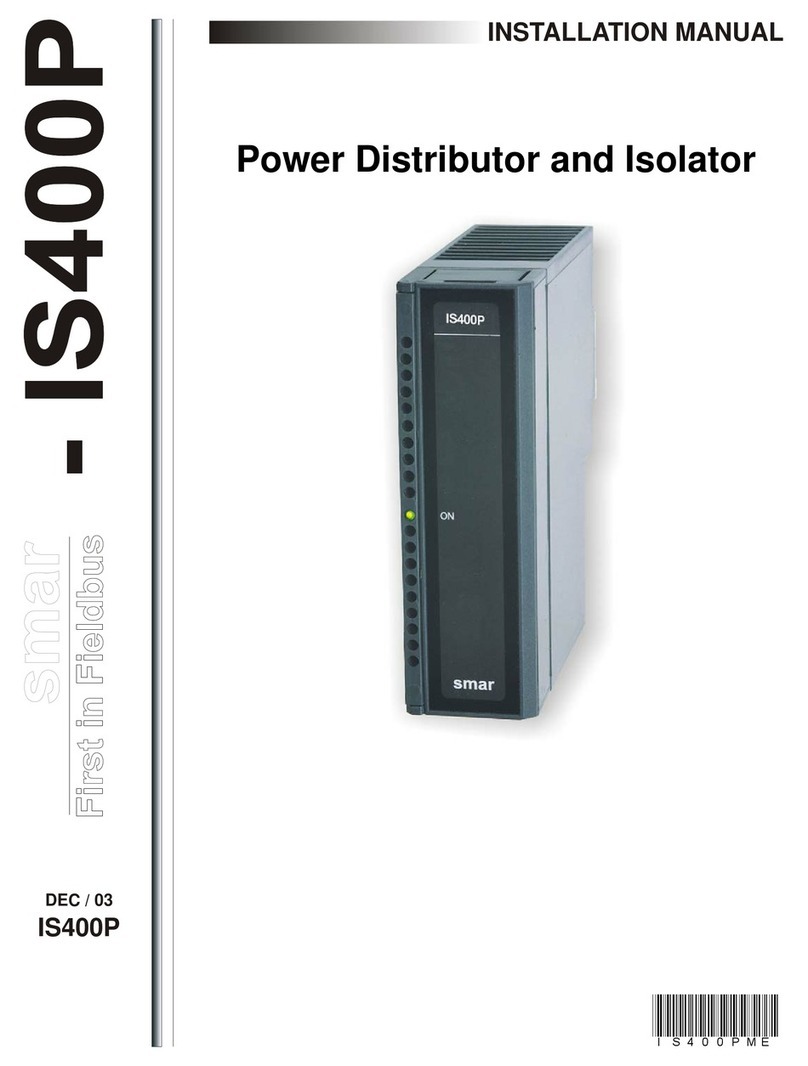
SMAR SI-700-EIA-232 User manual

SI-700
SI-700 - EIA-232/ EIA-485
INTERFACE
SI-700
VERSION 1
FOUNDATION
TM
JUL / 05
USER’S MANUAL
SI 700ME

web: www.smar.com/contactus.asp
www.smar.com
Specifications and information are subject to change without notice.
Up-to-date address information is available on our website.
smar

SI-700 –EIA-232/EIA-485 Interface
1
SI-700 – EIA-232/EIA-485 INTERFACE
Part Number
SI-700 (EIA-232/EIA-485 Interface)
Description
This module converts the electrical characteristics of the communication signal from the EIA-232
specification to the EIA-485 specification. Due to the fundamental differences between the EIA-232
and the EIA-485, the first option EIA-232 is used in peer-to-peer applications) this module was
implemented to work automatically. No control signal is necessary to manage the bus contention on
the EIA-485 side. It is necessary to connect the transmission and reception lines on both sides to
make the interface work.
The converter circuit provides signal isolation to grant a safe connection between two systems. This
module was designed to use the DFI/LC platform. No power supply was embedded in the board. It
uses the +5Vdc lines from the IMB bus to energize the circuit.
Figure 1- SI-700 Interface EIA-232/EIA-485

SI-700 –EIA-232/EIA-485 Interface
2
Interface Settings
There is two interface settings located on the front panel to adapt this interface to the applications:
EIA-232 Mode and EIA-485 Bus Terminator.
- EIA-232 Mode: Half-Duplex/Full-Duplex
The EIA-232 Mode setting adapts the use of EIA-232/EIA-485 Interface to the communication driver
at the EIA-232 side. Normally interfaces of this type connect unidirectional buses with a bi-directional
bus. The unidirectional bus will be able to present the Full Duplex features caused by transmission
message reflection (echo). If the driver used does not treat properly the reception and the
transmissions messages simultaneously, either disabling the reception or discarding the reflected
message, it will be necessary to select the Half-Duplex option. If the reflected message does not
disturb the applications, you can select the Full-Duplex option.
- EIA-485 Bus Terminator: On/Off
The EIA-485 is a Multi-Drop type bus. The transmitter driver is put in the high impedance (Hi-Z) state
when there is no message to transmit. Therefore, the EIA-485 bus requires a bus terminator to
prevent noise problems during the idle state of the EIA-485.
For the proper line impedance matching it is necessary to activate only one terminator by bus. Leave
the other terminators deactivated.
Connectors
There are two connectors on the front panel to interconnect two communication systems. The first,
an RJ12 type connector is used for the EIA-232 systems and the other, a terminal block type
connector is used for the EIA-485 systems.
RJ12 Pin Assignment
Pin Number Description
1 Connected to 6 pin.
2 Not used
3 RxD: EIA-232 input signal - reception
4 TxD: EIA-232 output signal - transmission
5 GND: EIA-232 signal ground
6 Connected to 1 pin
Note: Pins 1 and 6 are interconnected to allow the handshaking between the modem signals when
required by communication drivers, such as Clear-To-Send (CTS) with Request-To-Send (RTS)
interconnection.
Pin Block Terminal
Pin Number Description
1 +: EIA-485 Non inverting signal
2 -: EIA-485 Inverting Signal
3 GND: Reference for EIA-485 Communication Signal.
NOTE
The GND pin is used to set up a voltage reference for all EIA-485 nodes, on the same bus. The
EIA-485 side of EIA-232/EIA-485 Interface is isolated and is left in a floating state. To avoid
undesirable high common mode voltage it is recommended to make all of the EIA-485 nodes on
the same voltage reference by connecting all GND pins and grounding at just one point.

SI-700 –EIA-232/EIA-485 Interface
3
Cabling and Applications
For each application, Smar also produces a set of cables to be used accordingly. See the
specifications below.
Technical Specifications
Number of Communication Channels 1
Data Communication Interface EIA-232 / EIA-485
Baud rate Up to 200 Kbps enable
EIA-232 side Enables EIA-232 Half-Duplex or Full-
Duplex mode
EIA-485 side Enables Embedded Bus Terminator
activation
Protection EIA-485 No transmission when the bus is in
break state.
Isolation 1600 VRMS @1 minute, typical
Power Supply Supplied by the IMB bus, +5 Vdc, @
100 mA, typical
NOTE
In the interconnection of the 485 network, to attend the EMC standard (Electromagnetic capability), it is
necessary to use a 3-wire shielded twisted pair cable. Where, two wires are used to communication and
the third is used as reference. The shielding must be connected in one of the housing endings.

SI-700 –EIA-232/EIA-485 Interface
4
Installing the Module in the Rack
Follow the steps below to install the module in the rack.
Mounting a module in the rack:
oFind the border located
at the top of the free
slot.
oFit the hole, at the top
back of the module.
Mounting detail.
Lock the module in the connector
(slot) of the IMB by pushing it
against the rack.
Next, fix the module at the rack
using a screw driver, and fix the
locking screw at the bottom of the
module.

Appendix A
A.1
SRF – Service Request Form
smar SI700 Proposal Nº:
COMPANY INFORMATION
Company:
_____________________________________________________________________________________________________
Unit/Department:___________ _____________________________________________________________________________________
Invoice:______________ ________________________________________________________________________________________
COMMERCIAL CONTACT
Full Name:______
_______________________________________________________________________________________________
Phone:___ _________ _________________________ _________ _________________________ Fax: _______________________
Email: _______________________________________________________________________________________________________
TECHNICAL CONTACT
Full Name: _____________________________________________________________________________________________________
Phone: _________ _________________________ _________ _________________________ Extension: _______________________
Email: _______________________________________________________________________________________________________
EQUIPMENT DATA
Model:
______________________________________________________________________________________________________
Serial Number: _______________________________________________________________________________________________
PROCESS DATA
Process Type: _________________________________________________________________________________________________
Operation Time: ________________________________________________________________________________________________
Failure Date: ___________________________________________________________________________________________________
FAILURE DESCRIPTION
(Please, describe the observed behavior, if it is repetitive, how it reproduces, etc.)
______________________________________________________________________________________________________________
______________________________________________________________________________________________________________
______________________________________________________________________________________________________________
______________________________________________________________________________________________________________
OBSERVATIONS
______________________________________________________________________________________________________________
______________________________________________________________________________________________________________
______________________________________________________________________________________________________________
USER INFORMATION
Company: _____________________________________________________________________________________________________
Contact: ______________________________________________________________________________________________________
Title: _________________________________________________________________________________________________________
Section:_________________________________________________________________________________________________________
Phone: _________ _________________________ _________ _________________________ Extension: ___________________
E-mail: ________________________________________________________________________ Date: ______/ ______/ _________
For warranty or non-warranty repair, please contact your representative. Further information about address and contacts can be found on
www.smar.com/contactus.asp.

SI-700 –EIA-232/EIA-485 Interface
A.2

Appendix B
B.1
SMAR WARRANTY CERTIFICATE
1. SMAR guarantees its products for a period of 24 (twenty four) months, starting on the day of
issuance of the invoice. The guarantee is valid regardless of the day that the product was
installed.
2. SMAR products are guaranteed against any defect originating from manufacturing, mounting,
whether of a material or manpower nature, provided that the technical analysis reveals the
existence of a quality failure liable to be classified under the meaning of the word, duly verified
by the technical team within the warranty terms.
3. Exceptions are proven cases of inappropriate use, wrong handling or lack of basic maintenance
compliant to the equipment manual provisions. SMAR does not guarantee any defect or
damage caused by an uncontrolled situation, including but not limited to negligence, user
imprudence or negligence, natural forces, wars or civil unrest, accidents, inadequate
transportation or packaging due to the user’s responsibility, defects caused by fire, theft or stray
shipment, improper electric voltage or power source connection, electric surges, violations,
modifications not described on the instructions manual, and/or if the serial number was altered
or removed, substitution of parts, adjustments or repairs carried out by non-authorized
personnel; inappropriate product use and/or application that cause corrosion, risks or
deformation on the product, damages on parts or components, inadequate cleaning with
incompatible chemical products, solvent and abrasive products incompatible with construction
materials, chemical or electrolytic influences, parts and components susceptible to decay from
regular use, use of equipment beyond operational limits (temperature, humidity, etc.) according
to the instructions manual. In addition, this Warranty Certificate excludes expenses with
transportation, freight, insurance, all of which are the customer’s responsibility.
4. For warranty or non-warranty repair, please contact your representative.
Further information about address and contacts can be found on www.smar.com/contactus.asp
5. In cases needing technical assistance at the customer’s facilities during the warranty period,
the hours effectively worked will not be billed, although SMAR shall be reimbursed from the
service technician’s transportation, meals and lodging expenses, as well dismounting/mounting
costs, if any.
6. The repair and/or substitution of defective parts do not extend, under any circumstance, the
original warranty term, unless this extension is granted and communicated in writing by SMAR.
7. No Collaborator, Representative or any third party has the right, on SMAR’s behalf, to grant
warranty or assume some responsibility for SMAR products. If any warranty would be granted
or assumed without SMAR’s written consent, it will be declared void beforehand.
8. Cases of Extended Warranty acquisition must be negotiated with and documented by SMAR.
9. If necessary to return the equipment or product for repair or analysis, contact us.
See item 4.
10. In cases of repair or analysis, the customer must fill out the Revision Requisition Form (FSR)
included in the instructions manual, which contains details on the failure observed on the field,
the circumstances it occurred, in addition to information on the installation site and process
conditions. Equipments and products excluded from the warranty clauses must be approved by
the client prior to the service execution.
11. In cases of repairs, the client shall be responsible for the proper product packaging and SMAR
will not cover any damage occurred in shipment.

SI-700 –EIA-232/EIA-485 Interface
B.2
12. In cases of repairs under warranty, recall or outside warranty, the client is responsible for the
correct packaging and packing and SMAR shall not cover any damage caused during
transportation. Service expenses or any costs related to installing and uninstalling the product
are the client´s sole responsibility and SMAR does not assume any accountability before the
buyer.
13. It is the customer’s responsibility to clean and decontaminate products and accessories prior to
shipping them for repair, and SMAR and its dealer reserve themselves the right to refuse the
service in cases not compliant to those conditions. It is the customer’s responsibility to tell
SMAR and its dealer when the product was utilized in applications that contaminate the
equipment with harmful products during its handling and repair. Any other damages,
consequences, indemnity claims, expenses and other costs caused by the lack of
decontamination will be attributed to the client. Kindly, fill out the Declaration of
Decontamination prior to shipping products to SMAR or its dealers, which can be accessed at
www.smar.com/doc/declarationofcontamination.pdf and include in the packaging.
14. This warranty certificate is valid only when accompanying the purchase invoice.
This manual suits for next models
1
Table of contents
Other SMAR Power Distribution Unit manuals
