smart acoustic TRANSPORTA 10 User manual

TRANSPORTA 10 |TRANSPORTA 12
Portable Professional Audio
USER MANUAL
www.smart-acoustic.com

USING THE UNIT SAFELY
INSTRUCTIONS
A
A
A

A
A
A
A
A
USING THE UNIT SAFELY
AS OBSEE THE FOLLOWING
A
A
A
A

USING THE UNIT SAFELY
AS OBSEE THE FOLLOWING
Power Supply: Use of Batteries
Placement
Maintenance
Additional Precautions
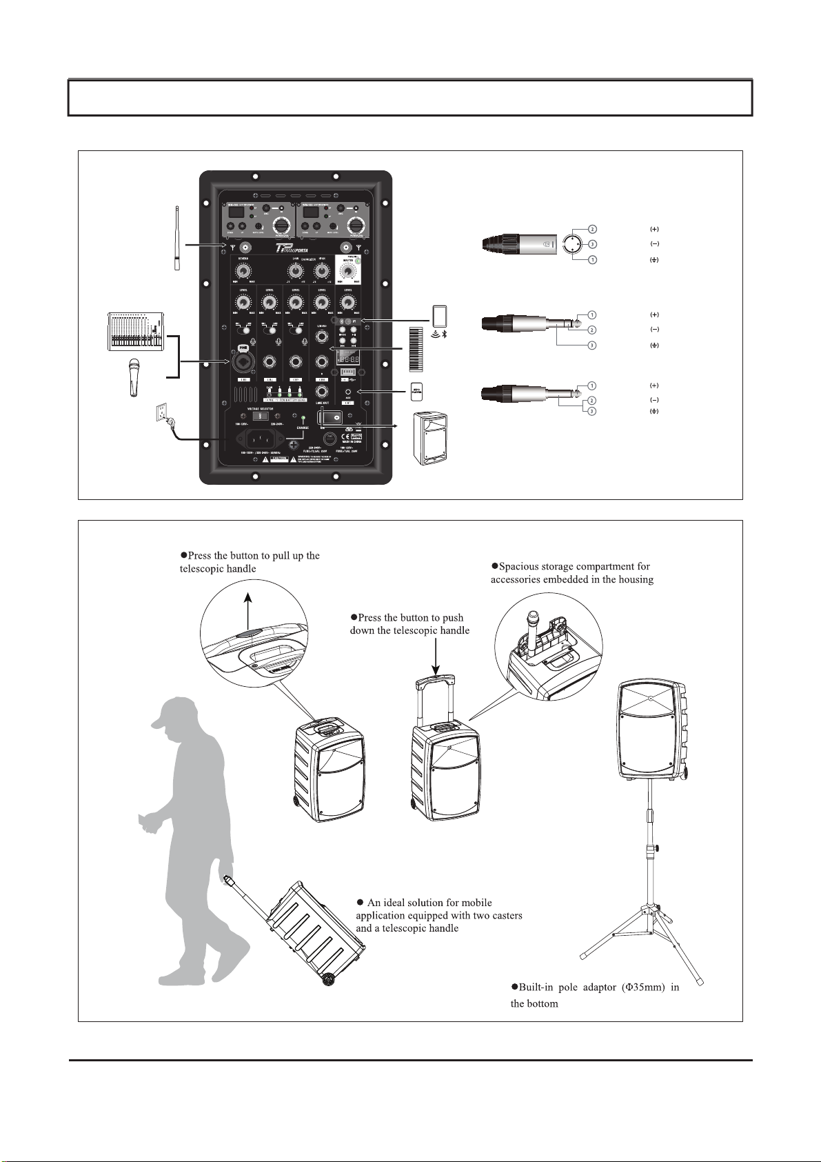
MIC-REVERB:
WIRELESS MIC
CH1-CH3
TP12=250W
MASTER
XLR
TRS
TS
sleeve - ground
tip - hot
ring - cold
ground
tip - hot
cold
ground
hot
cold
TRANSPORTA 10 / TRANSPORTA 12 FEATURES

MIC-REVERB:
WIRELESS MIC
CH1-CH3
TP12=250W
MASTER
1
27
4
5
6
6
18
8
3 5
7 29
9
10
12
13
14
15
17
16
11
4
2
3
18
19
20
22
24
21
23
26
25
7
TRANSPORTA 10/12 PANEL DESCRIPTION

TRANSPORTA 10/12 PANEL DESCRIPTION
1. Channel Display
2. DOWN: Down button for selecting
Radio Transmission Channel.
3. UP: Up button for selecting
Radio Transmission Channel.
4. RF: RF Indicator light
5. AF: AF Indicator light
6. Mute level: Mute adjust minimum
signal strength.
7. ASC: Auto frequency
8. Power-vol:
Power switch on/off and volume adjust
9. IR window:
Infrared transmitter for transmitting channel
settings from the device to the microphone.
10. EQ Controller Knobs
Controller for adjusting the high and low
frequency in a range of [-12] ... [ + 12]dB.
on the master channel.
11. PWR/LIM
This LED lights blue in normal operation and
red when the speaker is over driven (clipping).
Note: When in normal operation, the LED
may flash red, but if continuously red will
do harm to the device.
12. MASTER (Main Volume Knob)
Adjusts the total system volume.
13. Remote Control Window
Use the supplied remote control to
control this device.
14. INTERNAL MULTIFUNCTION PLAYER
Internal multifunction player contains
BLUETOOTH, USB and AUX INPUT.
Press the MODE button to select
different sound source input.
15. Power Switch
This is the On/Off switch.
If not using the unit, please switch to OFF.
16. LINE OUT
TRS (balanced) output to connect a PA or an
additional powered speaker. The output volume
is controlled by this unit.
17. FUSE
Specification: T2.5AL/250V
18. REVERB Knob
Controls Reverb for wireless and CH 1, 2 & 3
19. Volume Knob
Volume control for CH1/CH2/CH3/CH4/CH5
20. LINE/MIC switch
Switch between LINE and MIC input signal level.
21. CH4 (L/MONO,R)
TS (unbalanced) input connector
22. CH1
XLR or TRS (balanced) input connector
23. CH2 /CH3
Signal input for CH2/CH3
24. Battery Level
State of charge indicators. All four LEDs light
when batteries are fully charged. When capacity
decreases, the green LEDs 3,2,1 go out one
by one. If only the red LED lights the remaining
battery capacity is low. Then connect the device
to the mains power to charge the batteries.
25. CHARGE
This LED lights during charging. Once the
installed battery pack is fully charged,
the LED turns off.
26. IEC Power Socket
Once the unit is connected to the mains,
the built-in rechargeable batteries are being
charged even when the power is off.
27. Antenna A + B Connector for
wireless modules.
The mode button can choose USB/AUX/BT.
The USB connector can’t provide charging.
When choosing AUX you can play music by
connecting a 3.5mm Jack; when choosing
BT you can connect a signal into the device by:
Selecting Bluetooth device name. TRANSPORTA
10 / TRANSPORTA 12
In USB or BT mode, the button will
pause or play.
In USB or BT mode, the button will skip to
the previous song, press for 3 seconds to reduce
volume.
In USB or BT mode, the button will skip to
the next song, press for 3 seconds to add volume.

Specifications:
Max Audio input level: 0dBV
Dimensions: 250*54mm dia.
Weight: 270 grams (without batteries)
Power Requirements:
2 “AA” size alkaline or rechargeable batteries
Battery Life: >8 hours
Specifications:
Sensitivity: <15dbu
AF output level: 500mV
Harmonic Suppression: >30db
THD: <1%
Power supply: 11-15V
+
Channel Display shows radio transmission Channel 01-16
Down/Up: Push button for selecting the radio transmission channel.
Proceed as follows to find a free channel:
• Turn off the radio microphone (transmitter) and the receiver
(with the controller [POWER-VOL] ).
• Navigate through the available channels by clicking [Down/Up]
If the displayed channel is already in use, the red LED [RF] lights up.
The first and (if applicable) second radio receiver must be turned to a different channel.
The red display LED [RF] lights up when a radio signal is
transmitted between the microphone and receiver.
The green LED [AF] lights up when an audio signal from
an external device is present.
Mute level: mute adjust control to set the minimum signal
strength on the radio transmission channel.
ASC: Auto frequency. Press this button to transfer the channel setting
from the device via the infrared port to the microphone.
Power-vol: Power switch off for turn off and volume adjust.
IR Window: Infrared transmitter for transmitting the channel setting
from the device to the microphone.
Microphone head grill to prevent damage
and to reduce wind and breath noise.
Adjust input sensitivity decrease, turn left for
sensitivity decrease. turn right for sensitivity increase.
RF Power Switch: Switch for selecting the transmission
level. In ‘L’ Position, a low level is used to save the
batteries. As a result the range is reduced. In ‘H’ position,
a high level is used for an expanded transmission range.
This reduces battery life.
Infrared sensor for receiving the channel setting from the
device to the microphone. The sensor is accessible after
the removal of the lower housing part. After each change,
transfer the channel setting from the device to the
microphone. Place the microphone as close as possible to
the device and then press [ASC]. The LED [RF] lights up if
the transmission was successful.
Batteries compartment for 2 AA cell (LR6, 1.5v)
or appropriate rechargeable batteries.
Power/ASC Battery low indicator light.
Green on: Power on
Green Flash: IR transmission in process.
Red Flash: Battery low
ON-Off/Mute switch
Functions:

Specifications:
Max Audio input level: 0dBV
Dimensions: 250*54mm dia.
Weight: 270 grams (without batteries)
Power Requirements:
2 “AA” size alkaline or rechargeable batteries
Battery Life: >8 hours
Specifications:
Sensitivity: <15dbu
AF output level: 500mV
Harmonic Suppression: >30db
THD: <1%
Power supply: 11-15V
+
Channel Display shows radio transmission Channel 01-16
Down/Up: Push button for selecting the radio transmission channel.
Proceed as follows to find a free channel:
• Turn off the radio microphone (transmitter) and the receiver
(with the controller [POWER-VOL] ).
• Navigate through the available channels by clicking [Down/Up]
If the displayed channel is already in use, the red LED [RF] lights up.
The first and (if applicable) second radio receiver must be turned to a different channel.
The red display LED [RF] lights up when a radio signal is
transmitted between the microphone and receiver.
The green LED [AF] lights up when an audio signal from
an external device is present.
Mute level: mute adjust control to set the minimum signal
strength on the radio transmission channel.
ASC: Auto frequency. Press this button to transfer the channel setting
from the device via the infrared port to the microphone.
Power-vol: Power switch off for turn off and volume adjust.
IR Window: Infrared transmitter for transmitting the channel setting
from the device to the microphone.
Microphone head grill to prevent damage
and to reduce wind and breath noise.
Adjust input sensitivity, turn left for
sensitivity decrease. turn right for sensitivity increase.
RF Power Switch: Switch for selecting the transmission
level. In ‘L’ Position, a low level is used to save the
batteries. As a result the range is reduced. In ‘H’ position,
a high level is used for an expanded transmission range.
This reduces battery life.
Infrared sensor for receiving the channel setting from the
device to the microphone. The sensor is accessible after
the removal of the lower housing part. After each change,
transfer the channel setting from the device to the
microphone. Place the microphone as close as possible to
the device and then press [ASC]. The LED [RF] lights up if
the transmission was successful.
Batteries compartment for 2 AA cell (LR6, 1.5v)
or appropriate rechargeable batteries.
Power/ASC Battery low indicator light.
Green on: Power on
Green Flash: IR transmission in process.
Red Flash: Battery low
ON-Off/Mute switch
Functions:


SUPPORT and TROUBLESHOOTING
No sound om
the loudspeaker c.
Loudspeaker has
hum or buzz
Remote control
does not work
R
No sound om
the Microphone
Screaming, noise,
distorted sound
om the Mic
No sound connect
to bluetooth
;

TP10 TP12
This manual suits for next models
1
Table of contents