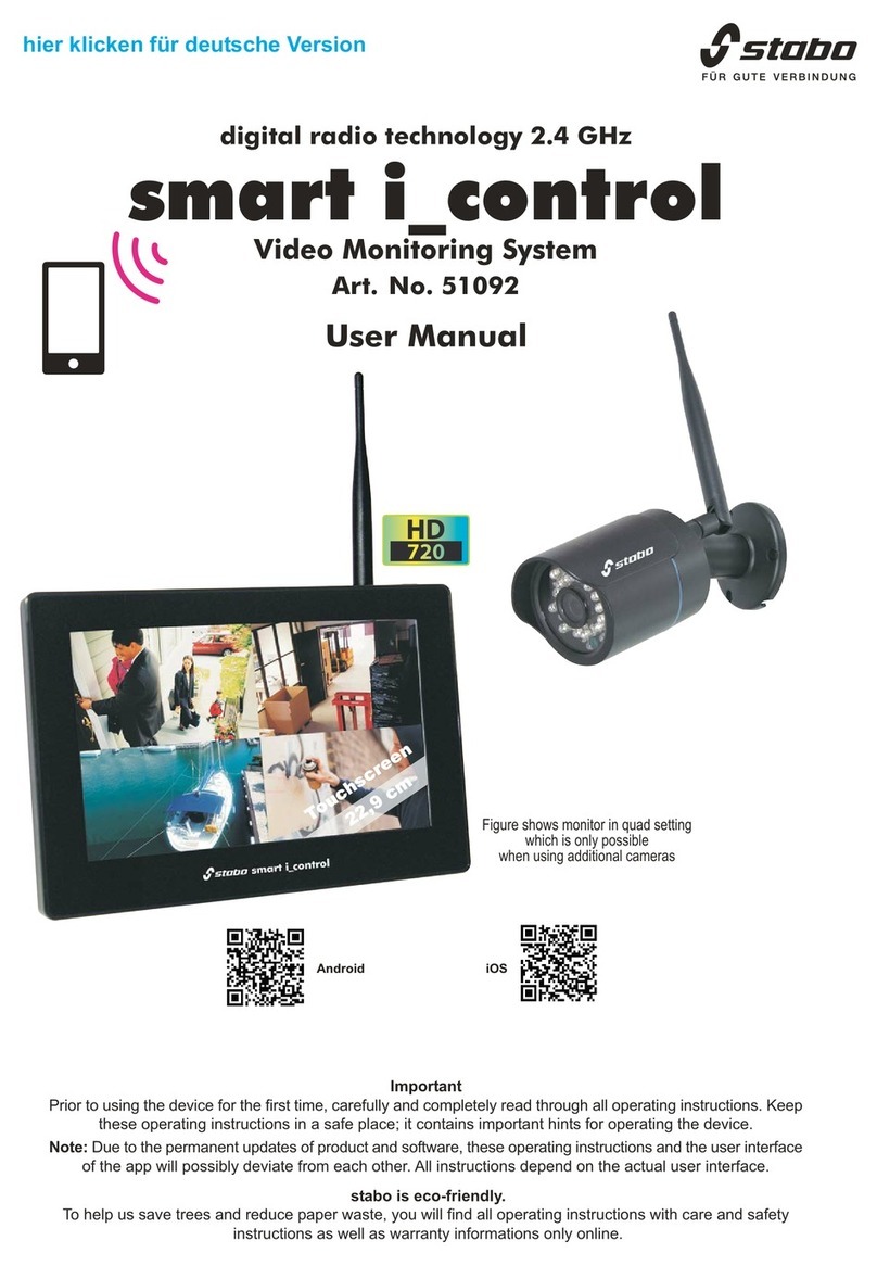
Smart Park CCS704WHD User manual


Page 2
Product Overview
The CCS704WHD represents a combination of the highest quality
camera and LCD components, combined with the most advance digital
wireless communication technology available.
The system operates at 2.4GHz. It uses Coded Differential Orthogonal
Frequency Division Multiplexing (CDOFDM) technology to provide the
highest quality, most secure, most reliable wireless signal available.
The camera and LCD are paired together and the image from the
camera can only be received on the paired monitor.
The system is suitable for virtually all automotive applications including
passenger, commercial and agricultural applications.
Features and Specification
7’’ IPS-LCD color monitor with HD 1280 x 720P high resolution
display
Expandable 4/2/1 channel camera input
wireless range of up to 400m transmission distance (line of slight)
Automatic pairing function of monitor & camera(s)
Night-vision function (6pcs White/Bright LED)
7’’ monitor with inbuilt DVR
SD card data storage/record
Quad, split or single screen display
Mirror and normal image switch available
Adjustable parking guidelines
Built-in microphone and sound capability
HD720P high resolution, wide angle lens
Firm structure: aluminum alloy housing, anti-UV surface painting
(Camera)
Waterproof: IP68 (Camera)
Angle adjustable
Two years’ warranty

Page 3
Features & Specification
LCD701WHD
Monitor size 7.0’’ IPS-LCD monitor
Transmission frequency 2.4GHz (digital)
Transmission resolution High definition
Transmission delay (ave) < 200mS
RF pairing Auto
Changeable channel 125CH (overlapping hopping channel)
Video frame rate 25fps / 30fps
Operating voltage DC 9V-36V
Consumption < 5.5W
Brightness 500cdm
Mirror image Yes (via menu select)
Speaker Yes
Contrast / Brightness Yes
Camera selection 1-4 (auto or manual)
Dimensions (without sunshade) 185W x 128H x 26D mm
Weight 340g
Operating temperature -20℃+ 70℃
CAM150WHD
Image device: 1/3.7’’ CMOS BSI 1280Hx960V pixel
Scanning system PAL & NTSC
Video frame rate 25fps / 30fps
Operating voltage DC 9V-36V
Consumption (IR LED on) < 2.5W
Lens angle 130degree diagonal
Microphone Yes
White/Bright LED 6 (10m visibility)
White/Bright LED switch control Photo sensor automatic control
Housing Aluminum alloy
Mechanical vibration 10G
Mounting Permanent tilt bracket
Weight 430g
Operating temperature -40℃to +85℃
Ingress protection IP68

Page 4
Required Tool List Supplied Parts list
Screwdrivers Wireless camera with power cable
Marker pencil Wireless monitor with wiring harness
Drill Monitor stand
Plyers Monitor sunshade
Panel removal tool Installation screws/clips
Soldering iron & solder Antenna rubber stoppers
Voltmeter
Safety Glasses
Set Antenna & Rubber Stopper
This procedure can be used for both the camera and LCD:
1. Screw antenna on the base
2. Align antenna to allow it to point straight up.
3. Adjust antenna as desired. It is recommended that antenna be aligned
straight up for best reception.

Page 5
Camera Installation
The CAM150WHD Camera installation is simply a matter of bolting the
camera onto the vehicle and supplying reverse power (DC 9V-36V). The only
issue to take into account is mounting location. There are 3 main factors to
consider:
1.Wireless Performance – The wireless communication cannot pass through
metal so it is always better to try and install the camera near the top of truck or
as low as possible so that the signal can effectively travel over the top or
under the vehicle.
2.Viewing Angle – The primary goal of the installation is to ensure the driver
has a complete view of the area behind the vehicle.
3.Protection – In harsh environments please ensure the hardware is
adequately protected from bangs/knocks or the elements.
LCD Monitor Installation
The LCD monitor requires accessory (ignition) power (DC 9V-36V). The only
issue to take into account is mounting location. There are 2 main factors to
consider:
1.Access and Visibility – Ensure the driver can clearly see the screen and
reach the controls.
2.Antenna Location – The wireless system will perform better if the antenna is
pointed upward and is above the height of the window sills – this allows the
wireless signal to transmit through the window glass directly.
Choose mounting location of the LCD monitor.
Attach the surface mounting bracket to the vehicle body using the supplied
mounting screws or bolts.
Adjust the angle of the monitor and fasten the screws firmly.

Page 6
Operation Instruction
1
2 3 4 5
Button 1: System functionality setting MENU
Button 2: Selection/adjustment down
Button 3: Selection/adjustment up
Button 4: Record-Pause (Normal) / Setting enter (Menu)
Button 5: System power ON-OFF / CAM-CH selection

Page 7
To enter the system menu interface power on the screen, press the “MENU”
button and use the “ ” or “ ” button to move the cursor to the required
sub menu. Press the REC / ENT button to enter the selected sub menu.
1. System Pairing
The purchased set will have been ‘paired’ during the assembly process so the
initial operation should be as simply as power on the system monitor and
camera. If for any reason the camera/ monitor combination needs to be
changed then the system will need to be paired again, the pairing process is
as follows:
a) Using the CAM-CH button select the CAM-CH input to be paired e.g.
CAM1.Confirming the camera is powered off select the “PAIRING” icon
to enter pairing mode. During the visible countdown of 20 seconds,
power on the camera. The system will automatically pair and be
displayed. This system can expand up to 4 cameras, requiring
individual pairing. Repeat the above procedure to pair additional
cameras.
b) Once the system is paired then it will remain paired (with or without
power) until the pairing process is done again.

Page 8
2. Picture setting
Select the “PICTURE” icon to enter the sub-menu setting interface a
shown, then select and adjust the brightness, contrast, saturation and
guideline feature.
3. Mirror-FLP
Select the “MIR-FLP” icon to enter the sub-menu setting interface as
shown, choose and select the correct mode. When used as a backup
camera the image is MIRRORED, this is the default configuration. If the
camera is not used for reversing, then the imager must be switched to
NORMAL mode.
4. Display mode
Select the “MODE” icon to enter the sub-menu setting interface as shown,
choose and select the required display mode combination.

Page 9
5. CAMERA SETUP
Select the “CAM-SETUP” to enter the sub-menu setting interface as shown.
Choose and select the 4 cameras’ ON-OFF status, scan time and auto scan.
The auto scan feature will continuously loop the picture display of multiply
cameras. The cycling time interval displays can be adjusted using the scan
time feature.
6. System
Select the “SYSTEM” icon to enter the sub-menu settings interface as
shown. Adjust the time/date, language, color system, auto dim, delay time
and volume settings.
7. Play
Select the “PLAY” icon to enter the playback interface. Select the dated
folder to playback the recorded SD card (not supplied) content. This feature
will not function unless an SD card (not supplied) is inserted.

Page 10
8. Record
Select the “RECORD” icon to enter the sub-menu setting interface as
shown. Choose and select the rewrite and format settings. The initial use of
a new SD card (not supplied) must be formatted prior to using the record
feature. To use the record feature, select the CAM-CH to be recorded e.g.
CAM1or for multiply CAM recording select the CAM-CH display mode
combination e.g. CAM1/CAM2. When the displayed CAM-CH is shown on
monitor press the REC / ENT button to start recording (note the REC icon
on top of screen). Press the REC / ENT button again to pause recording.
Note: the record feature will not record if the monitor is powered off.
Trouble Shooting
If for any reason the system does not function, firstly confirm that both the
camera and monitor have power (check fuses of power cables).
Note the monitor screen has a small blue power activation light on the front.
If the communication is too weak to send an image you will see:
In each instance follow the pairing guide with the camera and monitor in line of
sight (or as close together as possible).

Page 11
Wiring Diagram

Page 12
FCC Declaration of Conformity
This device complies with Part 15 of the RCC rules. Operation is
subject to the following conditions, (1) this device may not cause
harmful interference and (2) this device must accept any interference
received, including interference that may cause undesired operation.
This equipment generates, uses, and can radiate radio frequency
energy. If not installed and used in accordance with the instructions,
the product may cause disruptive interference to radio communications.
However, there is no guarantee that interference will not occur in a
particular installation. If this equipment does cause harmful interference
to radio or other equipment reception, which can be determined by
turning the equipment off and on, the user is encouraged to try to
correct the interference by one or more of the following measures:
Reorient of relocate the receiving antenna.
Increase the separation between the equipment and receiver.
Connect the equipment to a different power source from the receiver.
Consult the dealer or an experienced radio technician for help.
Changes or modifications not expressly approved by the party
responsible for compliance could avoid the user’s authority to operate
the equipment
This equipment complies with FCC radiation exposure limits set forth
for an uncontrolled environment. This transmitter must not be co-
located or operating in conjunction with any other antenna or
transmitter.
This equipment should be installed and operated with minimum
distance 20cm between the radiator&your body.

Page 13
Smart Park® Warranty Card
PLEASE MAIL OR FAX THIS PAGE TO:
Att: PERFORMANCE GUARANTEE DEPT.,
International Fax #: +61-2-9437-4555
PO Box 124
Spit Junction NSW 2088
Australia
Section 1: VEHICLE INFORMATION
VEHICLE IDENTIFICATION NUMBER: ______________
YEAR MODEL _________________________________
MAKE LICENSE PLATE #: ________________________
PRODUCT SERIAL #: ____________________________
Section 2: PURCHASE INFORMATION
DEALER NAME _________________________________
DATE OF SALE _________________________________
PURCHASE PRICE ______________________________
BUYER’S NAME ________________________________
Section 3: LIMITED WARRANTY
The Smart Park™ product is guaranteed to be free from
mechanical defects for a period of three years when installed by
an authorized Dealership.

Page 14
Table of contents
