stabo Smart i_control 51092 User manual

User Manual
digital radio technology 2.4 GHz
smart i_control
Video Monitoring System
Art. No. 5 092
22,9 cm
Touchscreen
Android iOS
hier klicken für deutsche Version
Important
Prior to using the device for the first time, carefully and completely read through all operating instructions. Keep
these operating instructions in a safe place; it contains important hints for operating the device.
Note: Due to the permanent updates of product and software, these operating instructions and the user interface
of the app will possibly deviate from each other. All instructions depend on the actual user interface.
stabo is eco-friendly.
To help us save trees and reduce paper waste, you will find all operating instructions with care and safety
instructions as well as warranty informations only online.
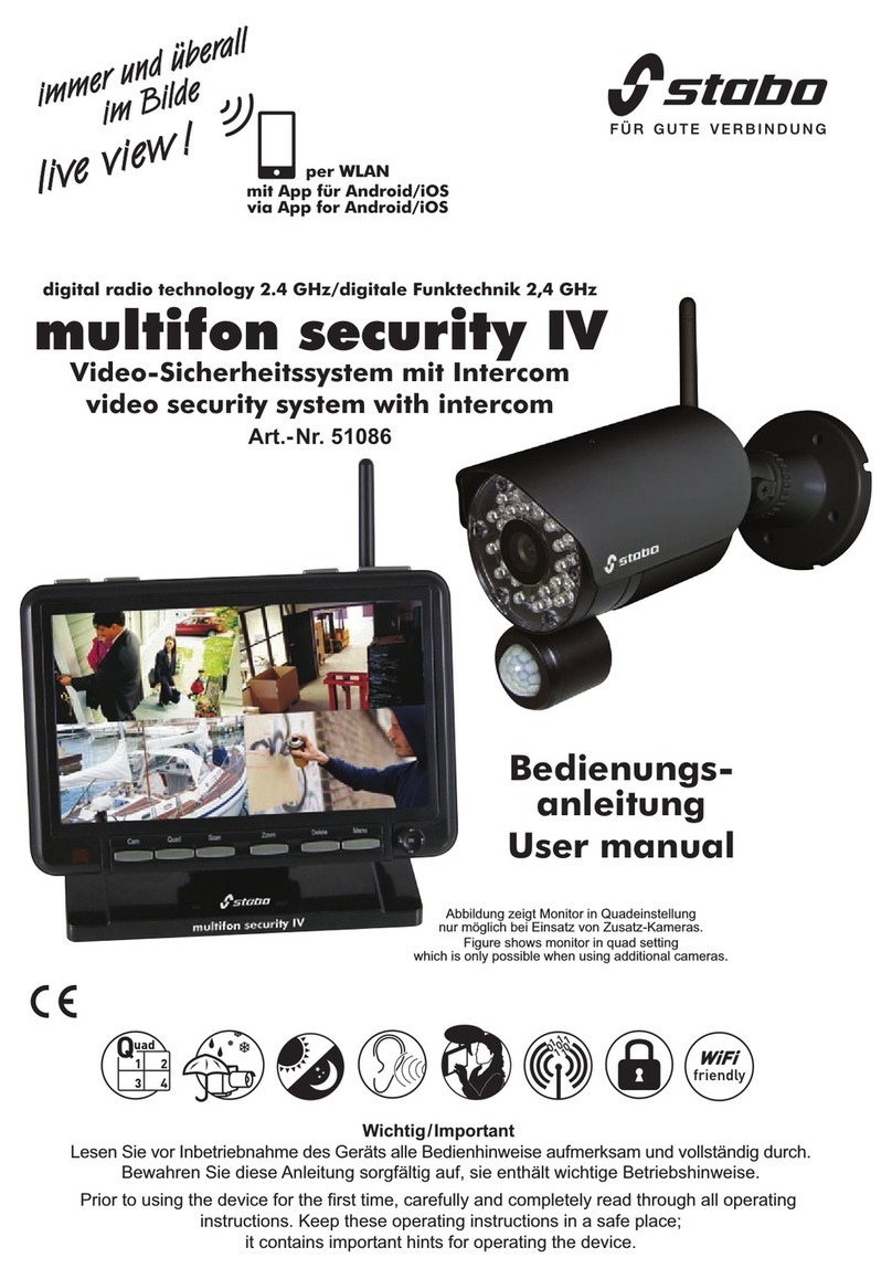
Figure shows monitor in quad setting
which is only possible
when using additional cameras

roduct description/ Intended use
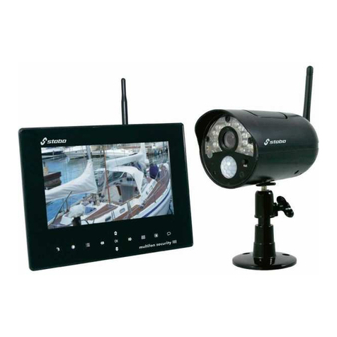
The weatherproof color camera of the stabo smart i control wirelessly transmits video and audio signals of the
monitored area to the monitor. Its digital technology is used to assure a transmission which is almost free from
interferences and secure against eavesdropping thus protecting your privacy.
You can either keep the monitored area in permanent view via the monitor or have the camera images displayed
only, the Video Motion Detection function detects movements. The area detection feature offers the possibility
of restricting motion detection to predefined areas. This prevents triggering of a an alarm in undefined areas.
Thanks to powerful infrared LEDs, image transmission is also possible with poor lighting conditions (in this case,
the monitor image is shown in black and white).
Using the app Kalay Cam (to be obtained free of charge in your App Store or via Google Play), you can use
your smartphone/tablet PC to view live images from your cameras and listen to surrounding sounds (provided
that the monitor has an Internet connection).
The monitor is equipped with a HDD port. Thus, camera shots can be recorded using a commercially available
hard disc up to 2 TB (not included in the scope of supply). A micro SD card slot for cards up to 32 GB is integrated
in the device (card not included).
The stabo smart i control set can be extended: Up to 4 cameras can be connected (additional cameras can
be obtained as option from specialist dealers).
Some of the menu items and functions described within these operating instructions refer to the usage of the
set with several cameras (e.g. quad function)!
Safety notes and warnings
Observe the legal provisions on video surveillance! Make sure that neither neighboring private property
nor adjacent public areas are covered! For commercial areas, it is essential to observe the corresponding
information duty!
Do not expose the system to the weather in the open! The camera of the stabo smart i control is weatherproof
(protection type IP 66) and suitable for mounting in outdoor areas. However, the camera's power supply unit
has to be protected against humidity and moisture!
Monitor and power supply unit are exclusively designed for indoor operation!
Never use the monitor in rooms which are very humid or exposed to dust (e.g. bathroom and/or joinery). Install
the monitor such that tilting and falling is prevented, protect the device against strong vibrations.
Do not use du ring thunderstorms! Do not use the devices during thunderstorms! Disconnect the devices
form the mains when a thunderstorm approaches and/or when you are absent.
The devices must be kept out of the reach of children! Prevent children from playing with the devices,
accessories or the packing material!
Do not use in hospitals and/or nursing facilities! Your stabo smart i control produces radio waves which
might affect the proper functioning of the hospital equipment. If necessary, contact the responsible personnel
to clarify whether safe commissioning is possible.
Do not open the devices or make any modifications to them! Never open parts of the housing and do not
make any modification on the devices. Otherwise, no further guarantee claim can be accepted and the devices
could lose their approval for use!
If the housing is damaged, disconnect the power plug! Immediately disconnect the device from the mains,
if damage on the housing is found. Ensure that possibly required repairs are performed by a qualified person
only
Scope of delivery
22,9 cm (9) color LCD Touchscreen monitor with photo frame bracket
WLAN wireless color camera (IP 66) with mounting bracket (ceiling/wall fastening)
power supply for monitor 12 V/2 A, power supply for camera 5 V/2 A
RJ45 network cable
quickstart user manual DE/EN
Please check the contents of the package for completeness. Prior to using the device, examine it with respect
to any external damage. In case of an external damage, do not put the product into operation, but contact your
specialist dealer immediately.

-2-
1. PRODUCTS OVERVIEW............................................................................................................................................3
1.1 9 inch Touch Screen NVR.........................................................................................................3
1.2 Bracket ( Optional ) ....................................................................................................................3
1.3 Camera ..........................................................................................................................................4
2. HARD DISK INSTALLATION.................................................................................................................................... 4
3. SPECIFICATION..........................................................................................................................................................4
4. QUICK SETUP.............................................................................................................................................................6
4.1 Connect the 9 inch NVR...............................................................................................................6
4.2 Connect the Camera..................................................................................................................... 7
4.3 Live View Video Monitoring........................................................................................................7
4.3.1 On-Screen Display .................................................................................................................7
5. MENU OPERATION..................................................................................................................................................10
5.1 Main Menu.....................................................................................................................................10
5.2 Camera Setting.............................................................................................................................10
5.2.1 Pairing .................................................................................................................................11
5.2.2 Activation ............................................................................................................................12
5.2.3 Brightness............................................................................................................................13
5.2.4 Volume................................................................................................................................13
5.2.5 MD Sensitivity(Motion Detect Sensitivity)..........................................................................13
5.3 Record Setting..............................................................................................................................14
5.3.1 Record Time ...........................................................................................................................15
5.3.2 Date Stamp.............................................................................................................................15
5.3.3 Loop Recording ......................................................................................................................15
5.3.4 HDD Format............................................................................................................................16
5.4 Record Trigger Setting...............................................................................................................16
5.5 System Setting.............................................................................................................................17
5.5.1 Time Setup .............................................................................................................................18
5.5.2 Power Saving (Turn OFF video Out put).................................................................................19
5.5.3 Default Setting .......................................................................................................................19
5.5.4 Language Setting....................................................................................................................19
5.5.5 Set password..........................................................................................................................20
5.5.6 Time Zone...............................................................................................................................21
5.6 Event List.......................................................................................................................................21
5.6.1 Browse video files ..................................................................................................................21
5.6.2 Export video file to TF Card....................................................................................................24
5.6.3 Export video file to TF Card....................................................................................................24
5.6.4 Format TF card .......................................................................................................................24
5.7 HDD Capacity................................................................................................................................24
5.8 Network Function........................................................................................................................25
5.8.1 Network Status.......................................................................................................................26
5.8.2 Firmware Update ...................................................................................................................26
6. MOBILE APPs “Kalay Cam” by TUTK.................................................................................................................27
6.1 Quick NVR Setup using Kalay Cam........................................................................................28
6.2 More functions in CAMERA mode ..........................................................................................30
6.3 LIVE mode setting.......................................................................................................................32

-3-
1. PRODUCTS OVERVIEW
1.1 9 inch Touch Screen NVR
Note:
There is only one button on the top of the monitor, which can be used as POWER key
and SCREEN key. Press 1 second, the screen will turn on/off. Keep pressing 3 seconds,
the power will turn on/off.
1.2 Bracket ( Optional )

-4-
1.3 Camera
2. HARD DISK INSTALLATION
* Unscrew the screw
Install the 2.5 inch HDD,obliquely inserted it into the NVR and tighten the
Screws.
Note:
If you do not install the 2.5 inch HDD, Recording will be unworkable
3. SPECIFICATION

-5-
2.4G Wireless NVR
Items
Parameters
Values
LCD Panel
Screen type
9〞TFT-LCD
Display Area
196.61×114.15mm
Resolution
1024(H)×RGB×600(V)
System
Main processor
ARM9EJ-S
Operating system
RTOS
Video
Video
compression
H.264
Video input mode(IP)
4*720P
Video Outputs
HDMI(HD-720P)
Display Resolution
Max. HD-720P
Audio
Audio compression
Audio32
Intercom
Option
Recording
Recording
Modes
Manual, Scheduled,
Motion Trigger
Recording Resolution
720p HD (4 Channels)
Recording Frame Rate
Max 25fps / 30fps @ 720p
for each channel
Loop Recording
Yes
Hard Drive
Built-in 2.5-inch SATA
hard drive slot (Max.
support 2TB)
Connections
Network Apps
Kalay Cam (iOS & Android)
Network Access Mode
Local, P2P
Event Push to
Smartphone
Yes
External Interface
Network Interface
RJ45 LAN Port x 1
HDMI Output
HDMI Port x 1 (1.3)
AV Output
N/A
TF Card video files
export
Max.32GB(FAT32),video
file export (AVI
format) / firmware
upgrade
USB Port
Yes (2.0)
External Controller
Panel Key
N/A
IR Remote
N/A
Touch Key
N/A
Touch Screen
Yes
General
Power Supply
DC12V/2A
Working Environment
0~+55℃/ 10~90%RH /
86~106kpa
Dimension
243.8×163.5×30.3mm
Weight
0.68kg
2.4G Wireless Camera
Items
Parameters
Values
Sensor and lens
Image Sensor
1/4” OV9712 1Megapixel

-6-
progressive scan
CMOS
Focal Length
3.6mm
Video
Video Quality
720p
Viewing Angle
70°(Diagonal)
Night Vision
IR LED
850nm
Night Vision Distance
20-30 meters
IR Cut Filter
Yes
General
Power Supply
DC 5V/2A
Working Environment
-10~+60℃/Less than
95% RH
waterproof
IP66
Dimension
Ø67.5mm×164mm
Weight
0.36kg
4. QUICK SETUP
4.1 Connect the 9 inch NVR
Note:
a) Before using the equipment, please confirm the Router is open DHCP service (Generally, the
Router is open DHCP service automatically) .
b) Camera must be installed within the valid transmission distance to ensure the LCD NVR can
receive the stable and clear image from the cameras.
a) Install the antenna to
LCD NVR
b) Connect LCD NVR with
Router by RJ45 cable
c) Plug in the power
adapter of LCD NVR

-7-
4.2 Connect the Camera
a) Install the antenna to cameras
b) Connect all cameras to AC/DC adapter, plug the AD/DC adapter into wall AC outlet.
Signal LED in front of the camera indicates signal condition.
1) BLUE steady ON –Signal is high
2) BLUE flashing - Signal is medium
3) RED steady ON - Signal is low
Note:
All LEDs will be turned OFF after 1 minute.
4.3 Live View Video Monitoring
4.3.1 On-Screen Display
(1) Camera channel No#
(2) Recording in progress
(3) Wireless signal
(4) Time / Date Stamp
(5) Main menu
(6) Brightness
(7) Record (# No hard drive,can not
record)
(8) Return
(A) 1-Channel ZOOM In 4-Channel Preview
*In Live View mode / Record mode / Video file playback mode, point & click LEFT mouse button
to zoom in single channel. In zoom-in mode, LEFT-click mouse again to restore 4-channel
view.
*In front panel keypad and IR remote controller, press [CH] button to display single channel & 4T
mode in sequence.
4T mode CH1 CH2 CH3 CH4 4T mode CH1 …..

-8-
Note: Zoom-in function is not available when playback file during recording.
(B) Start/Stop Recording
In live view mode, Press [ENTER] button or use mouse toolbar to start video recording. A RED
dot Appears in top right-hand corner of each camera channel. Press the button again to stop
video recording
Note:
If the NVR does not receive video signal from ALL 4 cameras due to certain reasons (e.g. power
lost, signal too weak, …etc), the NVR will reboot every 10 minutes trying to restore video
connection from the cameras.
When the NVR is recording video, user can still use the following MENU functions:
Menu Icon
Description
Functions Accessible
Camera
Setting
Activation –Camera
ON/OFF only
Change brightness
Change motion detect
sensitivity

-9-
Record
Setting
Change record file
duration
(1 / 2 / 5 minutes)
Set date stamp ON/OFF
Set HDD Loop recording
ON/OFF
Event Trigger Setting
Edit trigger events
System
Setting
Change power saving
time
(No saving, 2 / 5 / 10
minutes)
Event List
Playback video files
Delete video files
Live View Mode
In Live View mode, move near bottom-center of the screen activates the Live View
Quick Toolbar. 5functions available:
Return the main menu
[Left Click] the icon return to the main menu.
M
a
i
n
m
e
n
u

-10-
Brightness
the icon once to select to view current brightness
level bar. Move the mouse cursor up/down the bar to
adjust brightness and [Left Click] again to confirm
changes
Start/Stop Recording
[Left Click] once to toggle Recording Mode on or off.
Return
5. MENU OPERATION
5.1 Main Menu
(a) Use [UP / DOWN / LEFT / RIGHT] buttons to select functions, then press [ENTER]
button;
(b) Move mouse cursor to function icon, left-click mouse button to enter menu.
5.2 Camera Setting
(a) Pairing (d) Volume
(b) Activation (e) MD Sensitivity
(c) Brightness (f) MD Area
Click to start
Click to stop

-11-
5.2.1 Pairing
Register camera to NVR to transmit Live Video.
Label under camera icons:
–This camera channel is available for pairing
–This camera channel is registered with a camera
–Pairing in progress
–Pairing failed. Please check camera and try again
Pairing the camera:
1. Press [ENTER] button to start. By default, camera channel 1 is selected
(RED colour).
2. Use UP / DOWN / LEFT / RIGHT] key to select a camera channel
3. Select channel to add a new camera; OR
4. Select channel to replace current camera
5. Make sure the camera is connected to power source –Power LED turns RED,
then BLUE signal LED ON or Flashing. Press [ENTER] key to start pairing.
Label changes to
6. Now press the camera “Pairing” button (See section 1, camera image) to pair
with the NVR
7. When pairing succeeds, label changes to
8. If paring fails, label changes to . Then user has to check again the
camera and the NVR condition.

-12-
Note:
During first pairing, the camera registered to channel 1 will be camera #1, to
channel 2 will be camera #2… and so on
If camera is paired to replace existing camera, the existing camera will become
non-paired and lose pairing information
If existing camera is paired to another channel, the original channel will
become NO PAIR
5.2.2 Activation
Activate/disable individual camera
1. Press [ENTER] button to start.

-13-
2. (a) Activate/disable camera
Use [LEFT / RIGHT] button to select channel. Press
[ENTER] button to toggles between <ON> and <OFF>.
Channels disabled will NOT video to NVR.
5.2.3 Brightness
Adjusts individual camera Live View screen brightness.
1. Press [ENTER] button to start. Camera channel 1 is selected.
2. Use [UP / DOWN / LEFT / RIGHT] buttons to select target camera with
level bar turns RED
3. Press [ENTER] button to change level from 1 to 5. Default level is 3.
5.2.4 Volume
Adjusts individual camera audio level.
1. Press [ENTER] button to start. Camera channel 1 is selected
2. Use [UP / DOWN / LEFT / RIGHT] buttons to select target camera with
level bar turns RED
3. Press [ENTER] button to change level from 0 to 5. Default level is 3.
5.2.5 MD Sensitivity(Motion Detect Sensitivity)
Adjusts individual camera’s Motion Detect Sensitivity level.
1. Press [ENTER] button to start. Camera channel 1 is selected
implemented in demo NVR
Press [ENTER] button to change

-14-
2. Use [UP / DOWN / LEFT / RIGHT] buttons to select target camera with
level bar turns RED
3. Press [ENTER] button to change level from 1 to 5. Default level is 3.
5.2.6 MD Area (Motion Detect Area)
Select motion detection region. By default, the sensor will evaluate full screen pixels to
calculate potential movement.
To change motion detection area:
1. In “Camera Setting” menu, select “MD Area” and press [ENTER]
button
2. Use [UP / DOWN / LEFT / RIGHT] buttons to select target camera with
RED square frame
3. Use [UP / DOWN / LEFT / RIGHT] buttons to select region to be
disabled.
4. Selected area will change to WHITE square. All WHITE areas are IGNORED
during motion detection.
5. Press [MENU] to exit
5.3 Record Setting
(a) Record Time (b) Date Stamp
Select target camera
Default –FULL screen check for
Disable motion detect by highlighting area
to WHITE
Press [ENTER] button to change value

-15-
(c) HDD Overwrite (d) HDD
5.3.1 Record Time
Recorded video is sliced into smaller video files for better storage management. Default value is 5
Minutes for each file.
1. Press [ENTER] button to start
2. Use [UP / DOWN / LEFT / RIGHT] button to select file length
3. Press [ENTER] button to confirm or [MENU] button to exit
5.3.2 Date Stamp
Enable/disable “Date/Time” stamp on Live View screen. Default is “ON”, date and
time are shown at the lower left corner of each camera channel.
To change the setting:
1. Press [ENTER] button to go into “Date Stamp” menu. Default value in “ON”
marked with RED tick under the ON label
2. Use [LEFT / RIGHT] button to select turn “ON” or “OFF” date stamp in Live
View, press [ENTER] again to confirm changes
3. Press [MENU] to exit
5.3.3 Loop Recording
Set to enable/disable HDD video loop recording. When the internal hard drive is full
during video recording, the NVR will delete oldest files to release HDD space.
1. Press [ENTER] button to go into “Loop Recording” menu. Default value in
“ON” marked with RED tick under the ON label
Default duration –5 minutes
Change duration and press [ENTER] to confirm
Default status –display time
stamp in Live View
Select [OFF] to disable time stamp in Live
View, press [ENTER] to confirm

-16-
2. Use [LEFT / RIGHT] button to select turn “ON” or “OFF” loop recording,
press [ENTER] again to confirm changes
3. Press [MENU] to exit
5.3.4 HDD Format
This function formats the internal hard disk drive.
(a) Press [ENTER] button to go into “HDD Format” menu
(b) Select “Confirm”, press [ENTER] button to start formatting the hard disk drive.
Note:
(1) MUST format a new installed HDD in the NVR before using it to record video
(2) MUST use a 7200rpm HDD with at least 32MB internal cache
CAUTION:All data in the hard disk drive will be erased and cannot be recovered.
5.4 Record Trigger Setting
User can set 2 different types of recording trigger. Triggers are set per daily basis.
SCHEDULE
oRecord video according to preset time slot
MOTION
oDuring the preset time slot, start record video ONLY when motion is detected.
Record time is set in “RECORD TIME” menu with 1, 2 or 5 minutes
There are 4 trigger event slots. User simply set “START time”, “END time” and “TRIGGER
mode” step by step to activate event trigger video recording.
Default status –Loop recording ON
Select [OFF] to disable loop recording, press
[ENTER] to confirm
Select <Confirm> and press
[ENTER] to format the HDD

-17-
1. By default, the first (top) event slot is selected. All 3 columns of the event slot in RED.
2. Press [ENTER] to start setting, first
column <START time> is highlighted in
RED. Use [UP / DOWN] button to
adjust record start time in one-hour step.
Use [LEFT / RIGHT] to move between columns.
For example, move right to <STOP time>
3. Use [UP / DOWN] button to adjust record stop
time in one-hour step. Move RIGHT to
<TRIGGER mode>
4. Use [UP / DOWN] button to select trigger
method –SCHEDULE or MOTION. Or select
NONE to disable recording in preset period.
5. After setting all 3 columns, press [ENTER] to
confirm settings.
DELETE preset trigger
Use [UP / DOWN] button to select event slot, then press [LEFT] button followed by [ENTER]
button to confirm deletion.
5.5 System Setting
(a)Time Setup
(c) Power Saving
(d)Default Setting
(e)Language Setting
(f)Set Password

-18-
5.5.1 Time Setup
1. Press [ENTER] button entering “Time Setup” menu
2. Use [LEFT / RIGHT] button to adjust value, and [UP /down] button to select
“Year” “Month”, “Day”, “Hour”, “Minute”
3. Press [ENTER] to confirm change and exit

-19-
5.5.2 Power Saving (Turn OFF video Out put)
1. Press [ENTER] button entering “Power Saving” menu. Default is NO
POWER SAVING
2. Use [UP / DOWN / LEFT / RIGHT] button to select screen off time
3. Press [ENTER] button to confirm.
When video signal is disabled, user can press any key to enable video output
again
5.5.3 Default Setting
This option restores factory setting.
1. Press [ENTER] button start setting. Default value is <CANCEL>
2. Use [LEFT / RIGHT] to select <Confirm>
3. Press [ENTER] button to confirm factory setting restore, or [MENU] button to
exit.
CAUTION:All camera will become NOT PAIRED after restoring default settings, user
must redo pairing to receive video transmission
5.5.4 Language Setting
Change the system language. Current demo NVR supports English, Dutch and German.
Other language pack can be added as option.
Default –NO power saving
Change power saving time, press [ENTER] to confirm
Table of contents
Other stabo Security System manuals