SMART-SCAN 1000 PLUS Series User manual

1000 PLUS SERIES
SAFETY LIGHT CURTAINS
INSTALLATION GUIDE

Safety Light Curtain –1000+ Series
Installation Guide
File Number: CD1009A, CD1009B
page 2 Date: 10 October, 2016
SMARTSCAN TW Ltd
2F, No. 5, 10th Road, Taichung Industrial park,
Taichung City, Taiwan, R.O.C.
TEL: 886 - 4 - 23598885
FAX: 886 - 4 - 23599423
Important!
Failure to read and follow the instructions provided on the Installation Sheet and
Installation Guide can lead to the incorrect application or use of the 1000 PLUS series
safety light curtain. This could lead to personal injury and damage to equipment. All
applicable machine safety standards and regulations should be taken into account when
installing the 1000 PLUS series safety light curtain or any machine safety product.
The Installation Sheet and Installation Guide can be downloaded from our web site at
www.smartscan.com.tw
The 1000 PLUS series Safety Light Curtain Installation Guide (CD1009A and CD1009B)
is subject to change without notice. SMARTSCAN TW Ltd shall not be held responsible
for technical errors, editorial errors or omissions contained herein, nor for incidental or
consequential damages resulting from the use of this material.
© 2016 SMARTSCAN TW Ltd. All Rights Reserved. Unless explicitly stated
otherwise, all rights including those in copyright in the content of this document are owned
by or controlled for these purposes by SMARTSCAN TW Ltd.
Except as otherwise expressly permitted under copyright law or SMARTSCAN TW Ltd,
reproduction of the document or alteration of this document may not be carried out in any
way without first obtaining SMARTSCAN TW Ltd's written permission.

Safety Light Curtain –1000+ Series
Installation Guide
File Number: CD1009A, CD1009B
page 3 Date: 10 October, 2016
Contents:
Figure A –Unpacking .....................................................................................................................................4
Figure B –Operating Requirements...............................................................................................................6
Figure C –Typical Mounting Arrangement for a Smartscan 1000 Plus .........................................................8
Figure D –Shows detection zone width, detection capability and range options ........................................9
Figure E –Important Installation Considerations ........................................................................................10
Figure F - Identification Labels.....................................................................................................................11
Figure G - Status and Diagnostic Indication .................................................................................................12
Figure H –Model List ...................................................................................................................................14
Figure J –Electrical Connections .................................................................................................................17
Glossary of Words and Language Translation..............................................................................................18
Figure K –Test and Maintenance.................................................................................................................19
Figure L –Operation Cycle ...........................................................................................................................21
Figure M –Product Return Procedure.........................................................................................................22
Figure N –Declaration of Conformity..........................................................................................................23
Appendix 1 - Certifications ..........................................................................................................................25
Appendix 2 - Multifunction Unit..................................................................................................................26
Appendix 3 - Mounting Kit...........................................................................................................................29
Appendix 4 - Mirrors....................................................................................................................................30
Appendix 5 –Specification Table .................................................................................................................34
Notes............................................................................................................................................................35

Safety Light Curtain –1000+ Series
Installation Guide
File Number: CD1009A, CD1009B
page 4 Date: 10 October, 2016
1000 PLUS Series (Model No. 012-xxx, 012-xxxT) Safety Light Curtain
Installation Sheet (CD1009A-101016, CD1009B-101016)
Figure A –Unpacking
Remove all packaging material and retain it
Locate and keep the delivery note
Inspect all items for transit damage
Match goods supplied to those specified on the delivery note
Keep the Installation Sheet in a safe place
CD1009A
CD1009B

Safety Light Curtain –1000+ Series
Installation Guide
File Number: CD1009A, CD1009B
page 5 Date: 10 October, 2016
Each 1000+ series supplied would normally include:
Light curtain with 5m of cable attached to transmitter and receiver columns
012-xxx is direct wire-link model (CD1009A)
012-xxxT is M12 connector model (CD1009B)
Test piece
Installation sheet
Service questionnaire form
Storage requirements:
Humidity - <95%
Temperature range between –20°C and +70°C

Safety Light Curtain –1000+ Series
Installation Guide
File Number: CD1009A, CD1009B
page 6 Date: 10 October, 2016
Figure B –Operating Requirements
Humidity <95%
Temperature range between 0°C and 50°C
Vibration: Frequency <55Hz Max. Movement <0.35mm
Do not use equipment in explosive atmospheres, (contact the manufacturer for further
advice)
CD1009A
CD1009B
Figure B also describes important parameters associated with the light curtain. Those
parameters are shown as M, K, R and N.

Safety Light Curtain –1000+ Series
Installation Guide
File Number: CD1009A, CD1009B
page 7 Date: 10 October, 2016
M –Overall length of light curtain enclosures
K –Detection zone width
R –Minimum and maximum scanning ranges of the light curtain
N –Object Detection Capability.
(The minimum size of object guaranteed to be detected when placed in the light curtain
energy field.)

Safety Light Curtain –1000+ Series
Installation Guide
File Number: CD1009A, CD1009B
page 8 Date: 10 October, 2016
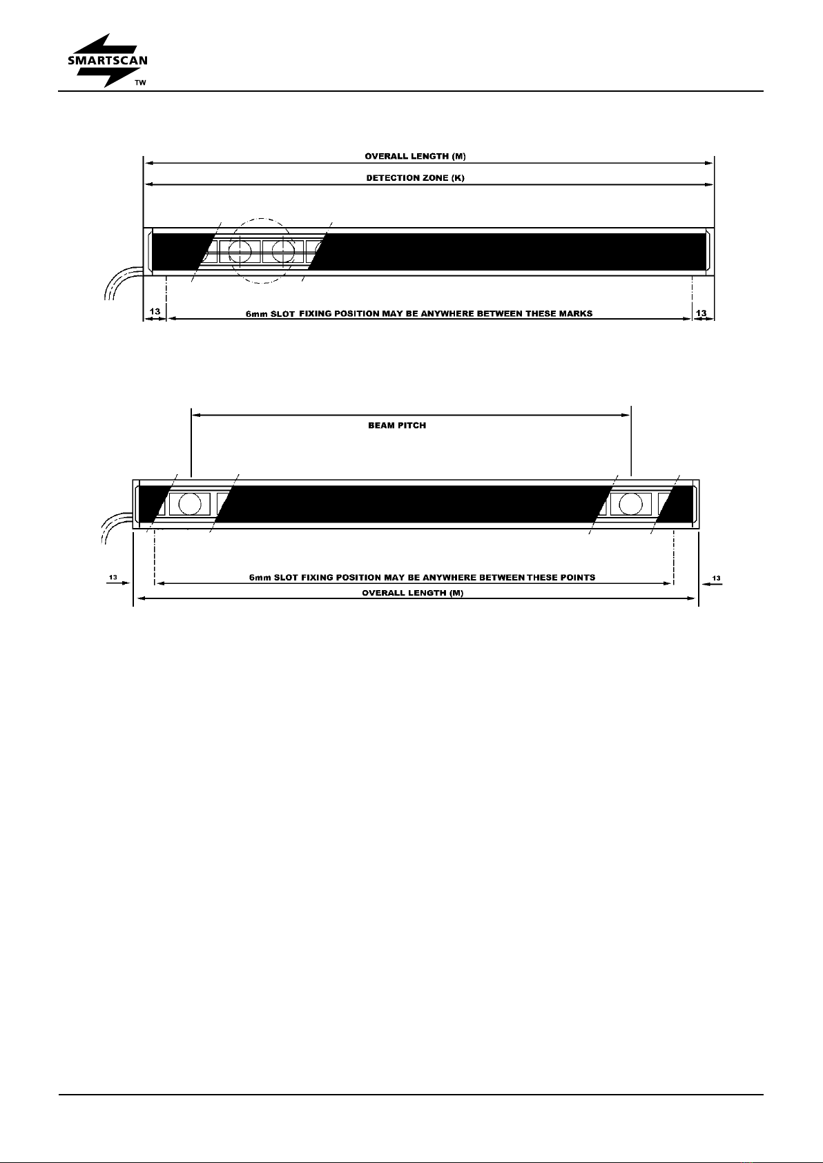
Figure C –Typical Mounting Arrangement for a Smartscan 1000
Plus
The 1000 Plus Series system does not use cable
connectors (only on direct wire-link model). Both
the transmitter and receiver units come complete
with 5m cables attached. Transmitter = 2 way
cable, Receiver = 4 way cable.
The 1000 Plus Series has a unique mounting
arrangement. Threaded slots running from top to
bottom of the transmitter and receiver columns
enable M6 screws to be affixed at any position
along the length of the slot.
The M6 threaded slots run the entire length of the
aluminum extrusion, between the two end caps.
There is a slot at each side of the extrusion and two
slots at the rear as shown in Figure C.
Note:
As an additional option a Mounting Bracket Kit
(012-130) is available.
Safety Light Curtain –1000+ Series
Installation Guide
File Number: CD1009A, CD1009B
page 9 Date: 10 October, 2016
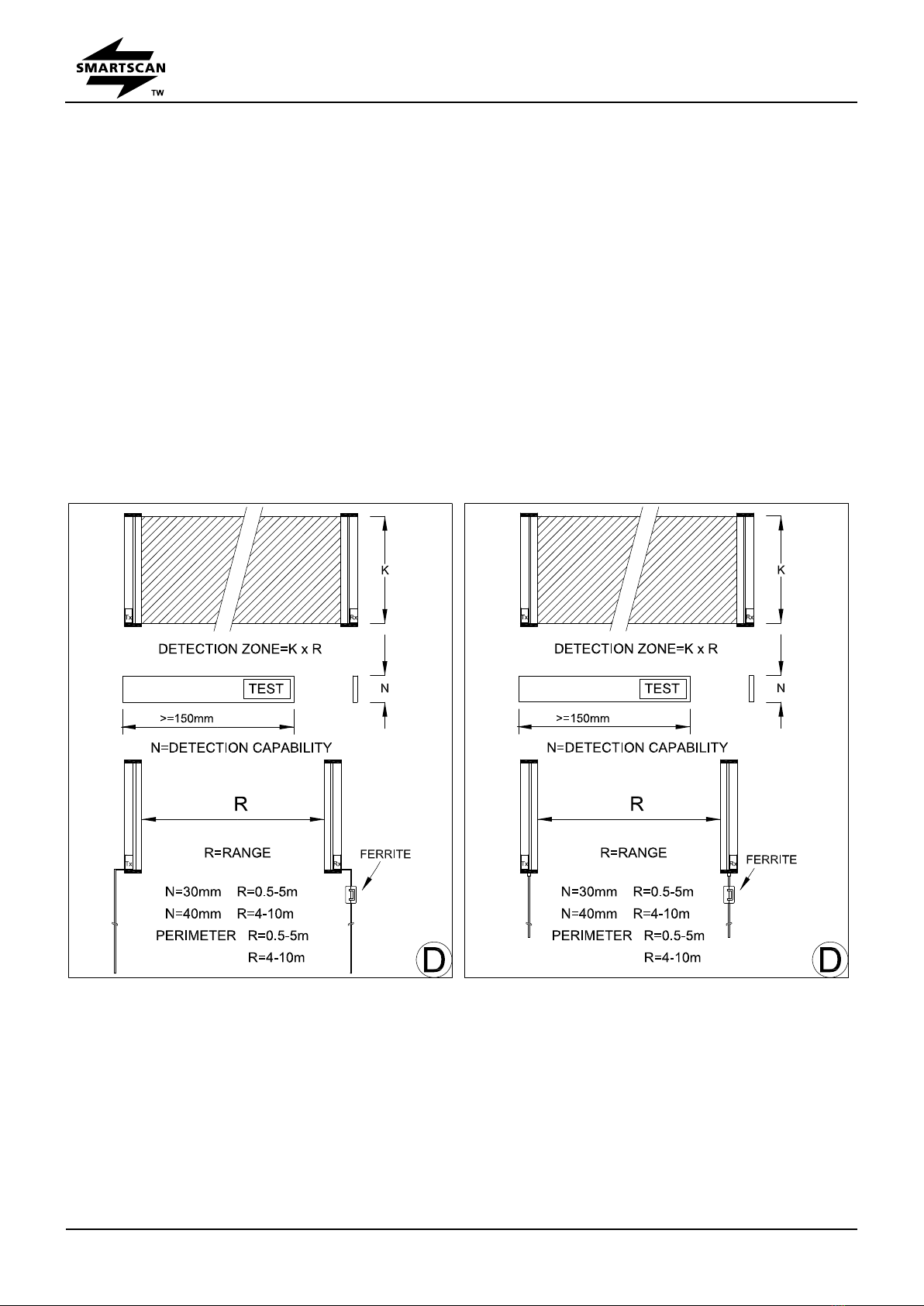
Figure D –Shows detection zone width, detection capability and
range options
Detection zone width (K) - Must be of a suitable height for each application to prevent
personnel access to the danger area either over, under or around the light curtains detection
zone.
Detection capability (N) - A test piece of appropriate size is provided to test that the light curtain
object detection capability is within the parameter specified for the particular model number.
Range (R) - Ensure the light curtain is capable of satisfying the range requirement for the
application.
CD1009A CD1009B

Safety Light Curtain –1000+ Series
Installation Guide
File Number: CD1009A, CD1009B
page 10 Date: 10 October, 2016
Figure E –Important Installation Considerations
When installing a Smartscan 1000 Plus Series light curtain your attention is drawn to the
following (Figure E):
1. Consider reflective surfaces that may give rise to optically ‘short circuiting’ the direct path of
the light curtains as shown in Figure E. To ensure the light curtain is mounted far enough
away from reflective surfaces use the formulae provided to calculate the minimum dimension
between the light curtain and reflective surface.
X = minimum distance between reflective surface and light curtain.
2. To prevent intermittent tripping of the light curtain
ensure extraneous infra red energy between 800
and 1000 nanometers is not directed towards the
Perspex window of the receiver unit (RX).
Extraneous sources would include infra red
sensors, infra-red remote controls or scanning
systems.
3. Ensure the mounting position of the light curtain in
respect to the nearest danger point meets the
requirements of European Standard ISO 13855.
4. Ensure the light curtain transmitter and receiver
units are mounted accurately in line with each other
and are both perpendicular and parallel to each
other within the parameters shown for each axis.
5. If utilising mirrors to deflect the light curtain ensure
the mirror length is 100mm longer than the light
curtain detection zone width and, mounted centrally
to the zone. To ensure reliable operation the light
curtain deflection angle from the mirror must not be
less than 40 degrees or greater than 100 degrees.

Safety Light Curtain –1000+ Series
Installation Guide
File Number: CD1009A, CD1009B
page 11 Date: 10 October, 2016
Figure F - Identification Labels
Figure F shows examples of the identification labels that are affixed to the end cap at the bottom
of the transmitter and receiver columns.
CD1009A CD1009B
Safety Light Curtain –1000+ Series
Installation Guide
File Number: CD1009A, CD1009B
page 12 Date: 10 October, 2016
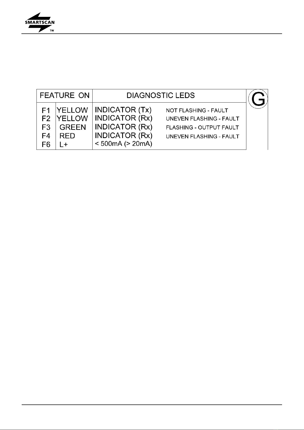
Figure G - Status and Diagnostic Indication
Figure G defines the features (F) associated with the Smartscan 1000 Plus system.
LED Status Indicators
F1 –If the yellow ‘flashing’ indicators on the (TX) transmitter column are flashing at an even flash
rate the unit is powered-up and the electronic system is operating normally.
F2 - Yellow ‘even-flashing’ indicators on the (RX) receiver column indicate that communication is
established between transmitter and receiver and the light curtain is correctly aligned. Yellow
‘steady’ indicators on the (RX) receiver column indicate that the light curtain is incorrectly aligned
or the light curtain detection zone is ‘blocked’.
F3 - Green LED indicator at the receiver unit illuminates when the electronic output switches,
OSSD1 and OSSD2 are ‘ON’ (only when the light curtain detection zone is ‘clear’ of any
obstruction).
F4 - Red LED indicator at the RX unit illuminates when the electronic output switches, OSSD1
and OSSD2 are ‘OFF’ e.g. a trip condition or, when the light curtain detection zone is ‘blocked’.
If the Red LED indicator is flashing the system is in lockout. To recover from a lockout condition
disconnect the transmitter and receiver from the power source and then re-apply.
F6 - Output Signal Switching Devices OSSD1 and OSSD2 provide the fail-safe signals for
switching a safe control relay or electrical contactor. Both output signals are termed, ‘control
reliable’; the transistor output switches are automatically turned ‘OFF’ for a very brief period of
time to enable the electronic safety system to automatically self-check thus ensuring the
switches are able to turn OFF permanently if required to do so. This function increases the
safety integrity of the Smartscan 1000 Plus system to a very high level. The switching period is
so short (500 .s max.) that it has no effect on the output signal to the machine safety circuits, thus

Safety Light Curtain –1000+ Series
Installation Guide
File Number: CD1009A, CD1009B
page 13 Date: 10 October, 2016
the machine will continue to operate during the automatic test periods.
Note: The standing current for each OSSD should be no less than 20mA
and no greater than 500 mA.
Safety Light Curtain –1000+ Series
Installation Guide
File Number: CD1009A, CD1009B
page 14 Date: 10 October, 2016
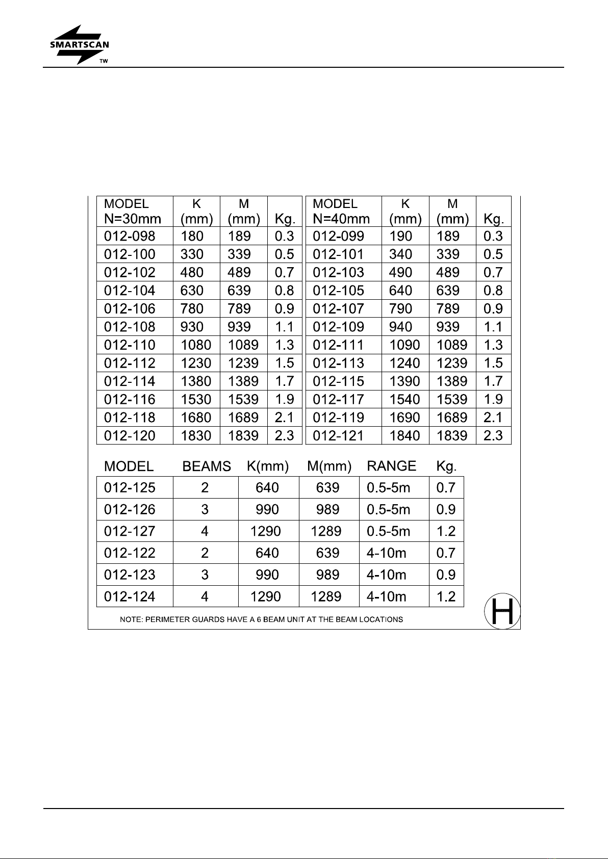
Figure H –Model List
Figure H shows the 1000 Plus Light Curtain model list showing part codes, detection zone width
(K) and combined weight in Kg of transmitter and receiver columns.
CD1009A

Safety Light Curtain –1000+ Series
Installation Guide
File Number: CD1009A, CD1009B
page 15 Date: 10 October, 2016
CD1009B
Light Curtains 30mm Detection Capability Range 0.5m to 5m
Safety Light Curtain –1000+ Series
Installation Guide
File Number: CD1009A, CD1009B
page 16 Date: 10 October, 2016
Light Curtains 40mm Detection Capability Range 4m to 10m
Light Curtains Perimeter Guarding Range 0.5m to 5m / Range 4m to 10m

Safety Light Curtain –1000+ Series
Installation Guide
File Number: CD1009A, CD1009B
page 17 Date: 10 October, 2016
Figure J –Electrical Connections
Input and Output Connections at the Transmitter and Receiver Units (Figure J)
A 24V DC regulated power supply should be
used for connection to the transmitter and
receiver units. The transmitter and
receiver units operate entirely independently
from each other, e.g. there are no electrical
connections between the transmitter and
receiver units therefore separate 24V DC
power supplies may be used if required. In
order to protect the 1000 Plus Series
electronic system please remember to
install fuses of suitable rating between
incoming 24V DC supply and 24V input
connections at both the transmitter and
receiver units. Recommended fuse ratings,
transmitter 0.5A and receiver 1.5A.
OSSD1 and OSSD2 - Each output switch has a maximum current rating of 0.5A. To prevent
possible damage never exceed the maximum current rating for the switching devices.
Ensure both transmitter and receiver units are connected to GROUND. Insert an M6 bolt into
one of the threaded slots in the extrusion to ensure a good ground connection.
Note: Inductive load suppressors should be used when driving large power
relays.

Safety Light Curtain –1000+ Series
Installation Guide
File Number: CD1009A, CD1009B
page 18 Date: 10 October, 2016
Glossary of Words and Language Translation
GLOSSARY of words and terminology used in the Installation Sheet in a number of International
languages:
Safety Light Curtain –1000+ Series
Installation Guide
File Number: CD1009A, CD1009B
page 19 Date: 10 October, 2016
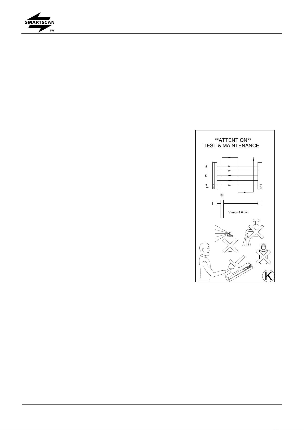
Figure K –Test and Maintenance
Testing the Light Curtain with the test piece
The test procedure should be carried out frequently as indicated by the risk assessment for the
particular installation. Smartscan Ltd recommends the test should be carried out daily.
Light curtains with ODC (N) 30mm / 40mm - refer to Figure K.
Power-up the light curtain and activate the output
switching circuits to an ON condition.
Insert a test piece of appropriate size into the light curtain
detection zone, at the bottom, 150mm from the
transmitter unit. At this point the output switches will turn
OFF. Sweep the test piece up through the detection
zone parallel to the transmitter. Now sweep the test
piece down through the detection zone equal distance
between the transmitter and receiver. Now sweep the
test piece up through the detection zone 150mm and
parallel to the receiver unit. At no time during these tests
should the output switches turn ON.
Now thrust the test piece anywhere in the light curtain
detection zone and ensure the machinery stops without
apparent delay.
For light curtain models with an ODC above 40mm / 55mm / 65mm undertake the same tests as
described. During these tests the output switches should only turn OFF as the test piece totally
obscures each beam in the light curtain. Ensure that while the test piece is obscuring each
beam the output switches are OFF.
The Transmitter (Tx) and Receiver (Rx) windows should be cleaned regularly as indicated on the
Installation Sheet.
No routine maintenance is required beyond periodic cleaning of the transmitter and receiver
windows. Dirt build up on the windows may lead to intermittent tripping or a totally blocked
condition of the light curtain. Clear adhesive tape may be applied to the windows of curtains in

Safety Light Curtain –1000+ Series
Installation Guide
File Number: CD1009A, CD1009B
page 20 Date: 10 October, 2016
dirty or abrasive conditions. Renew the clear adhesive tape periodically.
Clean the windows with a clean damp cloth using a mild detergent. Never use abrasive,
corrosive cleaners or spray detergents.
This manual suits for next models
2
Table of contents
Other SMART-SCAN Safety Equipment manuals


Popular Safety Equipment manuals by other brands

Klein Tools
Klein Tools CN1972ARL Instructions for Proper Use, Assembly and Care

Advance acoustic
Advance acoustic STRAPLESS 3 Getting started manual

Petzl
Petzl REEVE manual

Siemens
Siemens FS-MSM Installation and wiring instructions

Gemtor
Gemtor DAS-5K Operation and instruction manual

NOVOLEX
NOVOLEX FSP1713 manual

Datalogic
Datalogic SAFEasy SE4-PLUS Series instruction manual

GWP
GWP A60160 instruction manual

Petzl
Petzl QUICKFIX C09100 manual

bolle SAFETY
bolle SAFETY OMF164 quick start guide

SKYLOTEC
SKYLOTEC Climbing Technology BE UP manual

Soundoff Signal
Soundoff Signal PREDATOR EPRDDGS1 Series Assembly instructions


