GWP A60160 User manual

Product Name: Cable Horizontal Lifeline System
Part #: A60160 (60'), A100160 (100')
Instruction Manual
Do not throw away these instructions!
Read and understand these instructions before using equipment!
1
1
1
10-11
2
2-4
5-6
9
9
6-9
10
Introduction
Applicable Safety Standards
Worker Classifications
Product Specific Applications
Limitations
Components and Specifications
Installation and Use
Maintenance, Cleaning, and Storage
Inspection
Inspection Log
Safety Information

Introduction
Thank you for purchasing a Palmer Safety
Fall Protection Cable Horizontal Lifeline
System (Cable HLL System). This manual
must be read and understood in its
entirety, and used as part of an employee
training program as required by OSHA or
any applicable state agency.
This and any other included instructions
must be made available to the user of the
equipment. The user must understand how
to safely and effectively use the Cable HLL
System, and all fall safety equipment used
in combination with the Cable HLL System.
User Information
Date of First Use:
Serial #:
Trainer:
User:
Applicable Safety Standards
When used according to instruction specifications, this product meets or exceeds all applicable OSHA 1926
Subpart M, OSHA 1910, ANSI Z359.6-2016, and ANSI A10.32-2012 standards for fall protection. Applicable
standards and regulations depend on the type of work being done, and also might include state-specific
regulations. Consult regulatory agencies for more information on fall protection systems and associated
components.
Worker Classifications
!
CAUTION
Understand the following definitions of those who
work near or who may be exposed to fall hazards.
Qualified Person: A person with an accredited degree or certification, and with extensive experience or
sufficient professional standing, who is considered proficient in planning and reviewing the conformity of fall
protection and rescue systems.
Competent Person: A highly trained and experienced person who is ASSIGNED BY THE EMPLOYER to be
responsible for all elements of a fall safety program, including, but not limited to, its regulation, management,
and application. A person who is proficient in identifying existing and predictable fall hazards, and who has
the authority to stop work in order to eliminate hazards.
Authorized Person: A person who is assigned by their employer to work around or be subject to potential or
existing fall hazards.
It is the responsibility of a Qualified or Competent person to supervise the job site and ensure all
applicable safety regulations are complied with.
1
Palmer Safety Fall Protection 6000 Jefferson Highway Harahan, LA 70123 phone: (504) 733-1808 email: [email protected] palmersafetyus.com

2
Product Specific Applications
Personal Fall Arrest: The Cable HLL System may be used in Personal Fall Arrest (PFAS)
applications. Maximum 2 users per Cable HLL System when working in Fall Arrest. Structure must
withstand loads applied in the directions permitted by the system of at least 5,000 lbs. per PFAS
in system. Maximum free fall is 6’, or up to 12’ if used in combination with equipment explicitly
certified for such use. Applicable D-ring: Dorsal.
Restraint: The Cable HLL System may be used in Restraint applications. Restraint systems prevent
workers from reaching the leading edge of a fall hazard. Maximum 4 users per Cable HLL System
when working in Restraint. Always account for fully deployed length of lanyard/SRL. Structure
must withstand loads applied in the directions permitted by the system of at least 1,000 lbs. No
free fall is permitted. Restraint systems may only be used on surfaces with slopes up to 4/12
(vertical/horizontal). Applicable D-rings: Dorsal, Chest, Side, Shoulder.
!
WARNING
Use of equipment in unintended applications may result in serious
injury or death. Maximum 1 attachment per connection point.
For all applications: worker weight capacity range
(including all clothing, tools, and equipment) is 130-420 lbs.
Limitations
Fall Clearance: There must be sufficient clearance below the anchorage connector to arrest a fall before
the user strikes the ground or an obstruction. When calculating fall clearance, account for a MINIMUM 2’
safety factor, deceleration distance, user height, length of lanyard/SRL, harness stretch, lifeline deflection,
and all other applicable factors.
Diagram shown is an example fall clearance calculation ONLY.
TOTAL FALL CLEARANCE = DEFLECTION + FREE FALL + DECELERATION + STRETCH + Safety MARGIN + Swing Fall
Work Surface
Anchor Point Cable HLL System with 6” Sag
Deceleration Distance
Lifeline Deection
Harness Stretch (1.5’)
Safety Margin (2’)
Free Fall Distance
Work Surface
Swing Fall (If Applicable)
DEFLECTION What’s the length of your HLL span?
39.05”
SPAN =
DEFLECTION = 94.83”
10’
52.01”
20’
62.18”
30’
71.00”
40’
86.99”
60’
79.14”
50’ 70’
102.89”
80’
111.35”
90’
120.38”
100’
Anchor Point
Clearance data determined based on HLL level with harness dorsal D-ring (from a standing working position).
Always account for additional free fall if HLL is below dorsal D-ring.
Palmer Safety Fall Protection 6000 Jefferson Highway Harahan, LA 70123 phone: (504) 733-1808 email: [email protected] palmersafetyus.com

Ø: Total Working Angle
X: Working Distance
Along Leading Edge
Y: Distance From
Leading Edge
X
Y
ø
X
Leading Edge
3
Compatibility: When making connections with Cable HLL System, eliminate all possibility of roll-out. Roll-out
occurs when interference between a hook and the attachment point causes the hook gate to unintentionally
open and release. All connections must be selected and deemed compatible with Cable HLL System by a
Competent Person. All connector gates must be self-closing and self-locking, and withstand minimum loads of
3,600 lbs. See the following for examples of compatible/incompatible connections:
Correct Anchorage Positioning:
This chart details allowable working zones required
to reduce risk of swing falls and improper side loading.
ALWAYS adhere to information specified by chart.
Anchor Distance
From
Leading Edge (Y)
Working Distance
Along Roof Edge
(Either Direction) (X)
Working Angle
From
Perpendicular (Ø)
6’
10’
15’
20’
25’
30’
35’
40’
45’
50’
55’
60’
8’
9’ - 9”
11’ - 7”
13’ - 3”
14’ - 6”
16’
17’ - 2”
18’ - 3”
19’ - 4”
19’ - 10”
21’ - 4”
22’ - 3”
53°
45°
38°
33°
30°
28°
26°
24°
23°
21°
21°
21°
For example, if the anchorage connector is 6’ from the leading
edge (Y), the working distance (X) is 8’ in each direction from
the perpendicular, which translates to a 53° working angle.
Swing Falls: Prior to installation or use, make considerations for eliminating or minimizing all swing fall
hazards. Swing falls occur when the anchor is not directly above the location where a fall occurs. Always work
as close to in line with the anchor point as possible. Swing falls significantly increase the likelihood of serious
injury or death in the event of a fall.
As shown in following image, there are potential danger zones for swing falls when using a single HLL span.
Use multiple HLL spans to expand area of coverage.
Connector
closed and
locked to
D-ring. OK.
Connector
to integral
lanyard.
NO.
Two or
more snap
hooks or
carabiners
connected
to each
other. NO.
Two connectors
to same
D-ring. NO.
Connector
directly to
webbing.
NO.
Incompatible
or irregular
application,
which may
increase risk
of roll-out. NO.
Palmer Safety Fall Protection 6000 Jefferson Highway Harahan, LA 70123 phone: (504) 733-1808 email: [email protected] palmersafetyus.com

4
SAFE ATTACHMENT ZONE
DANGER ZONE:
WORK IN THIS
AREA NOT ALLOWED
Horizontal Lifeline
100’
120’
60’
SAFE ATTACHMENT ZONE
EXTENDS FOR ENTIRE
BUILDING ROOF PERIMETER
Horizontal Lifeline
120’
PLACE HLL 6’-10’ BACK
FROM LEADING EDGE
60’
Palmer Safety Fall Protection 6000 Jefferson Highway Harahan, LA 70123 phone: (504) 733-1808 email: [email protected] palmersafetyus.com

5
Components and Specifications
Components made from some or all of the following: galvanized steel and stainless steel.
Palmer Safety Fall Protection 6000 Jefferson Highway Harahan, LA 70123 phone: (504) 733-1808 email: [email protected] palmersafetyus.com

Palmer Safety Fall Protection 6000 Jefferson Highway Harahan, LA 70123 phone: (504) 733-1808 email: [email protected] palmersafetyus.com
6
Prior to installation, plan your system:
1. Ensure selected installation location(s) for Cable HLL System (s) will withstand minimum loads as specified
by this instruction manual.
2. ALWAYS make considerations to eliminate or reduce swing fall hazards.
3. Fall clearance for each installation location MUST be calculated by a Competent Person, and MUST be
considered in the selection of PFAS equipment.
4. Ensure all components of PFAS are selected and deemed compatible with Cable HLL System by a
Competent Person.
5. Ensure entire Cable HLL System design and installation is done under supervision of Competent Person.
NEVER judge Cable HLL tension by eye; ALWAYS measure line sag and keep in concordance with sag
requirements specified by this instruction manual. NEVER over-tighten cable. Proper sag in cable reduces
forces of Fall Arrest.
6. If performing installation at heights over 6’, ALWAYS use a complete and independent PFAS until Cable HLL
System is fully installed and able to withstand forces of Fall Arrest as specified by this instruction manual.
Always maintain 100% tie-off.
Palmer Safety recommends using 3/8” diameter cable. DO NOT use vinyl/plastic coated cable.
MINIMUM 1 Absorber required for systems up to 60’. MINIMUM 2 Absorbers required for systems longer than
60’. Entire Cable HLL System MUST NOT span more than 100’.
Installation and Use
Installation:
Tools needed for installation:
• 5/16” (8mm) wrench, 3/4” (19mm) wrench, 19/32” (15mm) wrench, Adjustable wrench, Torque wrench
(capable of measuring foot-pounds).
1. Select locations for all anchor points in Cable HLL System. Ensure anchor points meet stated strength
requirements. Ensure proper fall clearance exists for entire system.
2. Lay out as much of Cable HLL System as possible prior to attaching it to anchorage connectors.

Palmer Safety Fall Protection 6000 Jefferson Highway Harahan, LA 70123 phone: (504) 733-1808 email: [email protected] palmersafetyus.com
7
CLOSED EXTENDED
8. Install O-rings on HLL cable. Then, take one end of 3/8” cable and create a loop around the thimble. See
Appendix A (pgs. 8-9) for fist grip installation instructions. Repeat on opposite end of system.
9. Tighten turnbuckle evenly on both ends so there is between 2” - 6” of slack measured vertically at
midpoint of span. Qualified Person must make final determination regarding sufficient cable slack.
6. Attach one end of turnbuckle to Absorber at one end of
system, and tighten until at least 1 full thread is visible.
7. Place wire rope thimble on other end of turnbuckle. Tighten bolt until at least 1 full thread is visible.
Attach second steel shackle and thimble to anchor point or Absorber at opposite end of system (second
turnbuckle is not used).
Slack: 2” - 6”
Tightening bolts on the Cable HLL System
YES NO
3. Attach Cable HLL System to anchor point using provided steel
shackle. If system is more than 60’, attach second Absorber to
anchor point at other end of system. Tighten shackle until at least 1
full thread is visible.
4. Make any other necessary attachments to anchorage connectors.
*In the event that a 90° corner is needed, two Cable HLL Systems
may be attached to a single anchor point as shown.
5. Adjust turnbuckle(s) to extended position (see below).

Appendix A:
Fist Grip: compatible with cable diameters from 3/16” - 5/8”.
Efficiency ratings for wire rope end terminations are based upon the catalog breaking
strength of wire rope. The efficiency rating of a properly prepared loop or thimble-eye
termination for clip sizes 1/8” through 7/8” is 80%, and for 1” through 3½” is 90%.
!
WARNING
Prepare wire rope end termination only as instructed.
DO NOT use vinyl/plastic coated wire rope.
Apply first load to test the assembly. This load should be of
equal or greater weight than loads expected in use.
The number of clips shown (see Table 1) is based upon using RRL or RLL wire rope, 6 x 19 or 6 x 37 Class FC or
IWRC, IPS or XIP, or XXIP. If Seale construction or similar large outer wire type construction in the 6 x 19 Class is
to be used for sizes 1” or larger, add one additional clip. If a pulley (sheave) is used for turning back the wire
rope, add one additional clip.
The number of clips shown also applies to rotation-resistant RRL wire rope, 8 x 19 Class IPS, XIP, or XXIP sizes
1½” and smaller; and to rotation-resistant RRL wire rope, 19 x 7 Class IPS, XIP, or XXIP sizes 1½” and
smaller. For other classes of wire rope not mentioned above, we recommend contacting Crosby Engineering to
ensure the desired efficiency rating. The style of wire rope termination used for any application is the
obligation of the user.
1. Refer to Table 1 in following these instructions. Turn back specified amount of rope from thimble or loop.
Apply first clip one base width from dead end of rope. Use torque wrench to evenly tighten clip, alternating
from one nut to the other until reaching the recommended torque.
FIGURE 1
FIGURE 2
3. When three or more clips are used, space additional clips equally between first two. Take up rope slack,
use torque wrench to tighten on each clip evenly, alternating from one nut to the other until reaching
recommended torque.
FIGURE 3
Live End
Dead End
Palmer Safety Fall Protection 6000 Jefferson Highway Harahan, LA 70123 phone: (504) 733-1808 email: [email protected] palmersafetyus.com
8
2. When two clips are required, apply the second clip as near the loop or thimble as possible. Use torque
wrench to evenly tighten clip, alternating until reaching the recommended torque. When more than two clips
are required, apply the second clip as near the loop or thimble as possible, turn nuts on second clip firmly, but
do not tighten.

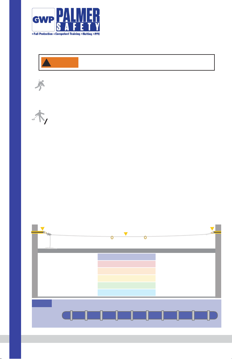
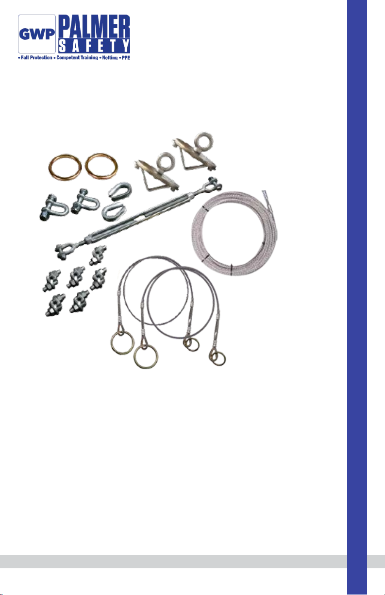
4. O-rings and sliders: Palmer Safety
provides (2) 2½” O-rings that should be
applied to the cable lifeline to allow
compatible attachment of snap hooks and
other connecting devices.
O-rings and sliders must be attached to the
lifeline before the system is complete.
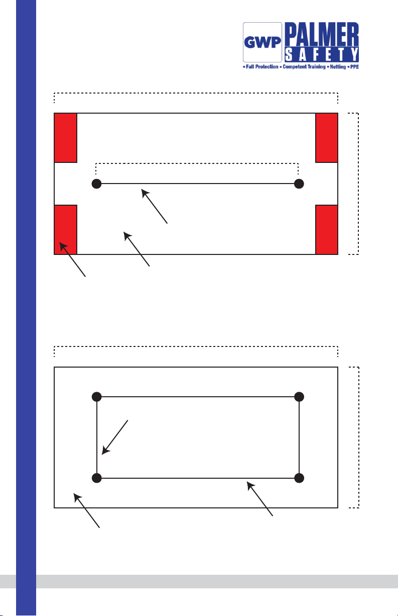
For systems with multiple intermediate
anchor points or for any other questions,
contact Palmer Safety Fall Protection .
Table 1
Clip Size
(in.)
Rope Size
(in.)
Minimum
# of Clips
Amount of
Rope to Turn
Back (in.)
Torque
(ft. lbs.)
3/16
1/4
5/16
3/8
7/16
1/2
9/16
5/8
3/4
7/8
1
11/8
1¼
13/8
1½
3/16
1/4
5/16
3/8
7/16
1/2
9/16
5/8
3/4
7/8
1
11/8
1¼
13/8
1½
2
2
2
2
2
3
3
3
3
4
5
5
6
6
7
4
4
5
5¼
6½
11
12¾
13½
16
26
37
41
55
62
78
30
30
30
45
65
65
130
130
225
225
225
360
360
500
500
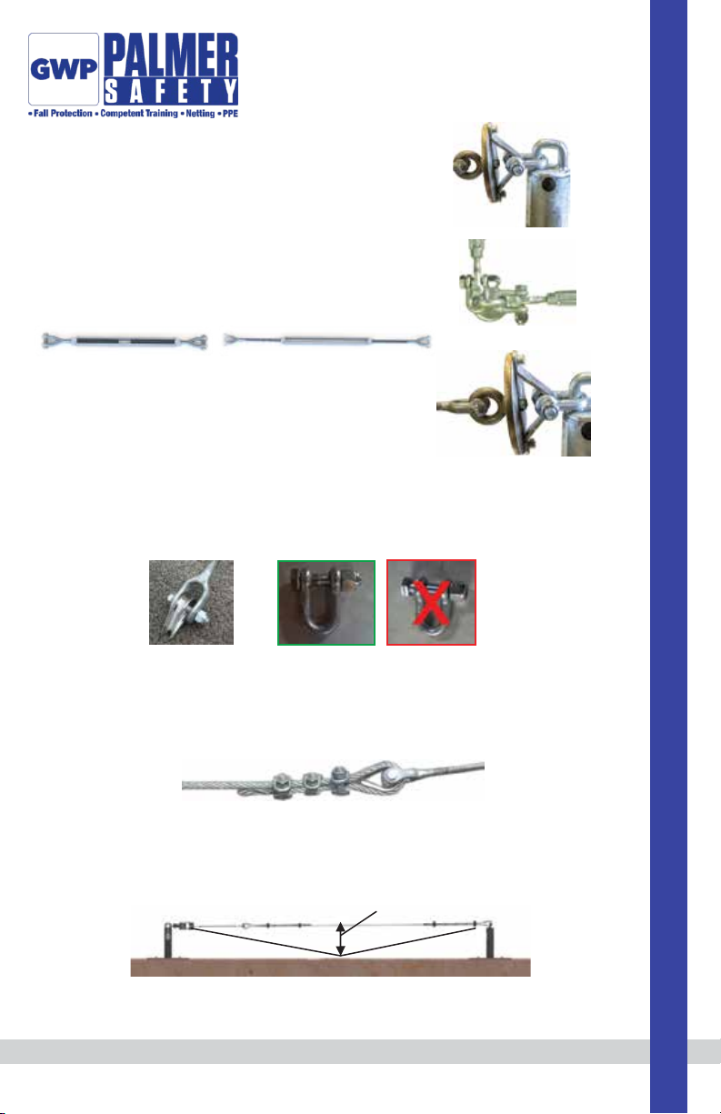
If greater number of clips than shown are used, amount of turn-back should be increased proportionately.
Torque values shown are based upon the threads being clean, dry, and free of lubrication.
Palmer Safety Fall Protection 6000 Jefferson Highway Harahan, LA 70123 phone: (504) 733-1808 email: [email protected] palmersafetyus.com
9
Maintenance, Cleaning, and Storage
If Cable HLL System fails inspection in any way, immediately remove it from service, and contact Palmer
Safety to inquire about its return or repair.
Cleaning after use is important for maintaining the safety and longevity of Cable HLL System. Remove all
dirt, corrosives, and contaminants from Cable HLL System before and after each use. If Cable HLL System
cannot be cleaned with plain water, use mild soap and water, then rinse and wipe dry. NEVER clean Cable
HLL System with corrosive substances.
When not in use, store equipment where it will not be affected by heat, light, excessive moisture,
chemicals, or other degrading elements.
Inspection
Prior to EACH use, inspect Cable HLL System for deficiencies, including, but not limited to, corrosion,
deformation, pits, burrs, rough surfaces, sharp edges, cracking, rust, paint buildup, excessive heating,
alteration, fraying, bird-caging, and missing or illegible labels. IMMEDIATELY remove Cable HLL System from
service if defects or damage are found, or if exposed to forces of Fall Arrest.
Ensure that applicable work area is free of all damage, including, but not limited to, debris, rot, rust, decay,
cracking, and hazardous materials. Ensure that selected work area will support the application-specific
minimum loads set forth in this instruction manual. Work area MUST be stable.
At least every 6 months, a Competent Person other than the user must inspect Cable HLL System.
Competent Person inspections MUST be recorded in inspection log in instruction manual and on equipment
inspection grid label. The Competent Person must sign their initials in the box corresponding to the month
and year the inspection took place.
During inspection, consider all applications and hazards Cable HLL System has been subjected to.

Palmer Safety Fall Protection 6000 Jefferson Highway Harahan, LA 70123 phone: (504) 733-1808 email: [email protected] palmersafetyus.com
10
Safety Information
Failure to understand and comply with safety regulations may result in
serious injury or death. Regulations included herein are not all-inclusive,
are for reference only, and are not intended to replace a Competent
Person’s judgment or knowledge of federal or state standards.
!
WARNING
If equipment fails inspection IMMEDIATELY REMOVE FROM SERVICE.
Inspection Log
Date of First Use: __________________.
Product lifetime is indefinite as long as it passes pre-use and Competent Person inspections. User must
inspect prior to EACH use. Competent Person other than user must complete formal inspection at least
every 6 months. Competent Person to inspect and initial.
This inspection log must be specific to one Cable HLL System. All inspection records must be made
visible and available to all users at all times.
Do not alter equipment. Do not misuse equipment.
Workplace conditions, including, but not limited to, flame, corrosive chemicals, electrical shock, sharp objects,
machinery, abrasive substances, weather conditions, and uneven surfaces, must be assessed by a Competent
Person before fall protection equipment is selected.
The analysis of the workplace must anticipate where workers will be performing their duties, the routes they
will take to reach their work, and the potential and existing fall hazards they may be exposed to. Fall
protection equipment must be chosen by a Competent Person. Selections must account for all potential
hazardous workplace conditions. All fall protection equipment should be purchased new and in an unused
condition.
Fall protection systems must be selected and installed under the supervision of a Competent Person, and used
in a compliant manner. Fall protection systems must be designed in a manner compliant with all federal, state,
and safety regulations. Forces applied to anchors must be calculated by a Competent Person.
Unless explicitly stated otherwise, the maximum allowable free fall distance for lanyards must not exceed 6’.
No free fall allowed for non-LE SRLs. Class A SRLs must arrest falls within 24”; Class B SRLs must arrest falls
within 54”.

Palmer Safety Fall Protection 6000 Jefferson Highway Harahan, LA 70123 phone: (504) 733-1808 email: [email protected] palmersafetyus.com
11
Harnesses and connectors selected must be compliant with manufacturer’s instructions, and must be of
compatible size and configuration. Snap hooks, carabiners, and other connectors must be selected and applied
in a compatible fashion. All risk of disengagement must be eliminated. All snap hooks and carabiners must be
self-locking and self-closing, and must never be connected to each other.
A pre-planned rescue procedure in the case of a fall is required. The rescue plan must be project-specific. The
rescue plan must allow for employees to rescue themselves, or provide an alternative means for their prompt
rescue. Store rescue equipment in an easily accessible and clearly marked area.
Training of Authorized Persons to correctly erect, disassemble, inspect, maintain, store, and use equipment
must be provided by a Competent Person. Training must include the ability to recognize fall hazards, minimize
the likelihood of fall hazards, and the correct use of personal fall arrest systems.
NEVER use fall protection equipment of any kind to hang, lift, support, or hoist tools or equipment, unless
explicitly certified for such use.
Equipment subjected to forces of fall arrest must immediately be removed from use.
Age, fitness, and health conditions can seriously affect the worker should a fall occur. Consult a doctor if there
is any reason to doubt a user’s ability to withstand and safely absorb fall arrest forces or perform set-up of
equipment. Pregnant women and minors must not use this equipment.
Physical harm may still occur even if fall safety equipment functions correctly. Sustained post-fall suspension
may result in serious injury or death. Use trauma relief straps to reduce the effects of suspension trauma.
This manual suits for next models
1
Table of contents
Other GWP Safety Equipment manuals
Popular Safety Equipment manuals by other brands

Sperian
Sperian Miller FALCON Series General Instructions for Use

SKYLOTEC
SKYLOTEC SECUPIN SPA-TYP-1-L Instructions for use

Singing rock
Singing rock FOOTER II quick start guide

PRIMAL TREESTANDS
PRIMAL TREESTANDS PTDH-903W Instruction and safety manual

Petzl
Petzl METEOR III+ Instructions for use

Dräger
Dräger Saver PP Series quick start guide