Printed in USA
Safety Technology International
2306 Airport Road • Waterford, Michigan 48327-1209
Phone: 248-673-9898 • Toll Free: 800-888-4784
Fax: 248-673-1246 • www.sti-usa.com
Safety Technology International (Europe)
Taylor House • 34 Sherwood Road • Bromsgrove
Worcestershire • B60 3DR • England
Tel: +44 (0)1527 520 999 • Fax: +44 (0)1527 501 999
CIRCUIT BOARD SET-U
Inst. Sht. 7532, 7533, &7533AED, CT2018
WARNINGS
WARRANTY INFORMATION
S ECIFICATIONS
All units are recommended for indoor use. Unit must be tested periodically to verify the life of battery. STI recommends you change the battery twice a year. Duracell
MN 1604 or equivalent recommended. Installer may need to purchase a simple audio-meter, typically available at your local electronics store, to measure the sound
in areas where the alarm is expected to be heard during normal noise environment. Results from this test may prove it beneficial to purchase an additional alarm.
When purchasing a remote unit (STI-6403) you will need to periodically test the connections to make sure audibles function at a sound level to alert staff. Maximum of
three STI-6403 may be used in parallel. All specifications and information shown are current as of publication and subject to change without notice.
This product can expose you to chemicals including Bisphenol A, which is known to the State of California to cause reproductive harm and Dichloromethane,
which is known to the State of California to cause cancer. For more information go to www. 65Warnings.ca.gov.
Three year warranty or a one year limited warranty (from date of purchase) on most products. See website for details.
Electronic warranty form at www.sti-usa.com/wc14.
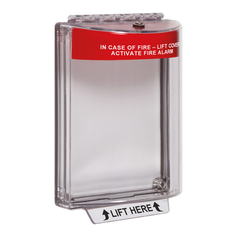
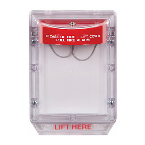
olycarbonate Alarm Cover
Dimensions 5.375” W x 5.375” H x 2 “ D
(137mm x 137mm x 51mm)
Flammability: UL94 V-2
Wall Thickness: 0.12 in (3.05mm)
Remote
Power
Form C
Relay
RS2RS1
JUMPER WIRE
Switch Settings
(defaults shown)
KEYSW
TO MAGNETIC SWITCH
All models are shipped with
jumper across RS2 terminals for
use with one reed switch. If using
second reed switch, remove
jumper wire and insert second
reed switch.
SWITCH SETTINGS 1 2 3 4 5 6 7 8
Arming - immediate OFF*
Arming - 15 second delay ON
Trip - immediate OFF*
Trip - 15 second delay ON
Shut-off based on duration
Shut-off approx. 3 sec. after
Duration - 30 second alarm OFF* OFF*
Duration - 180 second alarm OFF ON
Duration - continuous alarm ON OFF
Duration - annunciator mode ON ON
Low battery detection on - Turn switch off OFF*
Low battery detection off - Turn switch on ON
Volume - high ON*
Volume-low OFF
Relay function OFF OFF*
Relay function ON ON
OFF*
ON
door closes
(switches 4 & 5)
*default
9 VDC battery
If not using, slide switch 6 “on”
12VDC - 24VDC, 300mA
Installed battery will act as backup power if switch 6 is “off”
30 cm high volume 112dB; low volume 97dB
100 cm high volume 102dB; low volume 88dB
Flash 1x / minute; beep 1x / 3 minutes
0.5A 125VAC / 1A 30VDC
Battery <15µA (Battery Life approx. 2 years dependent on use)
12VDC <0.15mA
24VDC <1mA
<286mA @12VDC <149mA @24VDC
14°F to 122°F (-10°C to 50°C)
2 flashes and 2 beeps
1 flash and 1 beep
Power source
Remote power input
Low battery detection
Relay contacts
Stand by current
Alarm current (volume high + relay)
Operating temperature
Power “on” notification
Power “off” notification
Horn volume
E
Electronics
