SMART-SCAN 8K3 Series User manual

8K3 SERIES
CROSS-BEAM MUTING
ACCESSORIES
INSTALLATION GUIDE
MACHINERY SAFETY SYSTEMS

Smartscan Ltd
Pywell Road
Willowbrook Industrial Estate
Corby
Northamptonshire
NN17 5XJ - England
Tel. +44 (0)1536 –401 313
www.smartscan.co.uk
Important!
Failure to read and follow the instructions provided on the Installation Sheet
and Installation Guide can lead to the incorrect application or use of the 8K3
series mute accessories. This could lead to personal injury and damage to
equipment. The 8K3 series safety light curtain Installation Sheet and
Installation Guide must be used in conjunction with the 8K3 series mute
accessories Installation Sheet and Installation Guide. All applicable machine
safety standards and regulations should be taken into account when installing
the 8K3 series mute accessories or any machine safety product.
The Installation Sheet and Installation Guide can be downloaded from our web
site at www.smartscan.co.uk
The 8K3 series mute accessories Installation Guide (CD693) is subject to
change without notice. Smartscan Ltd shall not be held responsible for
technical errors, editorial errors or omissions contained herein, nor for
incidental or consequential damages resulting from the use of this material.
© 2019 Smartscan Ltd. All Rights Reserved. Unless explicitly stated
otherwise, all rights including those in copyright in the content of this document
are owned by or controlled for these purposes by Smartscan Ltd.
Except as otherwise expressly permitted under copyright law or Smartscan
Ltd, reproduction of the document or alteration of this document may not be
carried out in any way without first obtaining Smartscan Ltd's written
permission.

CONTENTS
FIGURE A - UNPACKING ..........................................................................................................1
FIGURE B –DIMENSIONAL INFORMATION ........................................................................... 2
FIGURE C –MUTING MODULE MECHANICAL CONNECTION..............................................3
FIGURE D –RETRO-REFLECTIVE PHOTOCELL CONNECTION .......................................... 4
FIGURE E –MUTE MODULES SHOWING MUTE BEAM ARRANGEMENTS ........................ 5
MUTE ENABLE INPUT.................................................................................................................6
FIGURE F –PALLET LOAD POSITIONING..............................................................................7
FIGURE G –OPERATING REQUIREMENTS ........................................................................... 8
ACTIVATE SWITCH ELECTRICAL CONNECTION ............................................................................9
FIGURE H –MUTING TIMER SEQUENCE .............................................................................10
CROSS-BEAM CONTROL TIMERS..............................................................................................10
FIGURE I –IDENTIFICATION LABELS ..................................................................................11
FIGURE J –TEST AND MAINTENANCE................................................................................12
TESTING THE MUTE ACCESSORIES WITH A TEST PIECE...............................................................12
MAINTENANCE ........................................................................................................................13
FIGURE K –OPERATION CYCLE...........................................................................................14
FIGURE L –PRODUCT RETURN PROCEDURE....................................................................15
FIGURE M –DECLARATION OF CONFORMITY ...................................................................16
FIGURE N –GLOSSARY OF WORDS AND LANGUAGE TRANSLATION...........................17
APPENDIX 1 –IMPORTANT SAFETY WARNING INFORMATION.......................................18
APPENDIX 2 - CERTIFICATIONS............................................................................................19
NOTES ......................................................................................................................................20
8K3 Series Cross-Beam Mute Accessories Installation Guide
CD693/150120 Smartscan Ltd
1
8K3 Series (Model No. 087-xxxxx) Mute Accessories
Installation Sheet (CD692/150120)
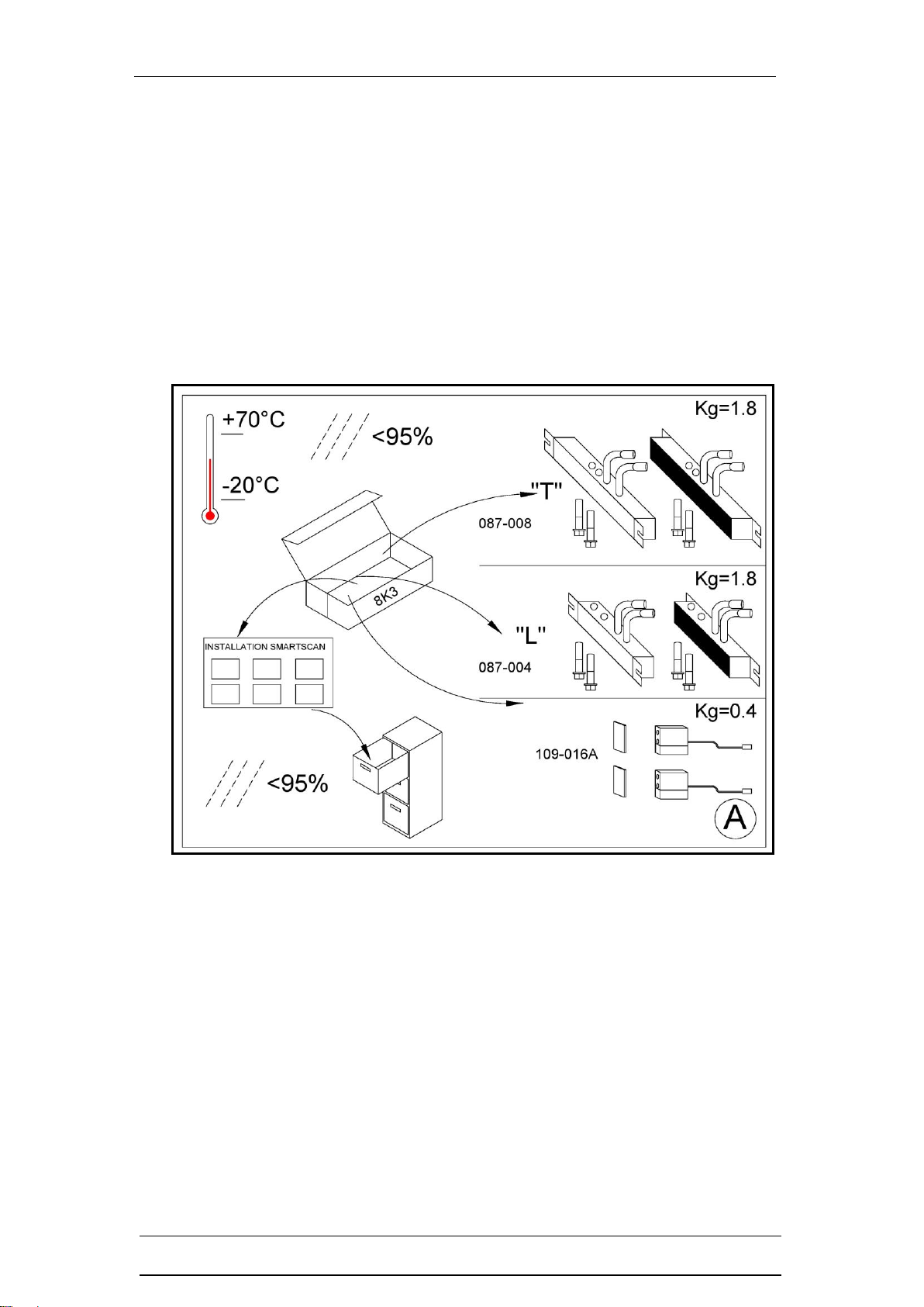
Figure A - Unpacking
❑Remove all packaging material and retain it
❑Locate and keep the delivery note
❑Inspect all items for transit damage
❑Match goods supplied to those specified on the delivery note
❑Keep the Installation Sheet in a safe place
Each 8K3 series mute accessory kit supplied would normally include:
❑Pair of ‘L’ or ‘T’ muting modules with fixing bolts or polarised retro-reflective
sensors with cables and connectors affixed, together with mounting brackets.
❑Installation sheet
❑Service questionnaire form
Storage requirements:
❑Humidity - <95%
❑Temperature range between –20°C and +70°C

8K3 Series Cross-Beam Mute Accessories Installation Guide
CD693/150120 Smartscan Ltd
2
Figure B –Dimensional Information
The 8K3 Series T and L cross-beam muting modules have the same cross section
as the light curtain, 50 x 50mm.
8K3 Series Cross-Beam Mute Accessories Installation Guide
CD693/150120 Smartscan Ltd
3
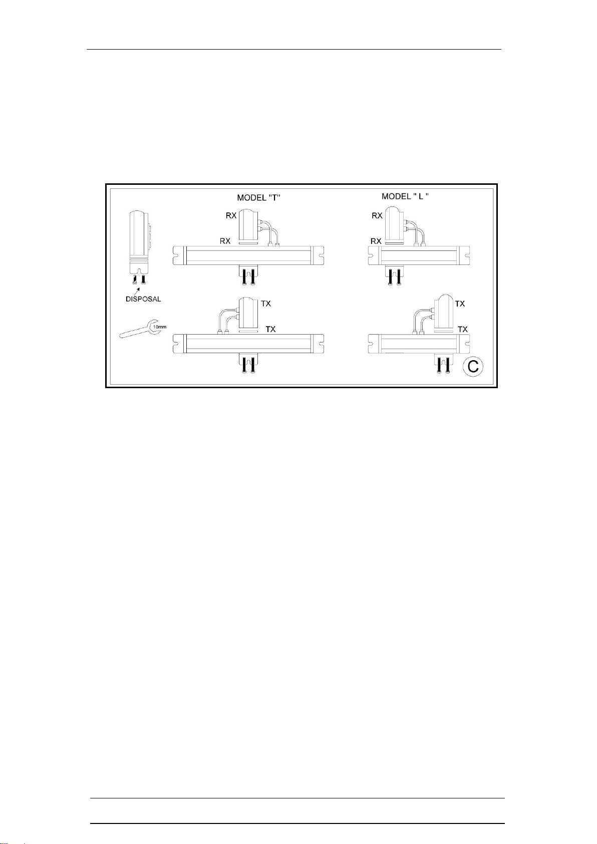
Figure C –Muting Module Mechanical Connection
Fixing ‘L’ or ‘T’ cross-beam mute modules to the safety light curtain columns is
very easy. Undo the fixing bolts and remove the end-cap fixing bracket and
rubber seal from both the transmitter (Tx) and receiver (Rx) columns.
Fit the appropriate ‘L’ or ‘T’ module to the base of each column using the longer
bolts that are supplied with the units. Tighten the bolts enough to ensure
waterproof sealing between the aluminium housings. If an additional guard
mounting point is required the bottom end cap bracket can be re-fitted underneath
the mute module housing.
Red LED’s in the receiver Rx mute module are illuminated to show the mute
beams are active.
On the Receiver (Rx) the two mute inputs are situated below the B (User) cable
connection and the A (interconnect) cable connection. On the Transmitter (Tx)
head the mute inputs are situated below the A (interconnect) cable connection.
Plug in the two cables from the Mute modules to the light curtain column as
shown above. Note the Rx Mute module cables must be crossed when using the
inverted ‘T’shape cross-beam muting or the ‘L’shape cross-beam muting. The
cables are connected so they are parallel when using the parallel beam muting
(timing control).

8K3 Series Cross-Beam Mute Accessories Installation Guide
CD693/150120 Smartscan Ltd
4
Figure D –Retro-Reflective Photocell Connection
The picture shows options for configuring the 8K3 series safety light curtain in
applications using non-integrated mute sensors.
There are particular applications where the standard mute modules are not
suitable for example, where there is a limitation in the space available for
mounting the modules. In such cases external sensors that allow more flexibility
are often used.
Polarised retro-reflective sensor - Type 109-016A, Maximum range = 4m
The sensor transceiver comes complete with polarised reflector, a 1.5m cable,
mounting brackets and a 4 pin bayonet locking connector for direct connection to
the mute input sockets, M1 and M2, on the Receiver (Rx) head of the 8K3 series
safety light curtain.
The sensors can be used in the cross-beam configuration.

8K3 Series Cross-Beam Mute Accessories Installation Guide
CD693/150120 Smartscan Ltd
5
Figure E –Mute Modules Showing Mute Beam Arrangements
Figure E shows the cross-beam muting for entry/exit and exit only applications.
The Receiver head which has the status indication LEDs and the B (User) cable
connection back to the machine control panel/local junction box is located to the
left side of the conveyor when looking towards the danger area. The Receiver
head has the status LED indicators which are useful during installation, for status
checking during normal operation and diagnostics for fault finding.
Entry and Entry/Exit ‘T’
087- 008 (Type 2)
Inverted ‘T’ shape cross-beam muting at in-feed zones or in situations where a
pallet load may need to pass along the conveyor in both directions through the
safety light curtain.
This system is normally used at the infeed to a machine. The horizontal mute
modules house the muting beams transmitting diagonally across to the receiver
side forming a cross-beam muting arrangement.
The system works by the pallet load moving into the two mute beams and
interrupting them. The two mute beams are monitored with a disparity timer of 2.5
seconds.
The cross-beam entry system has a no time delay-off as default. Therefore, if one
of the mute beams is remade or the load is out of the cross-beam mutes the
safety light curtain will unmute at once.

8K3 Series Cross-Beam Mute Accessories Installation Guide
CD693/150120 Smartscan Ltd
6
The entry/exit inverted ‘T’ mute beams have a scanning range of 1.25m to 3.5m.
Position the unit to ensure a pallet load does not stop in the safety light curtain
beams after clearing the mute beams.
Exit only ‘L’
087- 004 (Type 2)
The ‘L’ shape cross-beam muting is only for use at outfeed zones. You will note
that the mute beams are arranged on one side of the 8K3 safety light curtain. The
pallet load is always travelling in one direction, out from the danger area and
through the safety light curtain to the safe area.
The system works by the pallet load moving into the two mute beams and
interrupting them within the monitored mute disparity time of 2.5 seconds.
There is a short period of time when the trailing edge of a pallet load ‘clears’ the
detection field of both mute sensors but is still interrupting the light curtain beams.
A timer is incorporated within the safety control system that allows a period of 2.5
seconds between the pallet load ‘clearing’ the mute sensors and ‘clearing’ the
light curtain beams. If the 2.5 second period is exceeded the safety system will
trip.
Note for this exit system the MODE wire (Black/White) needs to be linked to +24V
DC in order for the 2.5 second mute delay-off timer to be active.
The exit only ‘L’ mute beams have a scanning range of 1m to 3.5m
Position the unit to ensure a pallet load does not stop in the safety light curtain
beams after clearing the mute beams.
Mute Enable Input
The ‘mute enable’ signal is a control system requirement for both entry/exit and
exit only cross-beam muting applications. This third signal is typically taken from
the conveyor transport system (conveyor run). This signal acts as a permissive
signal to the mute beam logic.
Inclusion of the signal indicates to the safety control that the conveyor is
transferring products towards the detection field of the safety light curtain, thus
instructing the controller to initiate the MUTE logic condition during a pallet
transfer through the safety light curtain.
Warning: The ‘L’ shape mute module must NOT be used at in-feed zones, (out-
feed only).
8K3 Series Cross-Beam Mute Accessories Installation Guide
CD693/150120 Smartscan Ltd
7
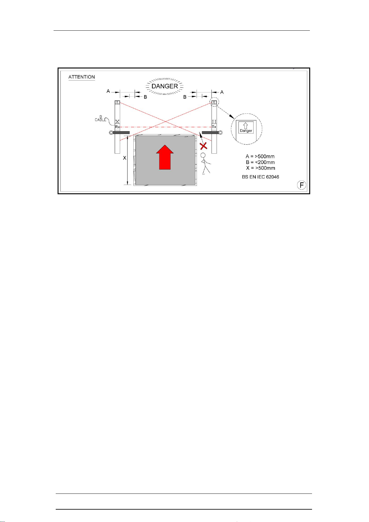
Figure F –Pallet Load Positioning
Figure F shows pallet load positioning on the conveyor relative to the transmitter
and receiver heads (note distances for A and B)
Ensure that the pallet when entering and exiting the self-muting safety light curtain
system is central on the conveyor. The distance for A and B to avoid ‘trapping’or
‘crushing’hazards and preventing entry during the muted condition should all be
considered in-line with the guidance within BS EN IEC 62046:2018.
X shows the minimum pallet load size, 500mm in length.

8K3 Series Cross-Beam Mute Accessories Installation Guide
CD693/150120 Smartscan Ltd
8
Figure G –Operating requirements
❑Humidity <95%
❑Temperature range between 0°C and +50°C or -30°C and +30°C
❑Vibration: Frequency <55Hz Max. Movement <0.35mm
❑Do not use equipment in explosive atmospheres (contact the manufacturer for
further advice).
❑Noise generated by the equipment will never exceed 70 dB
Environmental factors can affect the operation of a safety light curtain and proper
consideration should be taken into account for mounting a system where fog, rain,
smoke, dust, large temperature fluctuations etc. is a consideration.
Safety light curtains do not protect personnel from chemicals, heat, gases,
radiation, flying parts etc. as they are not a physical barrier.
The owner/provider must carry out a Risk Assessment and provide machine
operators instruction for the use of the safety light curtain on the machinery.
The 8K3 series safety light curtain can be configured with either the ‘L’ type (exit
only or a ‘T’ type (entry / exit) system.
The ‘L’ muting module configuration shown above is for out-feed zones ONLY. It
operates in a cross-beam muting beam configuration, the distance between the
Transmitter (TX) and Receiver (RX) should not exceed 3.5 metres.
The inverted ‘T’ shape muting module configuration shown above is for infeed and
infeed/outfeed positions. It operates in a cross-beam muting beam configuration,
the distance between the Transmitter (TX) and Receiver (RX) should not exceed
3.5 metres.

8K3 Series Cross-Beam Mute Accessories Installation Guide
CD693/150120 Smartscan Ltd
9
Heater options are available for application environments like cold stores.
Reset devices must be located such that the danger area can be seen to be clear
of persons before the system is activated. The reset device should also be
positioned so as not to be accessible from inside the danger area.
Activate Switch Electrical Connection
Activate switch - (F7). Connect the red/white wire in cable B to a normally open
switch contact. Connect the other side of the switch contact to +24V DC. The
switch could either be a spring return to off key switch or push button.
Mode - (F8) Connect the black/white wire in cable B to 0V DC, or for exit only
system where the mute delay-off timer is required to +24V DC.
8K3 Series Cross-Beam Mute Accessories Installation Guide
CD693/150120 Smartscan Ltd
10
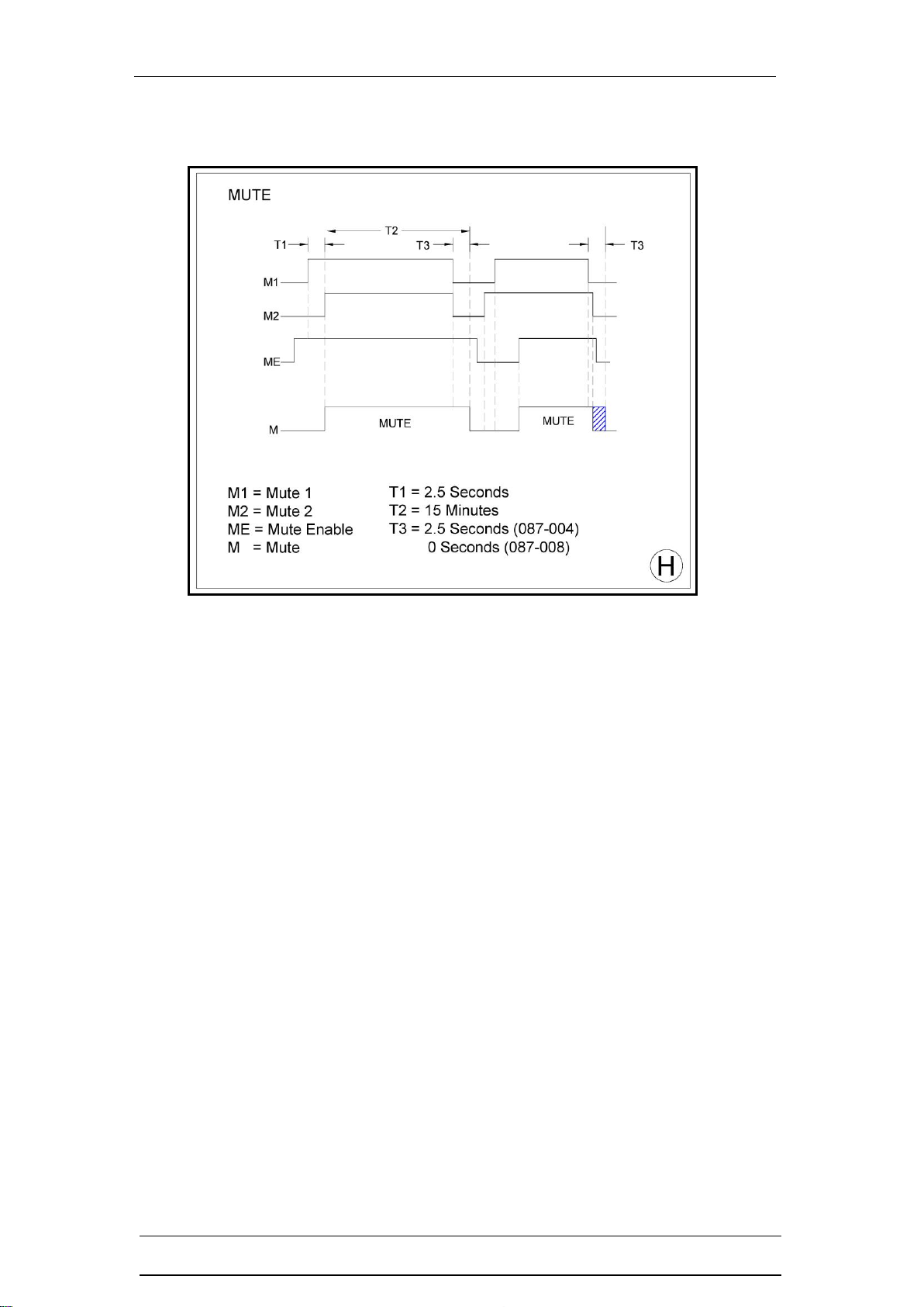
Figure H –Muting Timer Sequence
The timer diagram above shows the mute timer sequence for the ‘L’shape Exit
only cross-beam muting system, with and without the mute off delay time and the
inverted ‘T’shape Entry/Exit (bi-directional) cross-beam muting system.
Cross-beam Control Timers
T1 (Mute 1 and Mute 2 Disparity Time) = Maximum time allowed between
activation of signals mute 1 (M1) and mute 2 (M2) prior to the pallet load entering
the safety light curtain.
T2 (Mute Time Out Period) = A maximum pre-determined time the safety light
curtain will remain in a muted condition. Following this timed period, if the pallet
load is still interrupting the mute beams or the safety light curtain beams the
OSSDs will de-energise thus initiating a stop condition. Providing the pallet clears
the safety light curtain before the maximum time T2 is exceeded then the
automatic transfer of the pallet will continue.
T3 (Mute Off Delay Time) = This function can be used for the ‘L’shape Exit
system only and MUST NOT be used for the inverted ‘T’Entry/Exit system. A
predetermined time that the safety light curtain will remain in a muted condition
following de-activation of one or both of the mute signals.
Software version example
The standard 8K3 Series is supplied with ‘E’ version software, for example
087E903. This provides the following functions for cross-beam muting timers,
T1 = 2.5 Sec T2 = 15 min T3 = 2.5 Sec.
8K3 Series Cross-Beam Mute Accessories Installation Guide
CD693/150120 Smartscan Ltd
11
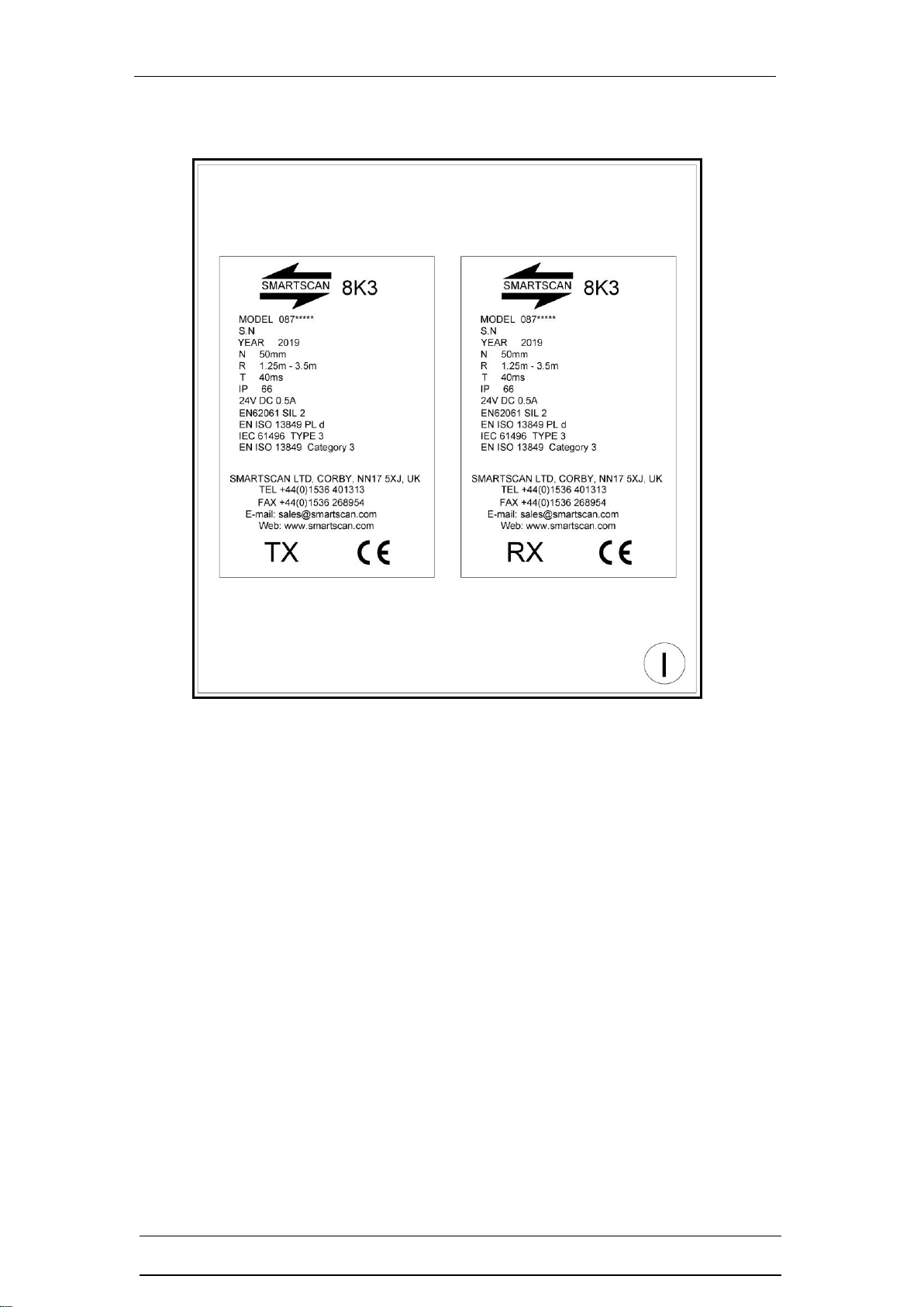
Figure I –Identification Labels
Examples are shown below of the identification labels that are affixed to the
bottom of the transmitter (TX) and receiver (RX) columns.
8K3 Series Cross-Beam Mute Accessories Installation Guide
CD693/150120 Smartscan Ltd
12
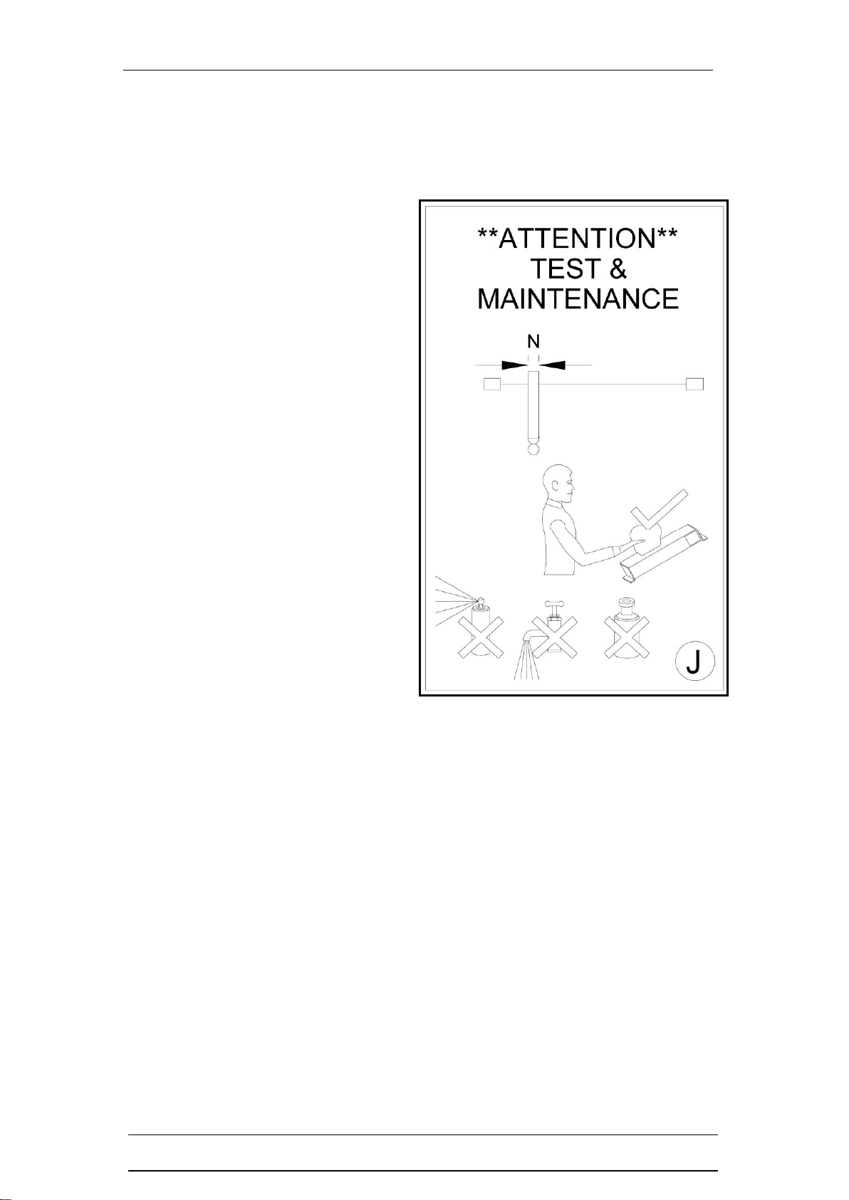
Figure J –Test and Maintenance
Testing the mute accessories with a test piece
The test procedure should be carried
out frequently as indicated by the
risk assessment for the particular
installation.
A test must be carried out at the
initial installation and prior to the
machine start-up.
Smartscan Ltd recommends the test
should be carried out daily prior to
normal operation of the machine.
Any changes to the configuration of
the safety light curtain must be
followed by testing to check the
system is still working correctly.
Regular function checking of the
safety light curtain as well as at initial
installation is required as part of the
test and maintenance process.
The operating instructions for the
safety light curtain and machine
must be made available for the
operator and those responsible for installation, maintenance and safety control at
all times.
Power-up the 8K3 series safety light curtain and activate the output switching
circuits to an ON condition.
Cross-Beam
Insert a test piece of appropriate size into the detection zone of one of the mute
sensors. After 2.5 seconds the safety outputs will turn OFF. Repeat this
operation for the second mute sensor, again the outputs should turn OFF within
2.5 seconds.

8K3 Series Cross-Beam Mute Accessories Installation Guide
CD693/150120 Smartscan Ltd
13
Maintenance
The Transmitter (TX) and Receiver (Rx) windows should be cleaned regularly as
indicated on the Installation Sheet, Figure K.
Dirt build-up or scratching on the windows may lead to
intermittent tripping or a totally blocked condition of the light
curtain. Clear adhesive tape may be applied to the windows
of curtains in dirty or abrasive conditions. Renew the clear
adhesive tape periodically.
Dust particles can be attracted to the Perspex window due to
static charges. This can be prevented by the use of an antistatic plastic cleaner
and antistatic cloth.
Clean the windows with a clean damp cloth using a mild
detergent. Never use abrasive, corrosive cleaners or
spray detergents.
During the maintenance inspection of the safety device and the danger area
checks include, damage and general wear, connection cables and the electrical
connections.
Check the mountings and physical extrusion, Perspex.
Access to the danger point should be through the infrared field of the safety light
curtain only.
See also the Operation Cycle checks within this document.
8K3 Series Cross-Beam Mute Accessories Installation Guide
CD693/150120 Smartscan Ltd
14
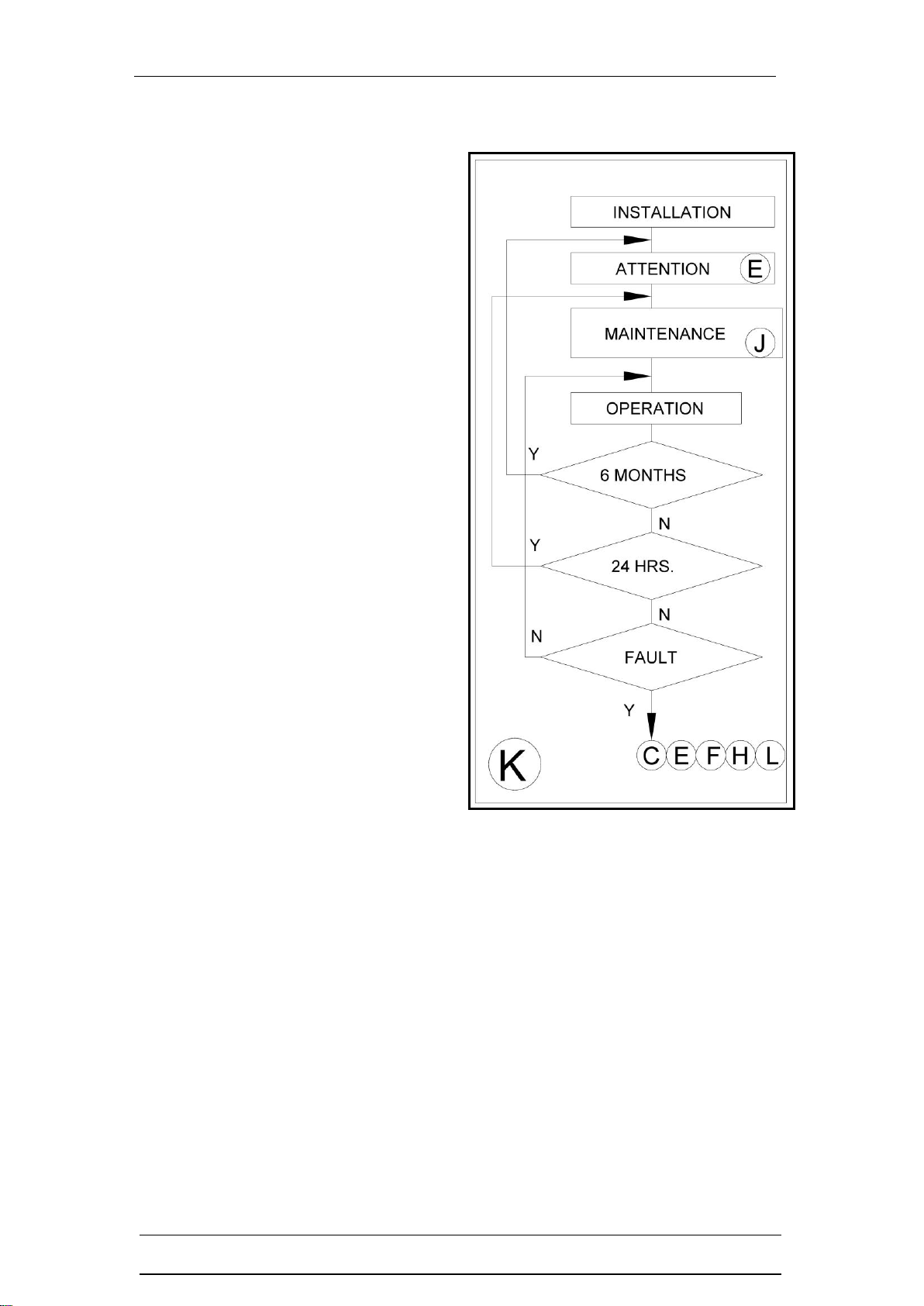
Figure K –Operation Cycle
❑Before installation read and
understand the Installation Sheet
provided paying particular attention
to the information provided in
Figures C, E and I
❑Refer to Fig. J for test and
maintenance procedures
❑Every 24 hours carry out tests as
indicated in Fig. J
❑Every 6 months check the entire
installation including those on the
installation sheet for the safety
light curtain.
❑If the equipment fails to operate as
intended check through the entire
installation sheet.

8K3 Series Cross-Beam Mute Accessories Installation Guide
CD693/150120 Smartscan Ltd
15
Figure L –Product Return Procedure
If a fault occurs that cannot be resolved or the equipment is damaged return the
equipment to the nearest Smartscan distributor or Smartscan Ltd. Indicate the
nature of the fault and the symptoms displayed on the form provided.
Note Please ensure that returned guards (Transmitter and Receiver heads)
are matching serial number pairs.
8K3 Series Cross-Beam Mute Accessories Installation Guide
CD693/150120 Smartscan Ltd
16
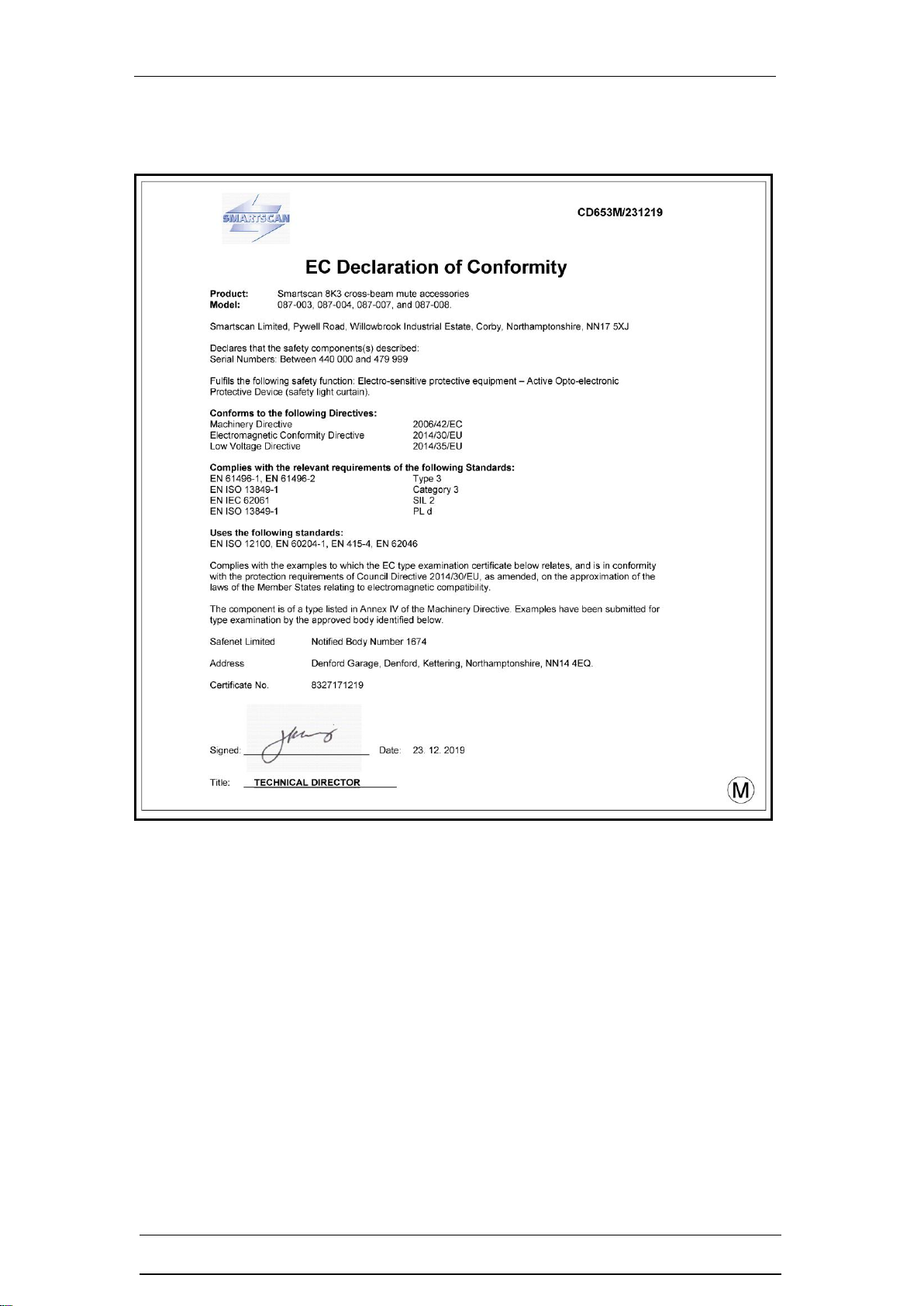
Figure M –Declaration of Conformity

8K3 Series Cross-Beam Mute Accessories Installation Guide
CD693/150120 Smartscan Ltd
17
Figure N –Glossary of Words and Language Translation
Table of contents
Other SMART-SCAN Safety Equipment manuals


