SMART-SCAN C4 compact ME Series User manual

C4 compact ME SERIES
SAFETY LIGHT CURTAINS
INSTALLATION GUIDE
MACHINERY SAFETY SYSTEMS

Safety Light Curtain – C4 compact ME Series
Installation Guide
FileNumber:CD1011
page 2 Date: 12 April, 2017
SMARTSCAN TW Ltd
2F, No. 5, 10th Road, Taichung Industrial park,
Taichung City, Taiwan, R.O.C.
TEL: 886 - 4 - 23598885
FAX: 886 - 4 - 23599423
Important!
Failure to read and follow the instructions provided on the Installation Sheet and
Installation Guide can lead to the incorrect application or use of the C4 compact ME series
safety light curtain. This could lead to personal injury and damage to equipment. All
applicable machine safety standards and regulations should be taken into account when
installing the C4 compact ME series safety light curtain or any machine safety product.
The Installation Sheet and Installation Guide can be downloaded from our web site at
www.smartscan.com.tw
The C4 compact ME series Safety Light Curtain Installation Guide (CD1011) is subject to
change without notice. SMARTSCAN TW Ltd shall not be held responsible for technical
errors, editorial errors or omissions contained herein, nor for incidental or consequential
damages resulting from the use of this material.
© 2017 SMARTSCAN TW Ltd. All Rights Reserved. Unless explicitly stated
otherwise, all rights including those in copyright in the content of this document are owned
by or controlled for these purposes by SMARTSCAN TW Ltd.
Except as otherwise expressly permitted under copyright law or SMARTSCAN TW Ltd,
reproduction of the document or alteration of this document may not be carried out in any
way without first obtaining SMARTSCAN TW Ltd's written permission.

Safety Light Curtain – C4 compact ME Series
Installation Guide
FileNumber:CD1011
page 3 Date: 12 April, 2017
Contents:
FigureA–Unpacking.....................................................................................................................................4
FigureB–MountingInformation..................................................................................................................5
FigureC–DimensionalInformation..............................................................................................................6
FigureD–OperatingRequirements..............................................................................................................7
FigureE–ImportantInstallationConsiderations..........................................................................................9
FigureF–ElectricalConnections–ResetMode(Manual/Latched)............................................................11
PowerSupply.......................................................................................................................................12
Manual(Latched)Reset.......................................................................................................................12
ExternalDeviceMonitoring(EDM)......................................................................................................13
SafetyOutputsOSSD1andOSSD2.......................................................................................................13
CommunicationLink............................................................................................................................14
FigureG–ElectricalConnections–AutoResetMode................................................................................15
PowerSupply.......................................................................................................................................16
AutomaticReset...................................................................................................................................16
ExternalDeviceMonitoring(EDM)......................................................................................................17
SafetyOutputsOSSD1andOSSD2.......................................................................................................17
CommunicationLink............................................................................................................................18
FigureH–IdentificationLabels...................................................................................................................19
FigureI–StatusandDiagnosticIndication..................................................................................................20
Receiver(RX)StatusIndicators............................................................................................................20
Transmitter(TX)DiagnosticDisplayPanel...........................................................................................21
Transmitter(TX)StatusIndicators........................................................................................................23
FigureJ–TestandMaintenance.................................................................................................................24
Testingthesafetylightcurtainwiththetestpiece..............................................................................24
Maintenance........................................................................................................................................25
FigureK–OperationCycle...........................................................................................................................26
FigureL–ProductReturnProcedure...........................................................................................................27
FigureM–ModelList..................................................................................................................................28
FigureN–DeclarationofConformity..........................................................................................................38
FigureO–GlossaryofWordsandLanguageTranslation............................................................................39
Appendix1–ImportantSafetyInformation................................................................................................40
Appendix2–Certifications..........................................................................................................................41
Appendix3–Mirrors...................................................................................................................................42
Appendix4–SpecificationTable.................................................................................................................46
Notes............................................................................................................................................................48

Safety Light Curtain – C4 compact ME Series
Installation Guide
FileNumber:CD1011
page 4 Date: 12 April, 2017
C4 compact ME Series (Model No. C4B-xxx M / E, C4A-xxx M / E) Safety Light Curtain
Installation Sheet (CD1011/120417)
Figure A – Unpacking
Remove all packaging material and retain it
Locate and keep the delivery note
Inspect all items for transit damage
Match goods supplied to those specified on the delivery note
Keep the Installation Sheet in a safe place
Each C4 compact ME series supplied would normally include:
Safety Light curtain
Test piece
Installation sheet
Service questionnaire form
Storage requirements:
Humidity - <95%
Temperature range between –20°C and +70°C
Safety Light Curtain – C4 compact ME Series
Installation Guide
FileNumber:CD1011
page 5 Date: 12 April, 2017
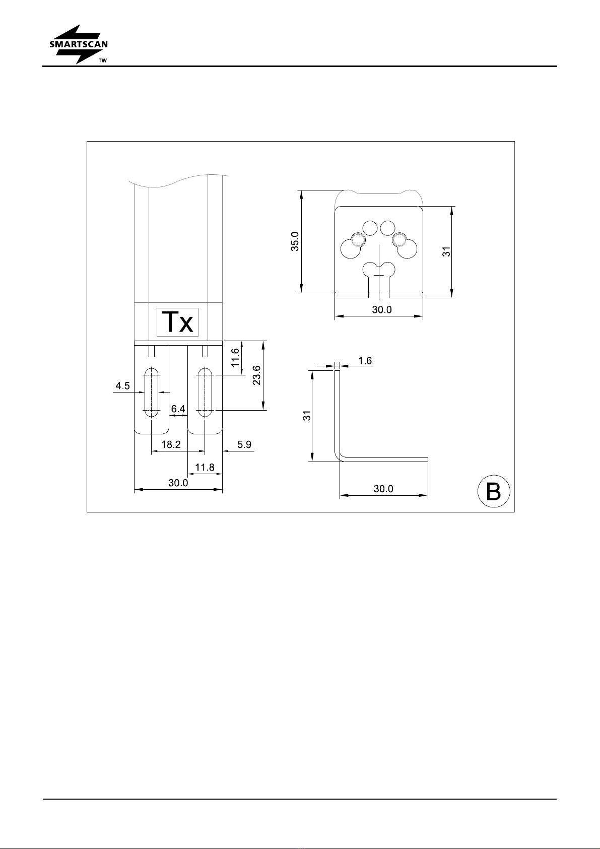
Figure B – Mounting Information
The C4 compact ME series comes with mounting brackets as standard. The mounting brackets
are located at the ends of the safety light curtain as shown above. The mounting bracket may
be fixed at 90 degrees, with a +/-5˚adjustment.
Use 4mm bolts for mounting and ensure they are fixed so as to prevent any movement or
loosening of the safety light curtain.
The C4 compact ME series does not use cable connectors. Both the transmitter (Tx) and
receiver (Rx) units come complete with 5m cables attached.
Transmitter = 3 core cable.
Receiver = 7 core cable.
Safety Light Curtain – C4 compact ME Series
Installation Guide
FileNumber:CD1011
page 6 Date: 12 April, 2017
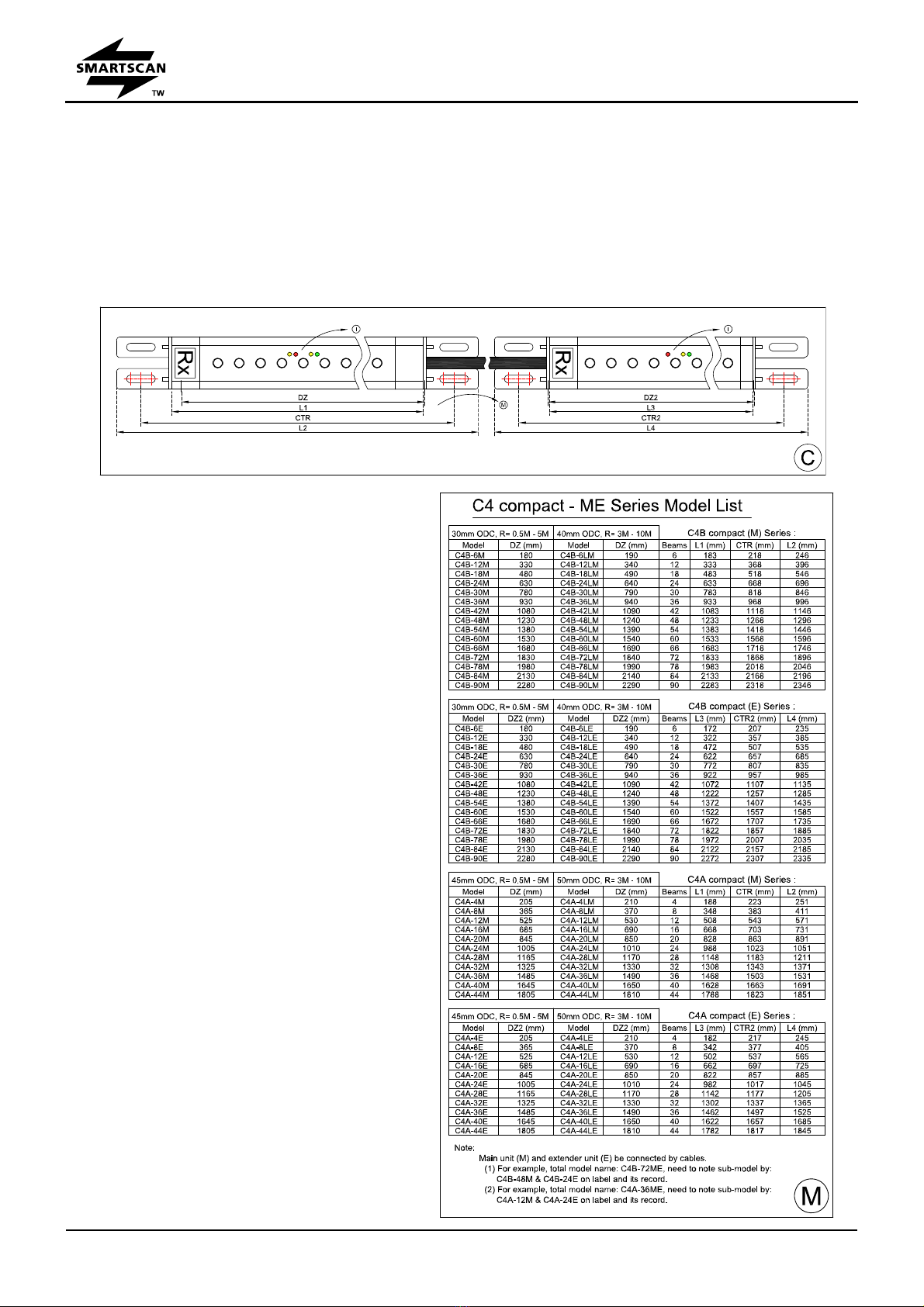
Figure C – Dimensional Information
Figure C describes important parameters associated with the safety light curtain such as
detection zone width (DZ).
Measurements are shown for the safety
light curtain’s overall length (including
mounting brackets), fixing centres and
detection zone width.
The detection zone width (DZ, DZ2) or
protected height is needed to select the
appropriate length to cover the access
area.
The light curtain’s dimensions including the
mounting bracket are overall length (L) x
30mm width x 35mm depth.
The overall length (L2, L4), mounting
centres (CTR, CTR2) and detection zone
width (DZ, DZ2) in millimeters for each
individual model is listed in Figure M.
Safety Light Curtain – C4 compact ME Series
Installation Guide
FileNumber:CD1011
page 7 Date: 12 April, 2017
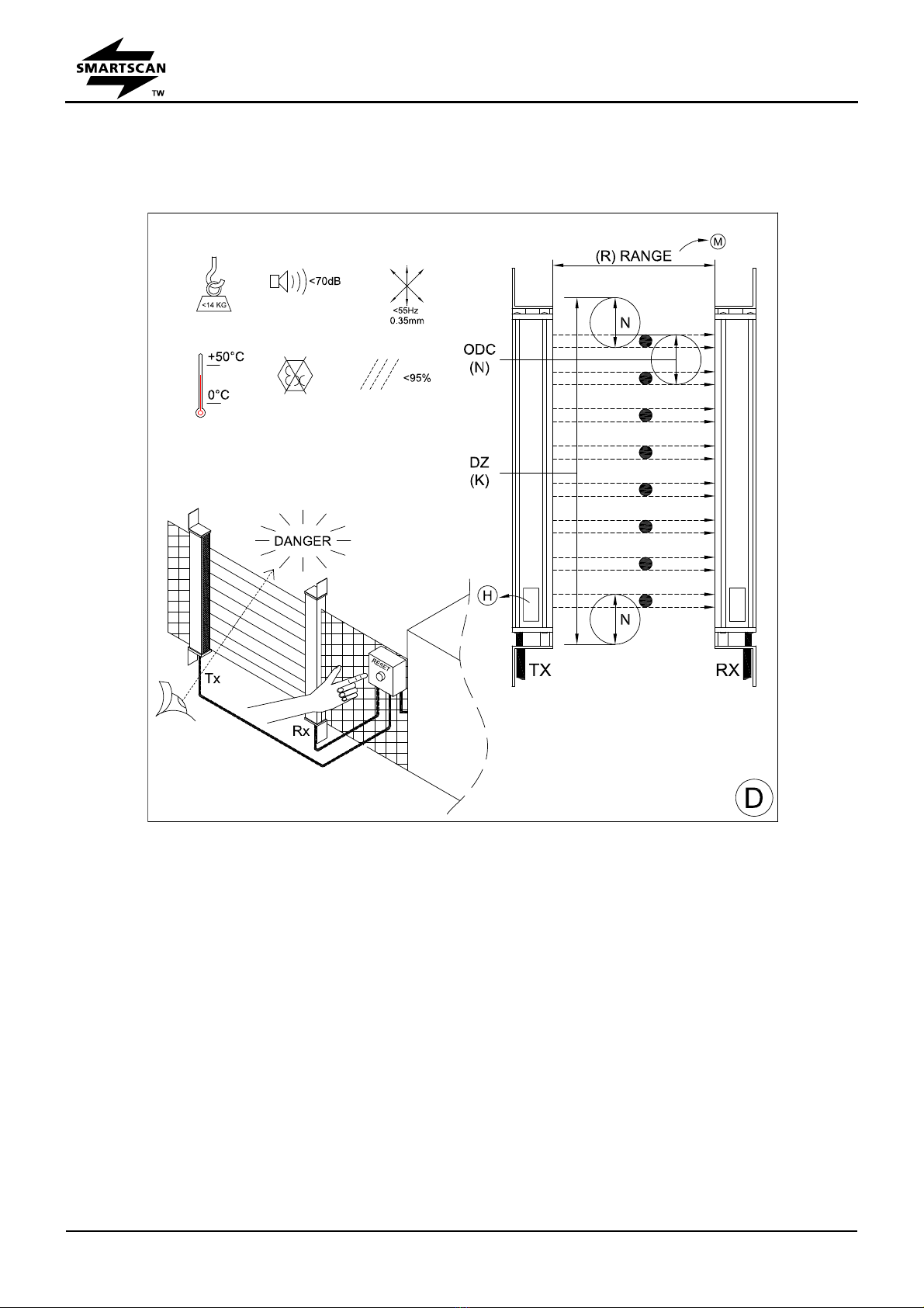
Figure D – Operating Requirements
Humidity <95%
Temperature range between 0°C and +50°C
Vibration: Frequency <55Hz Max. Movement <0.35mm
Do not use equipment in explosive atmospheres (contact the manufacturer for further
advice).
Detection Zone width (DZ)
The detection zone width or protected height must be of a suitable size for each application to
prevent personnel access to the danger area. This can be over, under or around the light
curtains detection zone.

Safety Light Curtain – C4 compact ME Series
Installation Guide
FileNumber:CD1011
page 8 Date: 12 April, 2017
Object Detection Capability (ODC)
The minimum size of object guaranteed to be detected when placed in the light curtain’s infrared
sensing field. A test piece of appropriate size is provided to test that the light curtain object
detection capability is within the parameter specified for the particular model number.
Transparent objects are not detected.
Range
This is the maximum scanning range of the light curtain between the Transmitter (TX) head and
Receiver (RX) head. Ensure the light curtain is capable of satisfying the range requirement for
the particular application it is being used for.
Reset Location
Reset devices must be located such that the danger area can be seen to be clear of persons
before the system is activated. The reset device should not be accessible from inside the
danger area.
Environmental factors can affect the operation of a safety light curtain and proper consideration
should be taken into account for mounting a system where fog, rain, smoke, dust, large
temperature fluctuations etc is a consideration.
Safety light curtains do not protect personnel from chemicals, heat, gases, radiation, flying parts
etc. They are not a physical barrier.
The machine operators must be instructed in the use of the safety light curtain by the
owner/provider of the machinery.
Safety Light Curtain – C4 compact ME Series
Installation Guide
FileNumber:CD1011
page 9 Date: 12 April, 2017
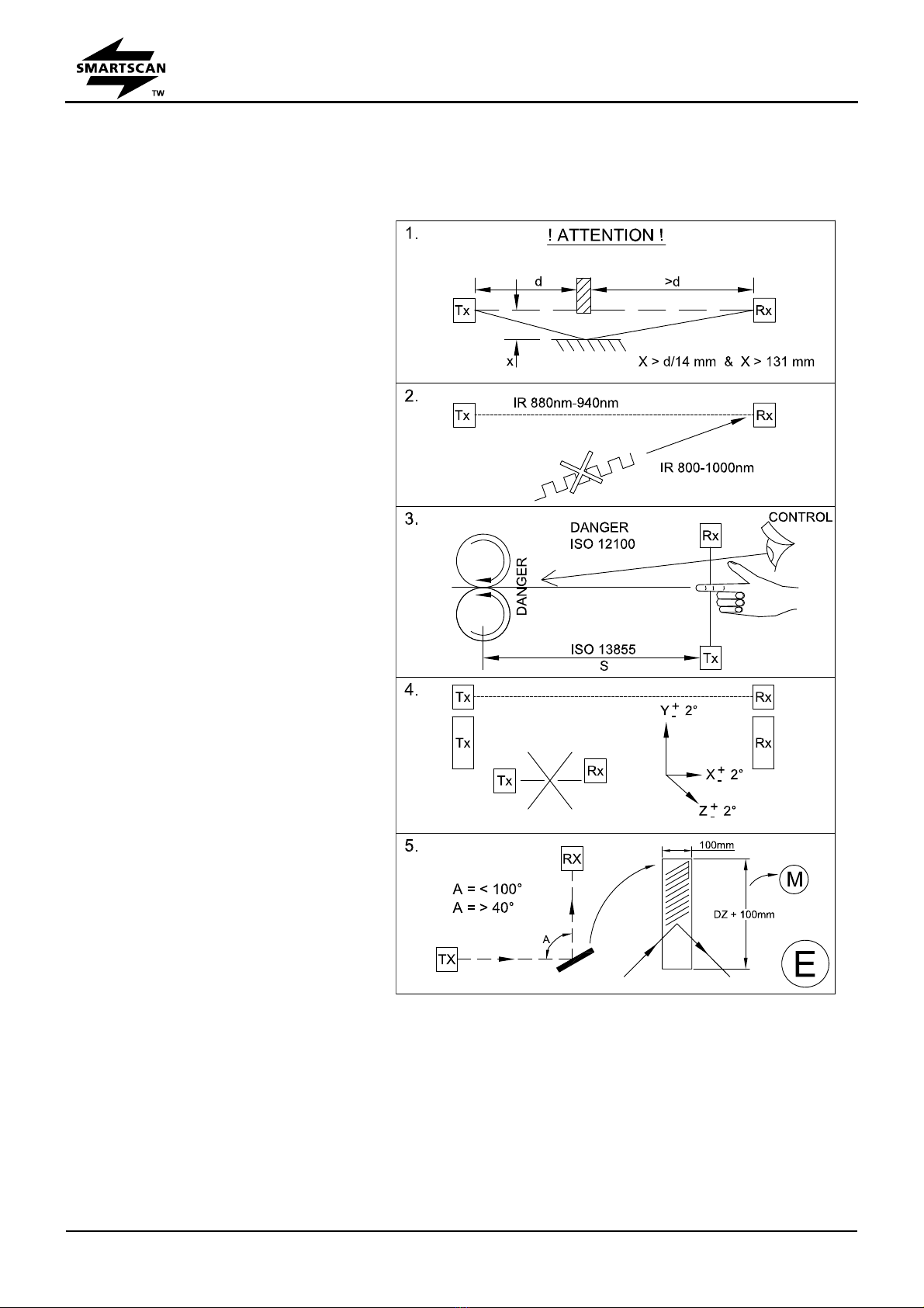
Figure E – Important Installation Considerations
1. Consider reflective surfaces that
may give rise to an optical ‘short
circuit’ from the direct path of the
safety light curtain’s infrared
beams as shown in the first
illustration of Fig. E. To ensure
the safety light curtain is mounted
far enough away from reflective
surfaces use the formula provided
to calculate the minimum distance
(X) between the light curtain and
reflective surface.
2. To prevent intermittent tripping of
the safety light curtain ensure that
extraneous infrared energy
between 800 and 1000
nanometers is not directed towards
the Perspex window of the receiver
unit (RX). Extraneous sources
would include infrared sensors,
infrared remote controls, scanning
systems or sunlight.
3. Ensure the mounting position of
the safety light curtain in respect to
the nearest danger point meets the
requirements of European
Standard ISO 13855. The Separation distance of the safety light curtain from the danger
point of the machine must be met at all times for safe operation. In order for the machine to
be guarded by the safety light curtain, the machine must be capable of stopping at any point
in the machine cycle.
To prevent personnel from reaching the danger point of the machine additional mechanical
guarding may be required so that any access has to be through the sensing field of the safety
light curtain. The safety light curtain must be positioned so as to prevent any overreach or

Safety Light Curtain – C4 compact ME Series
Installation Guide
FileNumber:CD1011
page 10 Date: 12 April, 2017
under reach to the danger point. It must not be possible to stand between the safety light
curtain and the danger point.
The protection afforded by the safety light curtain should correspond to the machine Risk
Assessment under ISO 12100 for the machine being guarded.
4. Ensure the light curtain transmitter (TX) and receiver (RX) units are mounted accurately
in-line with each other and are both perpendicular and parallel to each other within the
parameters shown for each axis.
5. If utilising mirrors to deflect the light curtain ensure the mirror length is 50mm longer at either
end of the light curtain detection zone width and mounted centrally to the zone. To ensure
reliable operation the light curtain deflection angle (A) from the mirror must not be less than
40 degrees or greater than 100 degrees. (See Appendix 3)

Safety Light Curtain – C4 compact ME Series
Installation Guide
FileNumber:CD1011
page 11 Date: 12 April, 2017
Figure F – Electrical Connections – Reset Mode (Manual/Latched)

Safety Light Curtain – C4 compact ME Series
Installation Guide
FileNumber:CD1011
page 12 Date: 12 April, 2017
Power Supply
Use a regulated power supply +24V DC ±10% fused at 1.5A. The C4 compact ME series light
curtain current consumption is rated at 0.5A + load current of the OSSDs. The Brown wire on
both the Transmitter (TX) and Receiver (RX) head cables must be connected to 24V DC (L+).
The Blue wire on both the Transmitter (TX) and Receiver (RX) head cables must be connected to
0V DC (L-).
Before the power supply is applied to the light curtain ensure both TX and RX heads are aligned
correctly.
Manual (Latched) Reset
The C4 compact ME series provides a manual (latched) reset for applications where it is a
requirement that the safety outputs cannot be reinstated without the operator first checking that
the dangerous area is clear of personnel and therefore safe. The reset switch must also be
located so that the operator cannot reset the light curtain from inside the dangerous area.
Warning The shield on both the Transmitter (TX) and Receiver (RX) head
cables must be connected to Earth (PE).
Warning 0V (L-) of the power supply unit (PSU) must be connected to Earth
(PE). No signal should exceed +24V DC ±10% (L+) or be less than 0V (L-)
Warning Do not disconnect the cables from the Transmitter (TX) or Receiver
(RX) head with the power still connected to the C4 compact ME series light
curtain.
Any wiring or re-wiring of the light curtain must be done with the power supply
disconnected.
Any input or output signals that are not being used must be terminated safe.
The machine must be disconnected during electrical installation to ensure no
inadvertent start up of the machine occurs.
The connection cables must be not be routed with high-voltage cables, e.g.

Safety Light Curtain – C4 compact ME Series
Installation Guide
FileNumber:CD1011
page 13 Date: 12 April, 2017
The reset switch must be a Normally Open spring-return contact block, either push button or key
switch, depending on the customer risk assessment. The Green wire on the Receiver (RX)
head cable needs to be connected to one side of the Normally Open contact block and the other
side to 24V DC (L+). The light curtain will only reset on the trailing edge of the switch.
External Device Monitoring (EDM)
An External Device Monitoring input facility is provided for monitoring the customers’ external
Final Switching Devices (FSD) to ensure those devices respond in unison with the safety outputs
each and every time the light curtain is interrupted. Failure of the external Final Switching
Device (FSD) during monitoring will not allow the safety light curtain’s output OSSDs to reset.
The EDM Yellow wire on the Receiver (RX) head should be connected via a normally closed (NC)
contact of the external Final Switching Device (FSD) being monitored. The other side of the
contact is connected to 24V DC.
If the EDM is not being used the Yellow wire must be connected to a permanent 24V DC (L+).
The top yellow LED indicator located on the Receiver (RX) head shows the EDM status.
Safety Outputs OSSD1 and OSSD2
Two independent (PNP) electronic switching failsafe signal outputs (OSSDs) are provided for the
machine safety circuit. Interruption of the safety light curtains infrared sensing field will cause
the OSSDs to go to an OFF state and initiate a machine stop condition.
The connections are provided via the Grey wire (OSSD1) and the Orange wire (OSSD2) on the
Receiver (RX) head cable.
Outputs ON = +24V DC (Light curtain clear)
Outputs OFF = 0V DC (Light curtain blocked)
The electronic outputs are monitored and rated at a maximum switching rating of 24V DC,
500mA. LED indicators located on the Receiver (RX) head show the status of the OSSDs.
Green LED ON = OSSD1 and OSSD2 active ON
Red LED ON = OSSD1 and OSSD2 inactive OFF
Yellow LED ON = EDM ON Yellow LED OFF = EDM OFF

Safety Light Curtain – C4 compact ME Series
Installation Guide
FileNumber:CD1011
page 14 Date: 12 April, 2017
Communication Link
The Transmitter (TX) and Receiver (RX) heads communicate via DATA-Link. The Violet wire
from the Transmitter (TX) head cable must be connected to the Violet wire from the Receiver (RX)
head cable.
Warning The Data wires are communication links and have DATA-Link voltage
levels (+ 24V). They MUST NOT be connected to any other voltage source.
The maximum total cable length from the Transmitter (TX) head to the Receiver
(RX) head must not exceed 40m.

Safety Light Curtain – C4 compact ME Series
Installation Guide
FileNumber:CD1011
page 15 Date: 12 April, 2017
Figure G – Electrical Connections – Auto Reset Mode

Safety Light Curtain – C4 compact ME Series
Installation Guide
FileNumber:CD1011
page 16 Date: 12 April, 2017
Power Supply
Use a regulated power supply +24V DC ±10% fused at 1.5A. The C4 ME compact series light
curtain current consumption is rated at 0.5A + load current of the OSSDs. The Brown wire on
both the Transmitter (TX) and Receiver (RX) head cables must be connected to 24V DC (L+).
The Blue wire on both the Transmitter (TX) and Receiver (RX) head cables must be connected to
0V DC (L-).
Before the power supply is applied to the light curtain ensure both TX and RX heads are aligned
correctly.
Automatic Reset
The automatic reset mode allows the safety light curtain to be reset automatically, that is, on a
blockage of the safety light curtain’s sensing field it will turn off the safety outputs (OSSDs).
Removing the blockage from the sensing field of the light curtain will re-activate and turn on the
safety outputs (OSSDs). The configuration of the safety light curtain in the auto reset mode will
Warning The shield on both the Transmitter (TX) and Receiver (RX) head
cables must be connected to Earth (PE).
Warning 0V (L-) of the power supply unit (PSU) must be connected to Earth
(PE). No signal should exceed +24V DC ±10% (L+) or be less than 0V (L-)
Warning Do not disconnect the cables from the Transmitter (TX) or Receiver
(RX) head with the power still connected to the C4 compact ME series light
curtain.
Any wiring or re-wiring of the light curtain must be done with the power supply
disconnected.
Any input or output signals that are not being used must be terminated safe.
The machine must be disconnected during electrical installation to ensure no
inadvertent start up of the machine occurs.
The connection cables must be not be routed with high-voltage cables, e.g.

Safety Light Curtain – C4 compact ME Series
Installation Guide
FileNumber:CD1011
page 17 Date: 12 April, 2017
depend on the customer’s risk assessment for the machine.
The Yellow wire on the Receiver (RX) head cable must be connected to 0V DC (L-) and the
Green wire on the Receiver (RX) head to the 24V DC (L+).
External Device Monitoring (EDM)
An External Device Monitoring input facility is provided for monitoring the external Final
Switching Devices (FSD) to ensure those devices respond in unison with the safety outputs each
and every time the safety light curtain is interrupted. Failure of the external Final Switching
Device during monitoring will not allow the safety light curtain to reset.
In Auto reset mode the EDM function is connected via the Green wire on the Receiver (RX) head
via a normally closed (NC) contact of the external final switching device (FSD) being monitored.
The other side of the contact(s) is connected to 24V DC.
If the EDM is not being used the Green wire must be connected to a permanent 24V DC (L+).
The bottom yellow LED indicator located on the Receiver (RX) head shows the EDM status.
Safety Outputs OSSD1 and OSSD2
Two independent (PNP) electronic switching failsafe signal outputs (OSSDs) are provided for the
machine safety circuit. Interruption of the safety light curtains infrared sensing field will cause
the OSSDs to go to an OFF state and initiate a machine stop condition.
The connections are provided via the Grey wire (OSSD1) and the Orange wire (OSSD2) on the
Receiver (RX) head cable.
Outputs ON = +24V DC (Light curtain clear)
Outputs OFF = 0V DC (Light curtain blocked)
The electronic outputs are monitored and rated at a maximum switching rating of 24V DC,
500mA. LED indicators located on the Receiver (RX) head show the status of the OSSDs.
Green LED ON = OSSD1 and OSSD2 active ON
Red LED ON = OSSD1 and OSSD2 inactive OFF
Yellow LED ON = EDM ON Yellow LED OFF = EDM OFF

Safety Light Curtain – C4 compact ME Series
Installation Guide
FileNumber:CD1011
page 18 Date: 12 April, 2017
Communication Link
The Transmitter (TX) and Receiver (RX) heads communicate via DATA-Link. The Violet wire
from the Transmitter (TX) head cable must be connected to the Violet wire from the Receiver (RX)
head cable.
Warning The Data wires are communication links and have DATA-Link voltage
levels (+ 24V). They MUST NOT be connected to any other voltage source.
The maximum total cable length from the Transmitter (TX) head to the Receiver
(RX) head must not exceed 40m.
Safety Light Curtain – C4 compact ME Series
Installation Guide
FileNumber:CD1011
page 19 Date: 12 April, 2017
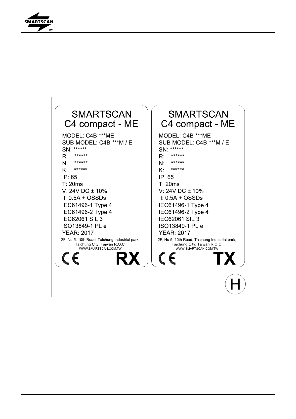
Figure H – Identification Labels
Examples are shown below of the identification labels that are affixed to the bottom of the
transmitter (TX) and receiver (RX) columns.
Safety Light Curtain – C4 compact ME Series
Installation Guide
FileNumber:CD1011
page 20 Date: 12 April, 2017
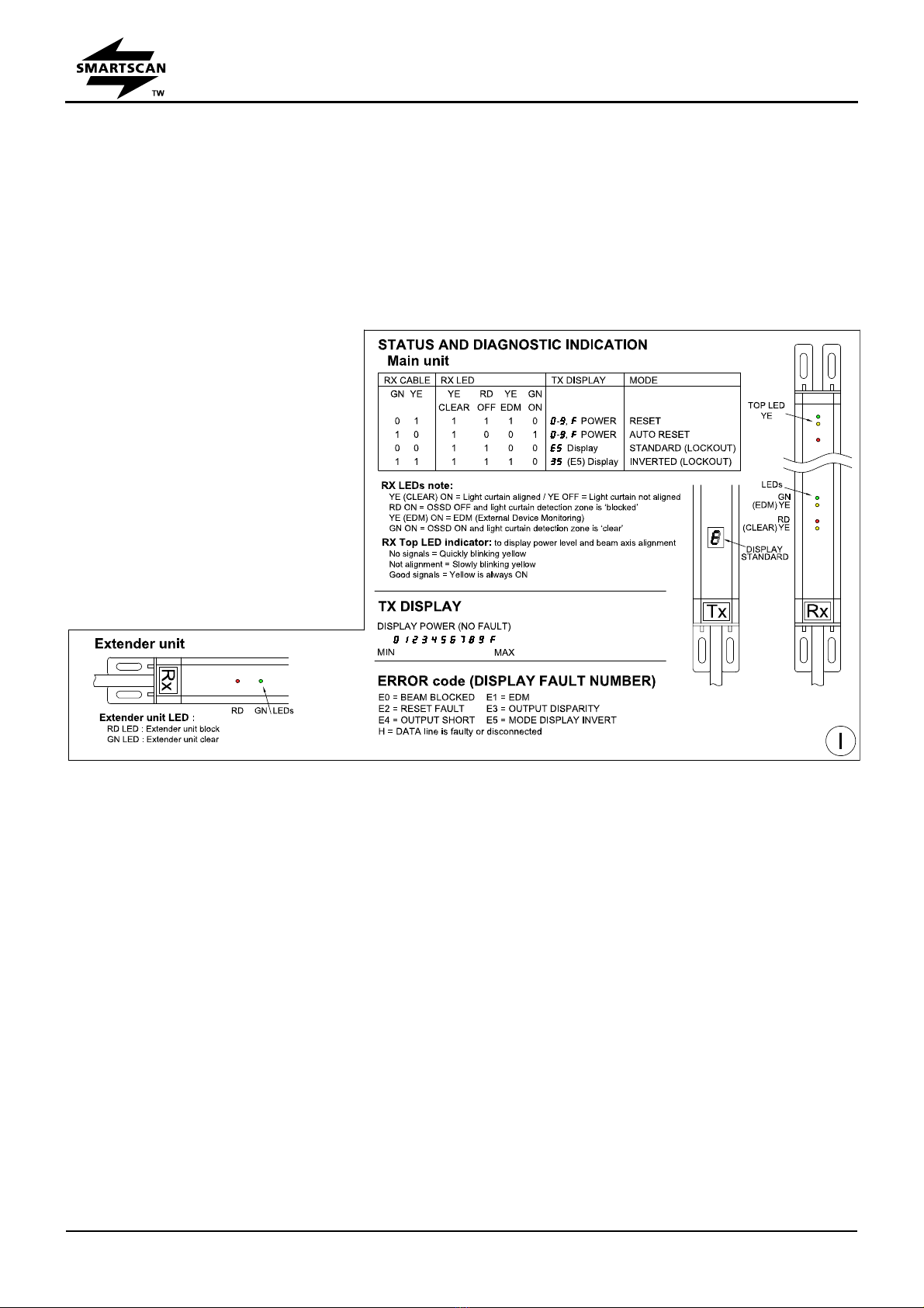
Figure I – Status and Diagnostic Indication
The C4 compact ME series has status indication LEDs on the Receiver (RX) head and a 7
segment display panel located at the bottom of the Transmitter (TX) head. They provide a
range of functions to help in the set-up of the safety light curtain and in fault diagnosis.
Receiver (RX) Status Indicators
GREEN LED ‘on’ = Light curtain safety reset has been initiated and the OSSDs are in the on
state, (only when the light curtain detection zone is clear of any obstruction).
YELLOW LED ‘on’ = EDM (External Device Monitoring).
The Red LED provides two functions,
RED LED ‘on’ = Light curtain safety off. OSSD1 and OSSD2 are ‘OFF’ e.g. when the light curtain
detection zone is ‘blocked’.
RED LED ‘on’ = Power connected to the light curtain.
YELLOW LED ‘on’ = Light curtain aligned and LED off = Light curtain not aligned.
RX TOPALIGNED indicators:
Table of contents
Other SMART-SCAN Safety Equipment manuals


