Smarte SNX-16x16 X+ User manual

User Guide
Part No: SmartNet X+
SmartNet X+
16x16 AV Router/Extender
Model No:
SNX-16x16 X+

Edition 2, January 1, 2007
Copyright 2005 Smart-e (UK) Ltd.
Notice
The information contained in this document is subject to change without notice. Smart-e makes no war-
ranty of any kind with regard to this material, including but not limited to, implied warranties of merchant-
ability and fitness for particular purpose.
Smart-e will not be liable for errors contained herein or for incidental or consequential damages in connec-
tion with the furnishing, performance or use of this material.
No part of this document may be photocopied, reproduced , or translated into another language without
prior written consent from Smart-e (UK) Ltd.

Table of Contents
Introducing SmartNet X+
What‘s in the box…………………………………………………….. 1
What is SmartNet........................................................ 2
Why is SmartNet necessary.......................................... 2
How does SmartNet work ............................................ 2
Installation and Operation ...........................................3
SmartNet ................................................................... 3
System Considerations ................................................ 6
Receiver Options......................................................... 7
SLX-RX100 ................................................................. 8
SLX-RX100 V1.0.......................................................... 10
SLX-RX100 V4.0.......................................................... 12
SLX-RX200 ................................................................. 14
SLX-RX111 ................................................................. 19
Appendix ......................................................................23
Specifications ............................................................. 23
Cable connection information ....................................... 26
Limited warranty statement ......................................... 27
Introducing SmartNet
What‘s in the box?
Thank you for buying the SmartNet X+ AV Router/Extender. Depending on the configuration of your system
various quantities of the parts below may be included in your shipment.
If any of the accessories listed below are missing please contact the Smart-e dealer you purchased products
from or contact Smart-e customer support at:
+44 1483 283365
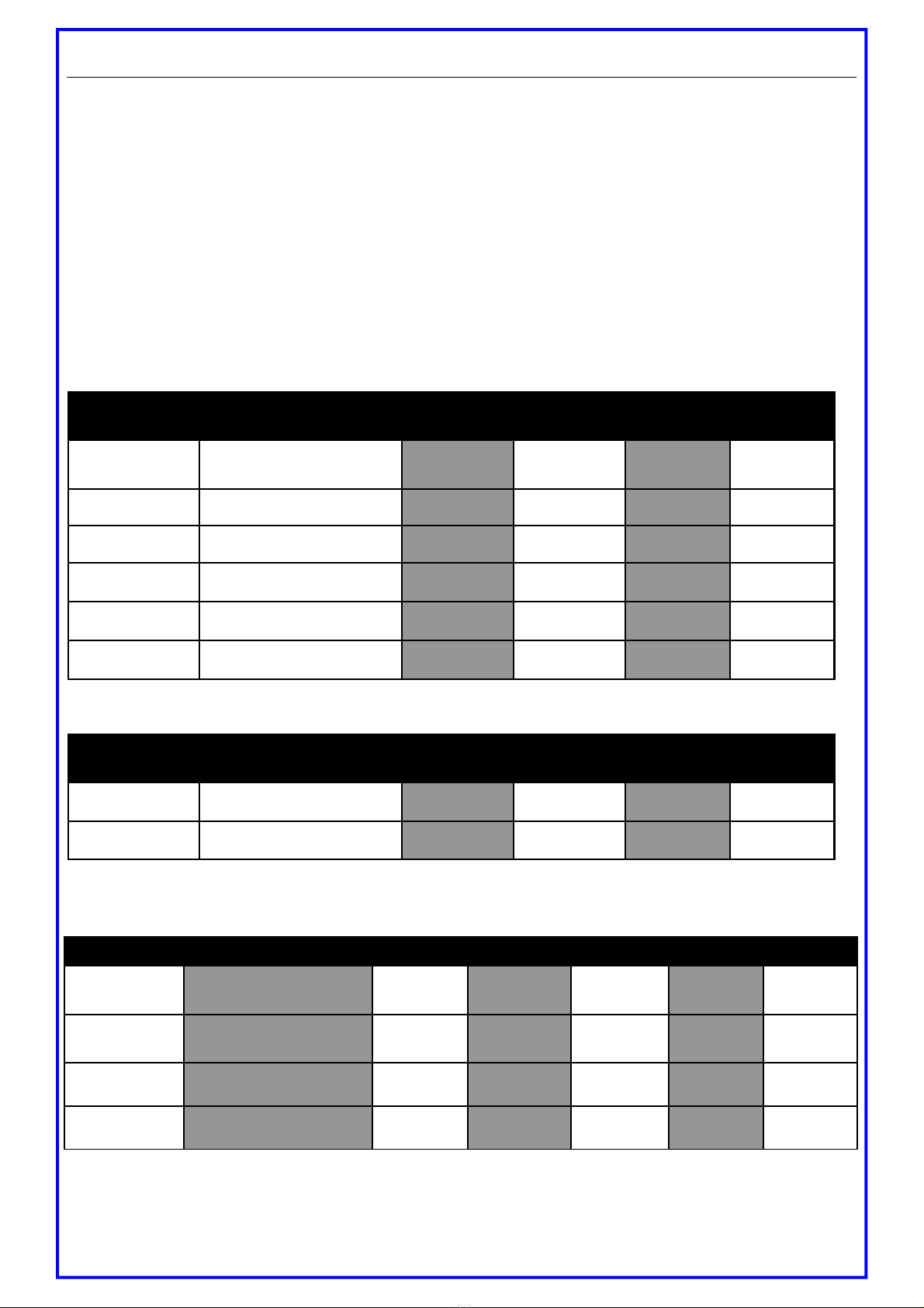
Item Description SNX-16x4
X+
SNX-16x8
X+
SNX-16x12
X+
SNX-16x16
X+
SNX-16x?? X+ 16 input router & cat 5
extender
Yes Yes Yes Yes
Outputs 1-4 Outputs enabled? Yes Yes Yes Yes
Outputs 5-8 Outputs enabled? No Yes Yes Yes
Outputs 9-12 Outputs enabled? No No Yes Yes
Outputs 13-16 Outputs enabled? No No No Yes
Mains Cable Standard PSU Mains Cable Yes Yes Yes Yes
If you ordered a SmartNet X+ Router/Extender
If you ordered Smart-e Receivers
Page 1
Item Description SNX-16x4
X+
SNX-16x8
X+
SNX-16x12
X+
SNX-16x16
X+
SM-16B 16 way IR blaster unit Yes Yes Yes Yes
SM-EYE IR transmitter LED Yes Yes Yes Yes
If you ordered an IR passthrough option
Item Description SLX-RX100 SLX-RX200 SNX-RX200
Receiver Unit
Cat 5 Receiver for VGA and
Stereo Audio Yes No No
Dual Screen
Receiver Unit
Dual-Screen Cat 5 Receiver
for VGA and Stereo Audio No Yes Yes
SM-EYE IR receiver ‘eye’ No No Yes
SM-HDST IR Remote Handset No No Yes
SLX-RX111
Yes
No
No
No
SNX-RX111
Yes
No
Yes
Yes
Smart-e (UK) Ltd, Ranmore Manor, Ranmore Common, Dorking, Surrey, RH5 6SX
+44 (0) 1483 283365 Fax: +44 (0) 1483 281511, www.smart-e.co.uk
What is the SmartNet X+ 16x16
The SmartNet X+ range of products are designed to switch and transmit high resolution computer video
and/or audio signal over CAT-5 wire. AV stands for Audio Visual and includes such signal formats as
Broadcast Video(TV video signal), Computer Video (VGA, SVGA, XVGA and etc. signals) and various for
mats of Audio signals.
The Smartnet X+ 16x16 products provide an unprecedented range of switching and distribution equip
ment for all formats of video. By combining the features of
High quality Video and Stereo Audio matrix
Signal distribution via Cat 5 cable
Interactive Infrared control and RS232 pass-through
creates an extremely powerful and cost effective product for use in high quality Video switching,
security and data distribution. Housed in standard 19” rack mounting cases, various models are available
allowing multiple configurations and applications providing a high quality signal conversion from the
Cat 5 cable to the plasma, computer or other display device.
Why is the SmartNet X necessary?
Sometimes there is a need for the ability to switch between a selection of multiple inputs and multiple
outputs with the required AV signals able to be transmitted over distances greater than commonly
specified product limitations of 5m. In this case several choices are available, but most are expensive
and bulky, which is some cases is simply not practical, due to space limitations in the conduits. The
SmartNet X product range allows the transmission of AV signals over a standard CAT-5 UTP cable over
distances of up to 300m. The actual distance is a function of the signal resolution and a cable quality.
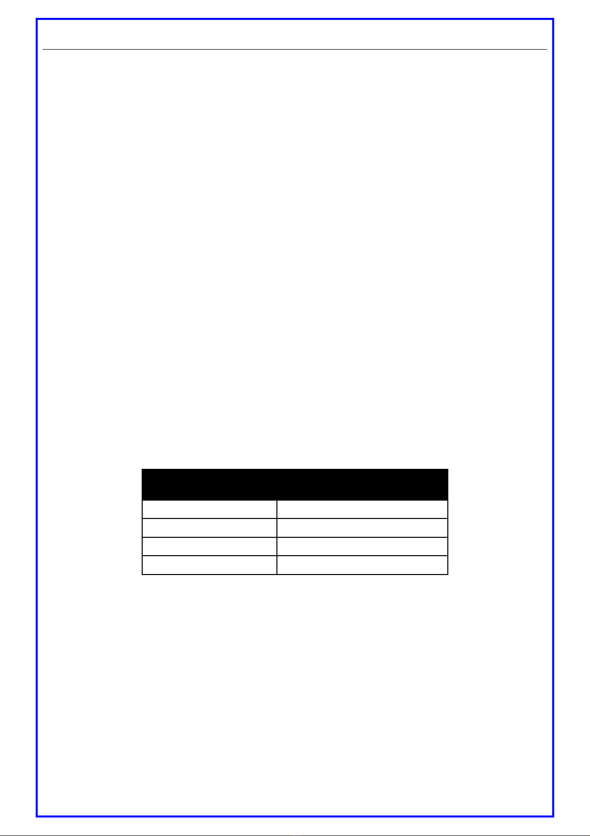
The following is a rough guide to distance and resolution:
Introducing SmartNet Router/Extender
Cat 5 Cable Length Maximum Recommended
Resolution
150m 1600 x 1200
225m 1280 x 1024
250m 1024 x 768
300m 800 x 600
Page 2
How does SmartNet X+ work?
The SmartNet X and SmartLynx receivers are high resolution components of a UXGA extender system
designed for the switching and transmitting desktop computer video and stereo audio signals over (UTP)
unshielded twisted pair category 5 (CAT 5) cabling. The transmitted signals are computer video signal, an
RGBHV (Red, Green, Blue and Horizontal and Vertical Sync) analog format, and a Stereo Audio. The basic
concept behind this product is the ability to encode and decode analog signal combined with precise line
equalization and compensation.
Smart-e (UK) Ltd, Ranmore Manor, Ranmore Common, Dorking, Surrey, RH5 6SX
+44 (0) 1483 283365 Fax: +44 (0) 1483 281511, www.smart-e.co.uk

Installation and Operation - SmartNet X+
1. Preparing for installation
Start installation process by insuring that all video displays and audio devices are compatible with the
computers being used. This is accomplished by connecting the devices directly to the computer and
checking that the devices operate as desired without the SmartNet system.
Install CAT-5 wiring between desired locations. In order to minimize system operation difficulties, avoid
routing the system cables near fluorescent lights, air conditioners, or machines that may create electrical
noise.
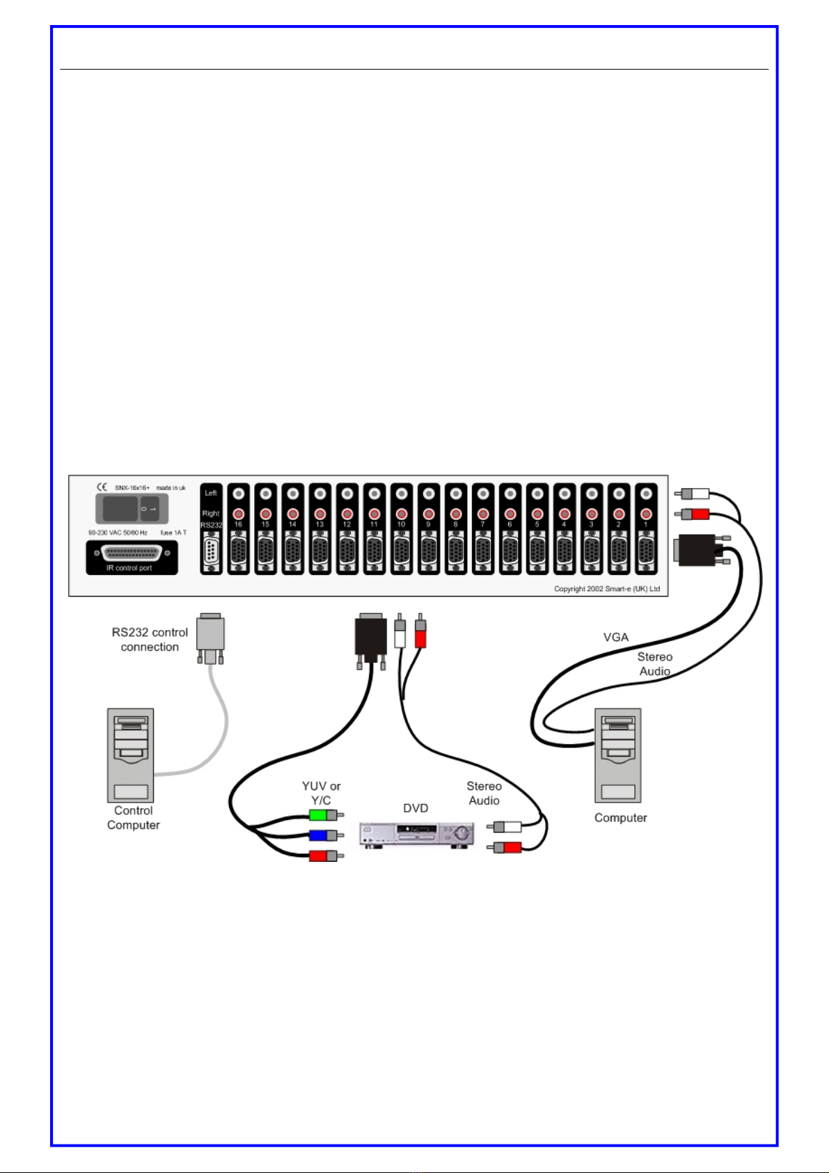
Router installation diagram
Page 3 Smart-e (UK) Ltd, Ranmore Manor, Ranmore Common, Dorking, Surrey, RH5 6SX
+44 (0) 1483 283365 Fax: +44 (0) 1483 281511, www.smart-e.co.uk
Installation and Operation - SmartNet X+
2. Connect Router to the signal source
The SmartNet X+ can be used to route and extend many video formats including VGA, CVBS, Y/C, YUV, RGBS
and RGBHV. All video connections are made to the router via high density 15 way sockets (standard VGA connec-
tions). For pin connection information please see relevant chapter.
If connecting a computer then:
2.1 Connect the output of the computer video card to the computer video input of the router using a
HD15 male to male cable.
2.2 Connect the output of the computer audio card to the audio input of the router using 3.5 mm audio
male to dual RCA male cable.
If connecting an AV source then:
2.3 Connect the output of the AV source to the video input of the router using a HD15 male to RCA,
Mini-Din or Scart cable depending on the relevant signal format (see later for cable information).
2.4 Connect the audio output of the AV source to the audio input of the router using a dual RCA male to
male cable.
3. Connecting the RS232 control port
3.1 To allow serial commands to be routed through to a display, first connect a pin to pin serial lead be-
tween the source device (PC) and the router.
3.2 Use a ‘null-modem’ cable Db9 socket (PC end) to Db9 plug (router end). Please contact nearest
Smart-e distributor or call +44 1483 283365 for serial protocol commands.
Page 4
Smart-e (UK) Ltd, Ranmore Manor, Ranmore Common, Dorking, Surrey, RH5 6SX
+44 (0) 1483 283365 Fax: +44 (0) 1483 281511, www.smart-e.co.uk
Installation and Operation - SmartNet X+
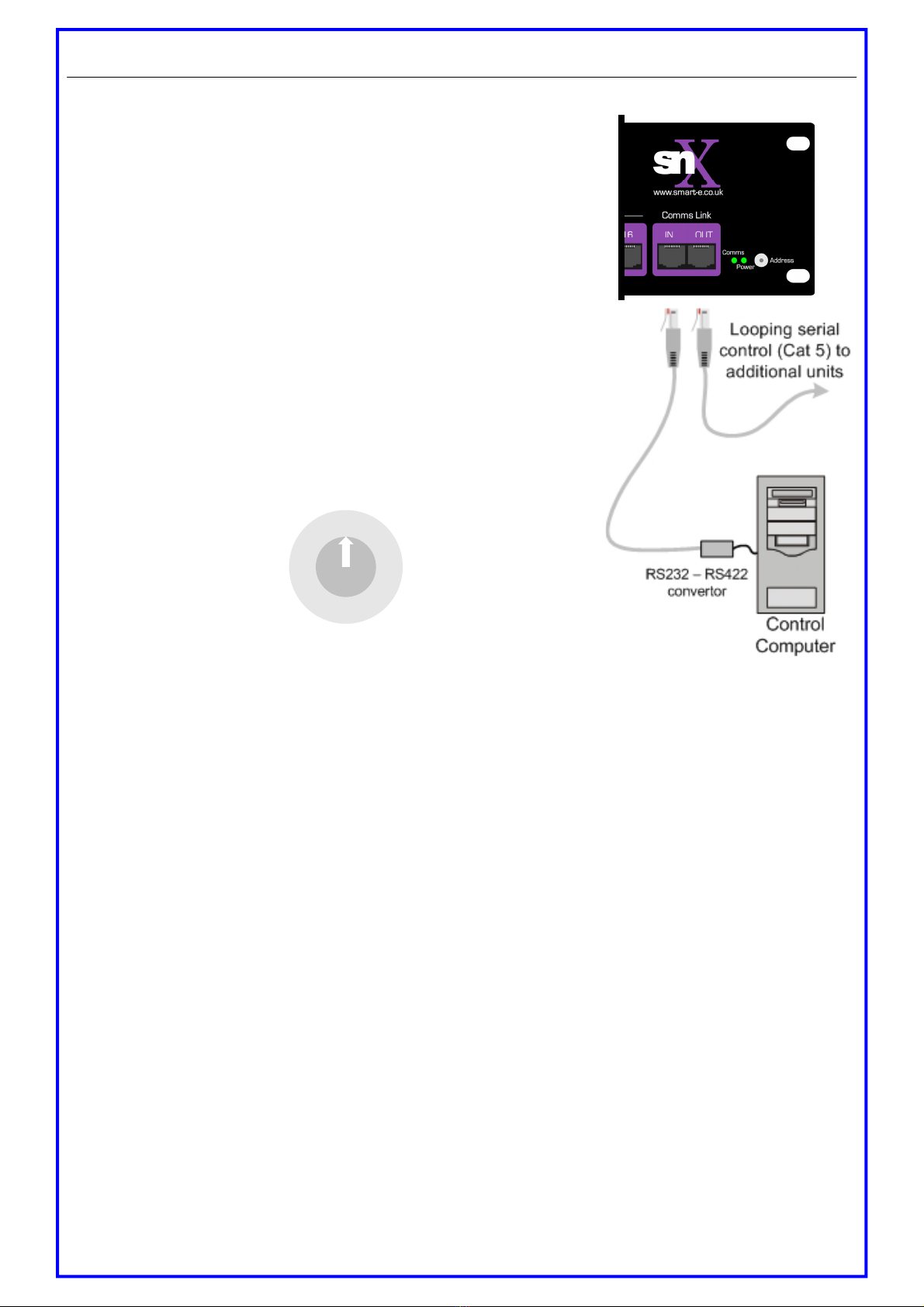
4. Controlling the SmartNet X+
4.1.Using the RS232—RS422 converter and adaptor cable provided,
connect to an available serial port on the control computer
(contact nearest Smart-e distributor or call +44 1483 283365 for
pinout information if not using supplied cable).
4.2.Then connect the RJ45 of the adaptor cable into the RJ45 socket
marked ’IN’ on the front of the SmartNet X+
4.3 Additional routers units can be linked together by looping the
control RJ45 sockets using a standard Cat 5 patch cable (not a
cross-over cable).
4.4 Each router unit must have a unique address for the serial pro-
tocol to work - this is set by adjusting the rotary HEX switch on
the rear. There are 16 positions (0-F) allowing up to 16 units to
be linked together.
5. System Power up
5.1.Turn the system on by plugging in the power adapter to the SmartNet X+, if not already connected.
5.2. Power up the source devices.
5.3.Observe both transmitter and receiver power LED are ON, and computer is fully boot-up.
5.4.Observe monitors at transmitter and receiver end displaying the same data.
Using equalization adjustment (EQ) on the back of the receiver unit adjust the image to best quality (see Re-
ceiver options). This adjustment equalizes for various cable length.
6. Preparing and connecting System CAT-5 cable
The SmartNet X+ utilizes category 5 (CAT 5), unshielded twisted pair (UTP) cable to transport signal between
transmitter and receiver.
CAT 5 cable is more desirable than coaxial cable due to its low cost and ease of installation. This cable is used for
LAN applications and is found in abundance, already installed, in many buildings . The category 5 is a standard
which establishes minimum requirements for telecommunications cabling within a commercial building. The stan-
dard covers various aspects of wiring including telecommunications outlets.
Following is the wiring standard for terminating CAT 5 cable using RJ 45 connector:
Page 5
012
3
4
5
6
7
8
9
A
B
C
D
EF
Smart-e (UK) Ltd, Ranmore Manor, Ranmore Common, Dorking, Surrey, RH5 6SX
+44 (0) 1483 283365 Fax: +44 (0) 1483 281511, www.smart-e.co.uk

Pair 1 Pins 1 & 2
Pair 2 Pins 3 & 6
Pair 3 Pins 4 & 5
Pair 4 Pins 7 & 8
Connectors: RJ-45
Capacitance: 14 pf/ft (46.2 pf/m)
Conductor Gauge: 24 AWG
Impedance: 100 +/- 15 ohms
4 - Pair
7. Connecting the IR blaster (optional)
7.1 Using the IR Blaster control cable plug one end into the IR control port on the rear of the SmartNEt X
router whilst connecting the other end to the 1U Blaster box.
7.2 Then plug the IR emitter LED into the relevant 3.5mm jack socket on the front of the Blaster box,
making sure that the port number corresponds to the video input number on the router. See diagram be
low showing IR output 6 corresponding to the video input 6.
Installation and Operation - SmartNet X+
Page 6
Smart-e (UK) Ltd, Ranmore Manor, Ranmore Common, Dorking, Surrey, RH5 6SX
+44 (0) 1483 283365 Fax: +44 (0) 1483 281511, www.smart-e.co.uk

Receiver Options
SmartLynx Receiver Options:
There are two different SmartLynx receivers available for the SmartNet X+ router range, please check the model
numbers below and the relevant page reference.
SLX-RX100
UXGA, RGsB, YUV, Y/C, CVBS and Stereo Audio
For instructions on installation of the SLX-RX100 view page 8
SLX-RX200
As SLX-RX100 but with allowing RGBS, dual screen output, Infra-Red passthrough
and RS232 control option
For instructions on installation of the SLX-RX200 view page 12
SLX-RX111
As SLX-RX100 but with allowing RGBS, Infra-Red passthrough and RS232 control
option with numerous connector types
For instructions on installation of the SLX-RX200 view page 17
Page 7 Smart-e (UK) Ltd, Ranmore Manor, Ranmore Common, Dorking, Surrey, RH5 6SX
+44 (0) 1483 283365 Fax: +44 (0) 1483 281511, www.smart-e.co.uk

Installation and Operation - SLX-RX100
SLX-RX100
The SLX-RX100 allows for the reception of UXGA,RGsB,
YUV, Y/C, CVBS and stereo audio, when broadcasted along
a single Cat5 UTP cable from a SmartNet transmitter.
The unit then distributes the received signal to a display via
a HD15 connection and to speakers via a 3.5mm mini jack.
Page 8
Smart-e (UK) Ltd, Ranmore Manor, Ranmore Common, Dorking, Surrey, RH5 6SX
+44 (0) 1483 283365 Fax: +44 (0) 1483 281511, www.smart-e.co.uk
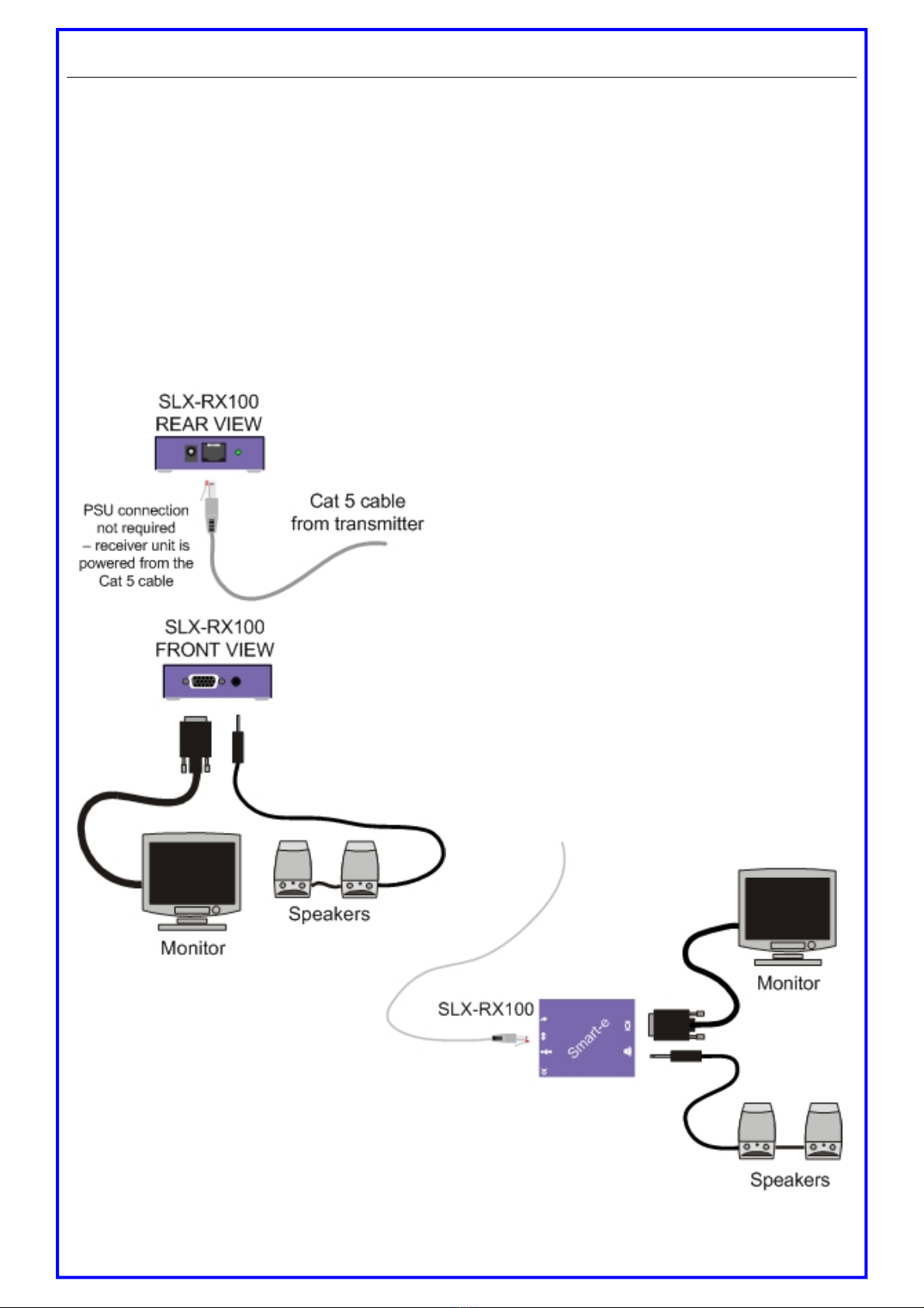
1. Connecting SLX-RX100 to the display device
1.1 Making sure that the Cat 5 cable is connected to one of the SmartNet X+ transmitter outputs,
connect the cable to the RJ45 socket on the receiver unit.
1.2 If the cable connection is correct the power LED on the front of the receiver should illuminate
(power is sent up the Cat 5 cable).
1.3 Connect the speakers or audio input on the display to the audio output on the receiver, using a
3.5mm jack plug.
1.4 Connect the display to the video output on the receiver using high quality multi-coaxial cable.
Installation and Operation - SLX-RX100
Page 9
SLX-RX100
TOP VIEW
Smart-e (UK) Ltd, Ranmore Manor, Ranmore Common, Dorking, Surrey, RH5 6SX
+44 (0) 1483 283365 Fax: +44 (0) 1483 281511, www.smart-e.co.uk
Installation and Operation - SLX-RX100 Version 1.0
Page 10
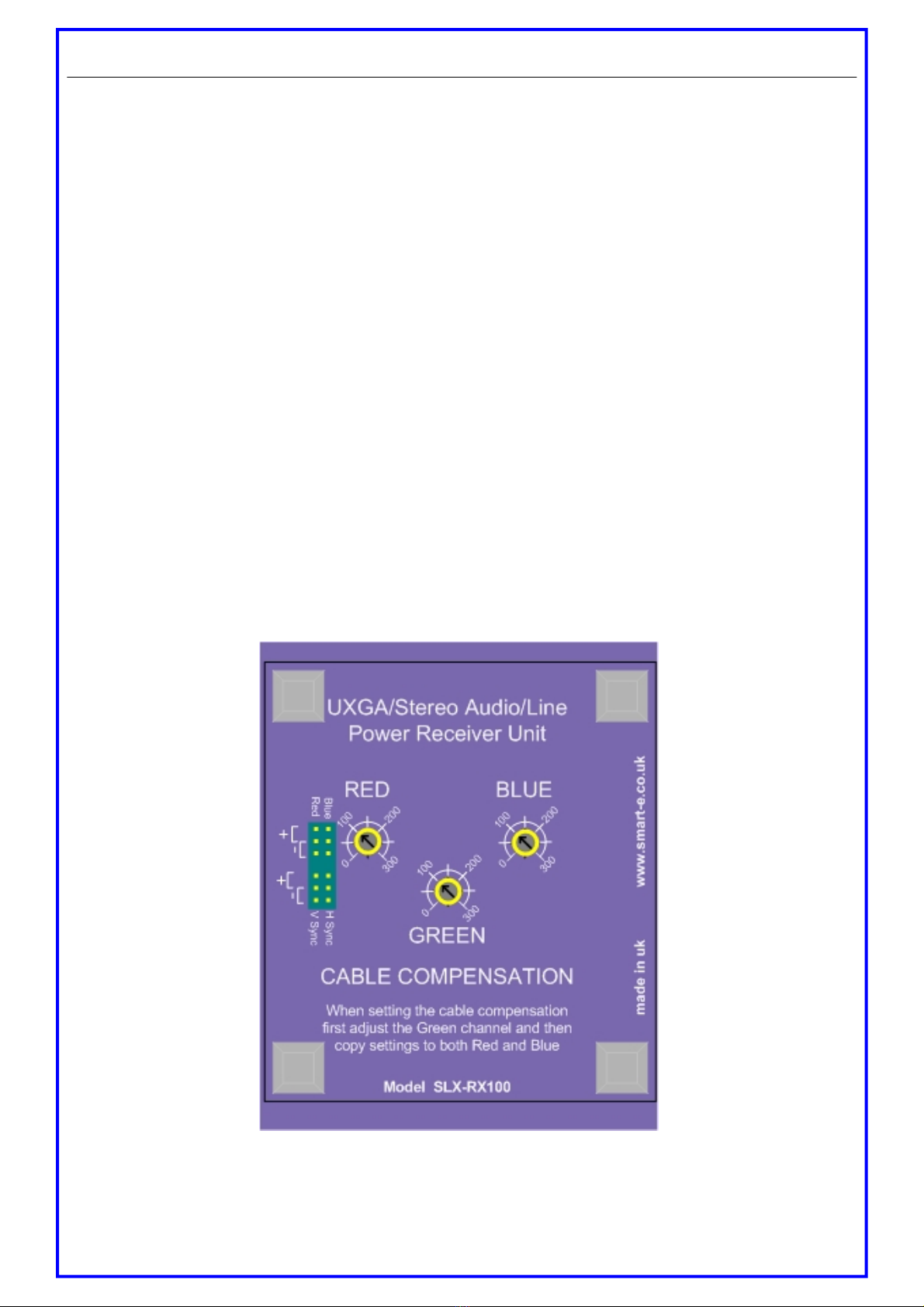
2. Setting the cable length dials
The receiver unit is preset for approximately 100m which is sufficiently accurate for most applications (if on a
cable run of < 50m adjust the dials anticlockwise to prevent sync disturbance). However, if the image does not
look sharp enough then follow the instructions below:
2.1 Load an application you intend to use that requires a high screen resolution (such as a Windows
or word processor program).
2.2 If the video is under-compensated, you will notice a black smearing on the right-hand edge of
large horizontal objects such as title bars. The degradation becomes more noticeable as length
increases.
2.3 Look at a point on the monitor where the smearing is evident. Now rotate the Green ‘EQ’ dial
clockwise until the smearing disappears and the edge becomes very bright and too sharp. At this
point and beyond the video is over-compensated (note that over-compensation of the Red chan
nel can cause sync disruption which can cause certain displays not to display any image).
2.4 Rotate the ‘EQ’ dial back slightly until you reach a point where the edge looks as it should be (no
smearing or over sharpness). The compensation is now adjusted correctly for the length of the
interconnection cable being used.
2.5 Repeat this for the other colour dials.
Please note that for all practical purposes cable equalisation cannot be exact – the remote image will never be
quite as sharp as the original.
Smart-e (UK) Ltd, Ranmore Manor, Ranmore Common, Dorking, Surrey, RH5 6SX
+44 (0) 1483 283365 Fax: +44 (0) 1483 281511, www.smart-e.co.uk

3. Sync Processing & Polarity
Sync Processing
For VGA applications the Transmitter adds the Horizontal and Vertical sync pulses to the Blue and Red channels.
Since the unit has been designed for use with other types of video the Receiver provides the ability to both pass
the Red and Blue channels transparently or process them to remove the Sync Pulses. The Green channel is al-
ways transparent.
3.1 To pass video transparently for the Red and Blue channels the jumpers must be set in the +po
sition.
3.2 To process the video and remove the sync pulses the jumpers must be set in the - position
In the example opposite the Blue channel is set to remove sync pulses and the Red
channel to pass the video transparently.
3.3 For composite video use the Green channel
3.4 For Y/C applications set the Red link to be transparent and use the Green channel for luminance
and the Red channel for Chrominance.
3.5 For YUV applications set both the Red and Blue links to transparent and use all three channels.
When switching between different video formats the SLX-RX100 can be used for VGA and compos-
ite video OR by setting the links for transparent paths the SLX-RX100 can be used for Composite
video, Y/C and YUV.
4. Sync Polarity
Using the Sync Polarity section of the jumper pins it is possible to set the polarity of the Horizontal and Vertical
Sync pulses.
4.1 To make the sync pulses positive going the jumpers should be set in the + position.
4.2 To make the sync pulses negative going the jumpers must be set in the – position.
In the example opposite the Horizontal Sync ( Sync) is positive going and the Vertical
sync (V Sync) is negative going
Installation and Operation - SLX-RX100 Version 1.0
Page 11
Smart-e (UK) Ltd, Ranmore Manor, Ranmore Common, Dorking, Surrey, RH5 6SX
+44 (0) 1483 283365 Fax: +44 (0) 1483 281511, www.smart-e.co.uk
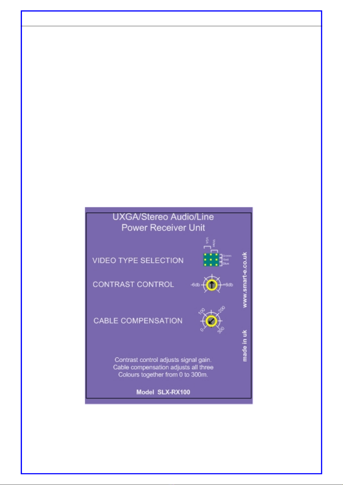
Installation and Operation - SLX-RX100 Version 4.0
5. Setting the cable length dials
The receiver unit is preset for approximately 50m which is sufficiently accurate for most applications. However
if the image does not look sharp enough then follow the instructions below:
5.1 Whilst looking at an image on the display, preferably a long horizontal bar, adjust the CABLE
COMPENSATION dial.
5.2 Looking at the right-hand edge of the bar you will see the image change. A highlighting bright
edge means over compensation whilst a blurred dark edge means under compensation.
5.3 Adjust the dial until both effects are neutralized.
The Contrast control dial is factory per-set and usually needs no adjustment.
Smart-e (UK) Ltd, Ranmore Manor, Ranmore Common, Dorking, Surrey, RH5 6SX
+44 (0) 1483 283365 Fax: +44 (0) 1483 281511, www.smart-e.co.uk Page 12

6. Sync Processing
For VGA applications the Transmitter adds the Horizontal and Vertical sync pulses to the Blue and Red channels.
Since the unit has been designed for use with other types of video the Receiver provides the ability to both pass
the Red and Blue channels transparently or process them to remove the Sync Pulses.
6.1 To pass video transparently the jumpers must be set in the Video position.
6.2 To process the video and remove the sync pulses the jumpers must be set in the
VGA position
In the example below the Blue and Green channels are set to remove sync pulses and the Red channel to pass
the video transparently.
Installation and Operation-SLX-RX100 Version 4.0
Page 13 Smart-e (UK) Ltd, Ranmore Manor, Ranmore Common, Dorking, Surrey, RH5 6SX
+44 (0) 1483 283365 Fax: +44 (0) 1483 281511, www.smart-e.co.uk
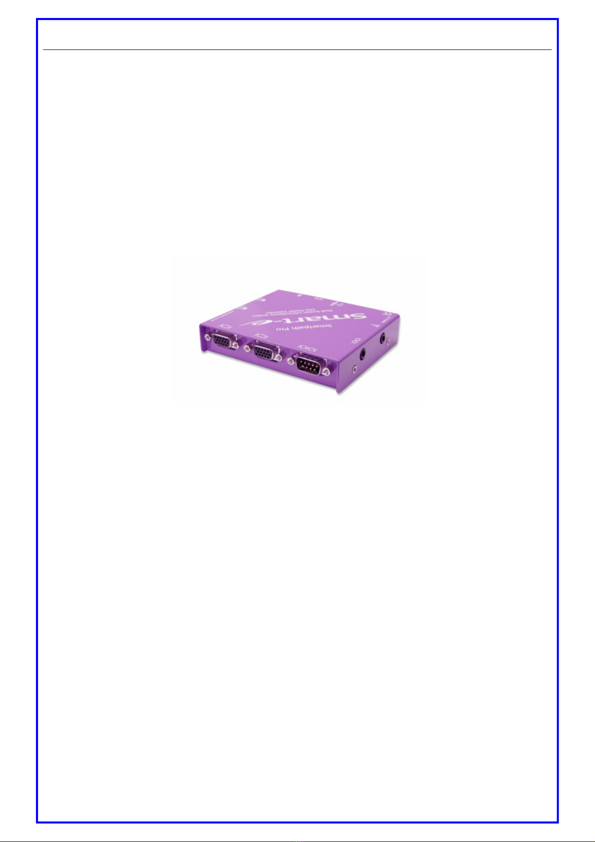
Receiver Options
The SLX-RX200 allows for the reception of UXGA, RGsB,
YUV, Y/C, CVBS and stereo audio, when broadcasted along
a single Cat5 UTP cable from a SmartNet transmitter.
The signal is received along the Cat5 from the transmitter
and then distributed to the display via a HD15 connection
and to speakers via a 3.5 mm mini jack.
The SLX-RX200 allows Infra-Red passthrough and RS232
control option.
SLX-RX200
Page 14
Smart-e (UK) Ltd, Ranmore Manor, Ranmore Common, Dorking, Surrey, RH5 6SX
+44 (0) 1483 283365 Fax: +44 (0) 1483 281511, www.smart-e.co.uk
Page 8
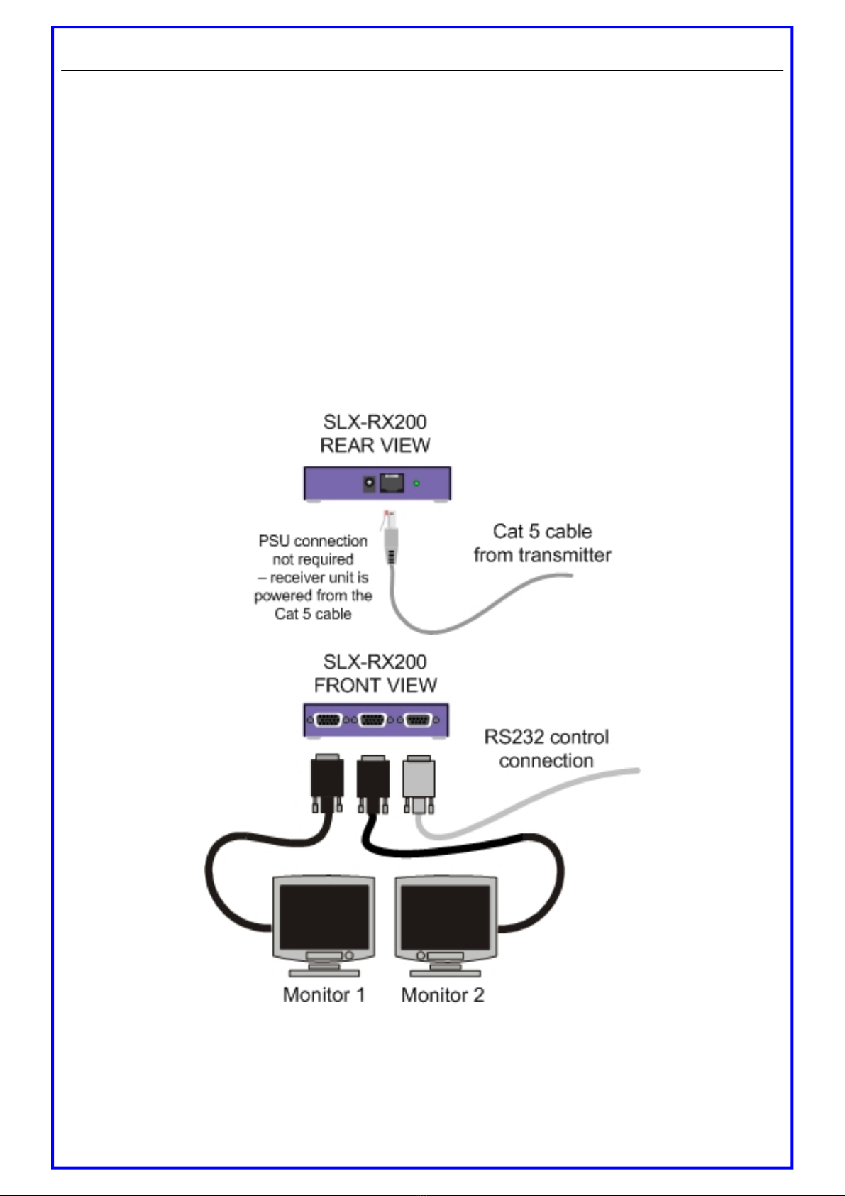
Installation and Operation - SLX-RX200
1. Connecting SLX-RX200 to the display device
1.1 Making sure that the Cat 5 cable is connected to one of the SmartNet X+ transmitter outputs,
connect the cable to the RJ45 socket on the receiver unit.
1.2 If the cable connection is correct the power LED on the front of the receiver should illuminate
(power is sent up the Cat 5 cable).
1.3 Connect each display to one of the video output on the receiver using high quality multi-coaxial
cable
1.4 If RS232 control is required then connect to the display via the dB9 socket on the receiver using
a null-modem cable (pin to pin).
Page 15
Smart-e (UK) Ltd, Ranmore Manor, Ranmore Common, Dorking, Surrey, RH5 6SX
+44 (0) 1483 283365 Fax: +44 (0) 1483 281511, www.smart-e.co.uk

Installation and Operation - SLX-RX200
2. Connecting SLX-RX200 to audio and Infra-Red control
2.1 Connect the speakers or audio input on the display to the audio output on the receiver, using a
3.5mm jack plug.
2.2 If using the receiver to transmit Infra-Red signals back down the cable to the transmitter unit
then connect an ‘eye’ to the lower jack position as shown in the diagram below.
2.3 If using the receiver to transmit Infra-Red signals up to the display from the transmitter unit then
connect an ‘IR LED’ to the adjacent jack socket.
2.4 If using RS232 signals beyond 100m of Cat 5 than a local PSU might be needed
Please note: connecting the IR ‘eye’ will prevent the return RS232 path from the display
Page 16
Smart-e (UK) Ltd, Ranmore Manor, Ranmore Common, Dorking, Surrey, RH5 6SX
+44 (0) 1483 283365 Fax: +44 (0) 1483 281511, www.smart-e.co.uk

Installation and Operation - SLX-RX200
Page 17
2. Setting the cable length dials
The receiver unit is preset for approximately 100m which is sufficiently accurate for most applications (if on a
cable run of < 50m adjust the dials anticlockwise to prevent sync disturbance). However, if the image does not
look sharp enough then follow the instructions below:
2.1 Load an application you intend to use that requires a high screen resolution (such as a Windows
or word processor program).
2.2 If the video is under-compensated, you will notice a black smearing on the right-hand edge of
large horizontal objects such as title bars. The degradation becomes more noticeable as length
increases.
2.3 Look at a point on the monitor where the smearing is evident. Now rotate the Green ‘EQ’ dial
clockwise until the smearing disappears and the edge becomes very bright and too sharp. At this
point and beyond the video is over-compensated (note that over-compensation of the Red chan
nel can cause sync disruption which can cause certain displays not to display any image).
2.4 Rotate the ‘EQ’ dial back slightly until you reach a point where the edge looks as it should be (no
smearing or over sharpness). The compensation is now adjusted correctly for the length of the
interconnection cable being used.
2.5 Repeat this for the other colour dials.
Please note that for all practical purposes cable equalisation cannot be exact – the remote image will never be
quite as sharp as the original.
Smart-e (UK) Ltd, Ranmore Manor, Ranmore Common, Dorking, Surrey, RH5 6SX
+44 (0) 1483 283365 Fax: +44 (0) 1483 281511, www.smart-e.co.uk
Table of contents
Other Smarte Extender manuals

Smarte
Smarte 4K-800 User manual

Smarte
Smarte SNX-8x8 X+ User manual

Smarte
Smarte SLX-211 User manual

Smarte
Smarte SDS-1002 User manual

Smarte
Smarte SmartLynx-X+ SLX-212/D User manual

Smarte
Smarte SDS-901 User manual

Smarte
Smarte SmartLynx SLX-800 User manual

Smarte
Smarte 4K-710 User manual

Smarte
Smarte SLX-111 User manual

Smarte
Smarte 4K-5W155 User manual


Popular Extender manuals by other brands


T.I.P.
T.I.P. HWW G-1000 Plus Translation of original operating instructions

Fisher-Price
Fisher-Price Stow ‘n Go Booster Seat manual

Wyrestorm
Wyrestorm EX-35-H2-ARC quick start guide

Patton
Patton CopperLink 1214E quick start guide

Extron electronics
Extron electronics eLink 100 Setup guide

Vanco
Vanco EVEXFBRK1 manual


