Smarte SLX-111 User manual

User Guide
Part No: SLX111UG
SmartLynx X+
Cat5 AV Extender
Model No:
SLX-111
The Clearer Picture

Edition 1, April 1, 2006
Copyright 2005 Smart-e (UK) Ltd.
Notice
The information contained in this document is subject to change
without notice. Smart-e makes no warranty of any kind with regard
to this material, including but not limited to, implied warranties of
merchantability and fitness for particular purpose.
Smart-e will not be liable for errors contained herein or for inciden-
tal or consequential damages in connection with the furnishing, per-
formance or use of this material.
No part of this document may be photocopied, reproduced , or
translated into another language without prior written consent from
Smart-e (UK) Ltd.

Table of Contents
Introducing SmartLynx ................................................1
What ‘s in the box .......................................................1
What is SmartLynx .......................................................2
Why is SmartLynx necessary.........................................2
How does SmartLynx work............................................2
Installation and Operation ...........................................3
Transmitter..................................................................3
Receiver ......................................................................6
Appendix ......................................................................9
Specifications...............................................................9
Troubleshooting ...........................................................10
Limited warranty statement ..........................................11
Partial Product List.......................................................bp

Introducing SmartLynx Cat5 AV Extender
What‘s in the box?
Thank you for buying the Smart-e SmartLynx Cat5 AV Extender. Depending
on the configuration of your system various quantities of the parts below
may be included in your shipment.
If any of the accessories listed below are missing please contact the Smart-e
dealer you purchased products from or contact Smart-e customer support at:
+44 1483 283365
If you ordered a SmartLynx Set
Item Description SLX-111
Transmitter
Unit One Input and one Cat5 Output
Transmitter unit with local output Yes
Receiver
Unit One Cat5 Input and Dual-screen
Output Receiver unit Yes
24V Earthed PSU 24 Volt 20 Watt earthed Power Supply Yes
Mains Cable Standard PSU Mains Cable Yes
Page 1 Smart-e (UK) Ltd, Ranmore Manor, Ranmore Common, Dorking, Surrey, RH5 6SX
+44 (0) 1483 283365 Fax: +44 (0) 1483 281511, www.smart-e.co.uk
What is SmartLynx?
The SmartLynx is a combination of transmitter and receiver devices
designed to transmit high resolution computer video and/or audio signal
over Cat5 wire. AV stands for Audio Visual and includes such signal for-
mats as Broadcast Video (TV video signal), Computer Video (VGA, SVGA,
SXGA and etc. signals) and various formats of Audio signals.
Why is SmartLynx necessary?
Sometimes AV signals need to be transmitted over distances greater than
commonly specified product limitations of 5m. In this case several choices
are available, but most are expensive and bulky, which is in some cases
simply not practical, due to space limitations in the conduits.
The SmartLynx allows the transmission of AV signals over a standard Cat5
UTP cable over distances of up to 300m. The actual distance is a function
of the signal resolution and cable quality. The following is a rough guide
to distance and resolution:
How does SmartLynx work?
The Smart-e SmartLynx is a transmitter and receiver pair designed to extend
video, stereo audio and IR/RS232 signals over (UTP) unshielded twisted pair
category 5 (Cat5) cabling. They are supplied with a UK power supply and
consist of: a transmitter with a video input (connectors vary by model), an
audio input and a Cat5 output and; a receiver with a cat5 input and corre-
sponding outputs. Certain models are also supplied with local outputs and/or
IR or RS232 connections.
The extended signals depends on the model but supported signals are UXGA,
CVBS, YUV(YPbPr), Y/C, RGsB and RGBS analog format and Stereo Audio.
The basic concept behind this product is the ability to encode and decode
analog signal combined with precise line equalization and compensation.
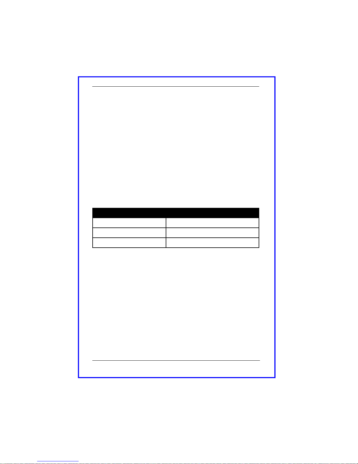
Cat5 Cable Length Maximum Recommended Resolution
100m VGA to UXGA (1600x1200)
300m SDTV
100m HDTV (720p,1080i, 1080p)
Introducing SmartLynx Cat5 AV Extender
Page 2
Smart-e (UK) Ltd, Ranmore Manor, Ranmore Common, Dorking, Surrey, RH5 6SX
+44 (0) 1483 283365 Fax: +44 (0) 1483 281511, www.smart-e.co.uk

1. Preparing for installation
Start installation process by ensuring that all video displays and audio
devices are compatible with the computers being used. This is accom-
plished by connecting the devices directly to the computer and checking
that the devices operate as desired without the SmartLynx system.
Install CAT-5 wiring between desired locations. In order to minimize
system operation difficulties, avoid routing the system cables near fluo-
rescent lights, air conditioners, or machines that may create electrical
noise.
Installation and Operation
Page 3 Smart-e (UK) Ltd, Ranmore Manor, Ranmore Common, Dorking, Surrey, RH5 6SX
+44 (0) 1483 283365 Fax: +44 (0) 1483 281511, www.smart-e.co.uk
2. Connect Transmitter to the signal source
2.1 Connect the video output of the source device to the appropri
ate input of the transmitter using the relevant cable.
2.2 Connect the audio output of the source device to the audio
input of the transmitter using the appropriate cable.
2.3 Connect the local speakers cable to the audio loop output of the
transmitter.
2.4 If using RS232 connect control cable to the minijack input as shown
in the diagram on the previous page. Using a CAB-J19F-1M
2.5 If using Infra-Red connect the SM-LED and SM-EYE to the 3.5mm
jack points as shown in the diagram on the previous page.
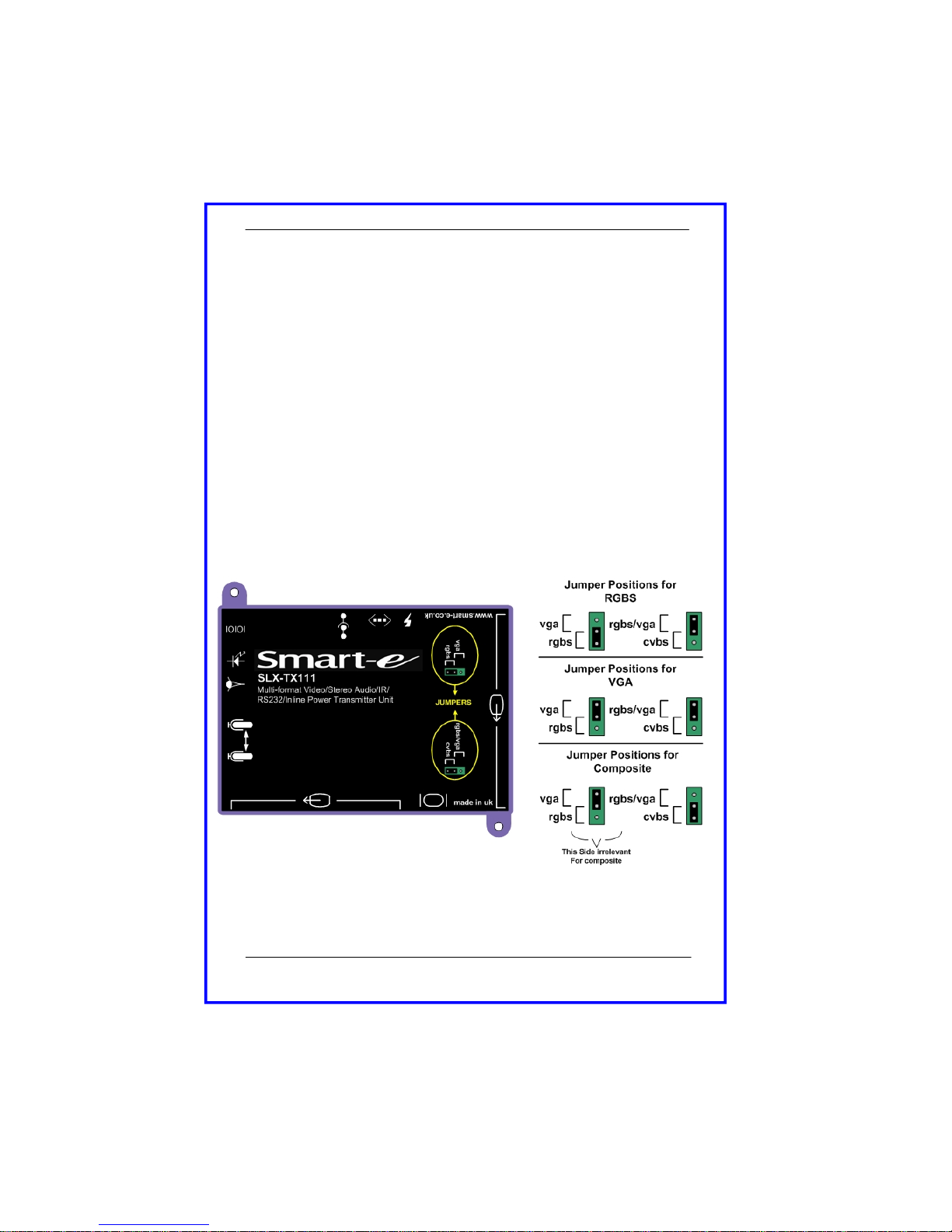
3. Setting Jumpers on Transmitter to correct position
3.1 The diagram below details how to correctly set the jumpers for the
required video type.
Installation and Operation
Page 4
Smart-e (UK) Ltd, Ranmore Manor, Ranmore Common, Dorking, Surrey, RH5 6SX
+44 (0) 1483 283365 Fax: +44 (0) 1483 281511, www.smart-e.co.uk

Installation and Operation
4.System Power up
3.1 Turn the system on by plugging in the power adapter to the
SmartLynx if they are not yet connected (See diagram oppo
site).
3.2 Power up your computer.
3.3 Observe both transmitter and receiver power LED are ON,
and source device is switched on.
5. Preparing and connecting System CAT-5 cable
The SmartLynx utilizes category 5 (CAT 5), unshielded twisted pair (UTP) cable
to transport signal between transmitter and receiver.
CAT 5 cable is more desirable than coaxial cable due to its low cost and ease of
installation. This cable is used for LAN applications and is found in abundance,
already installed, in many buildings . The category 5 is a standard which estab-
lishes minimum requirements for telecommunications cabling within a commer-
cial building. The standard covers various aspects of wiring including telecom-
munications outlets.
Following is the wiring standard for terminating CAT 5 cable using RJ 45 con-
nector:
Pair 1 Pins 1 & 2
Pair 2 Pins 3 & 6
Pair 3 Pins 4 & 5
Pair 4 Pins 7 & 8
Connectors:
RJ-45
Capacitance: 14 pf/ft (46.2 pf/m)
Conductor Gauge: 24 AWG
Impedance: 100 +/- 15 ohms
4-Pair
Page 5 Smart-e (UK) Ltd, Ranmore Manor, Ranmore Common, Dorking, Surrey, RH5 6SX
+44 (0) 1483 283365 Fax: +44 (0) 1483 281511, www.smart-e.co.uk

Installation and Operation of Receiver
Page 6
1. Connecting SLX-RX111 to the display device
1.1 Making sure that the Cat 5 cable is connected to the SLX-TX111
transmitter output, connect the cable to the RJ45 socket on
the receiver unit.
1.2 If the cable connection is correct the power LED on the front of the
receiver should illuminate (power is sent up the Cat 5 cable).
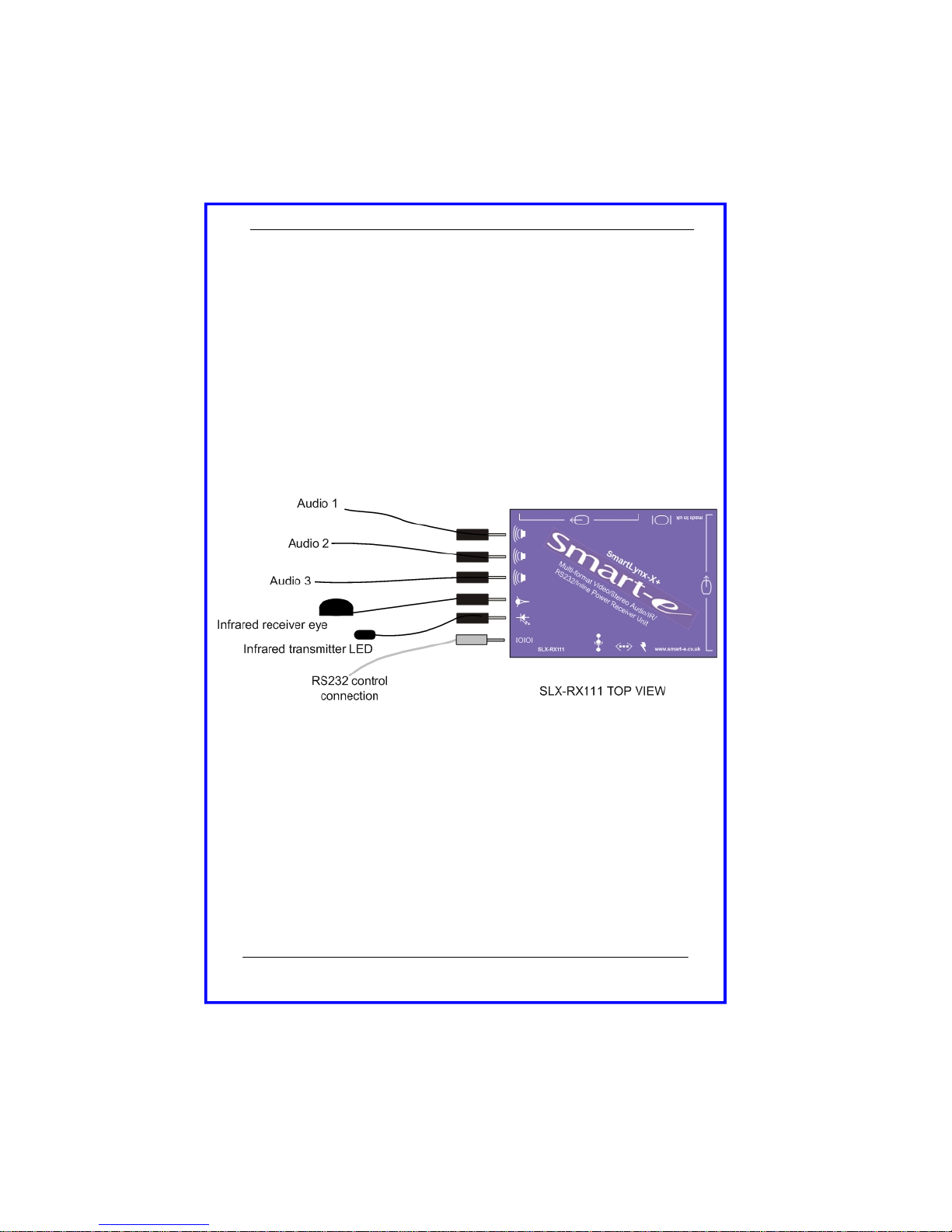
1.3 Connect the display to relevant connector on the receiver
(see diagram below) using the appropriate cable
1.4 If RS232 control is required then connect to the display via the
3.5mm minijack on the receiver using a CAB-J19-1M.
Smart-e (UK) Ltd, Ranmore Manor, Ranmore Common, Dorking, Surrey, RH5 6SX
+44 (0) 1483 283365 Fax: +44 (0) 1483 281511, www.smart-e.co.uk
Installation and Operation of Receiver
Page 7
2. Connecting SLX-RX111 to audio and Infra-Red control
2.1 Connect the speakers or audio input on the display to the audio
output on the receiver, using a 3.5mm jack plug.
2.2 If using the receiver to transmit Infra-Red signals back down the
cable to the transmitter unit then connect an ‘eye’ to the jack
position as shown in the diagram below.
2.3 If using the receiver to transmit Infra-Red signals up to the display
from the transmitter unit then connect a ‘LED’ to the jack
position as shown in the diagram below.
Please note: connecting the IR ‘eye’ will prevent the return RS232 path from the display
Smart-e (UK) Ltd, Ranmore Manor, Ranmore Common, Dorking, Surrey, RH5 6SX
+44 (0) 1483 283365 Fax: +44 (0) 1483 281511, www.smart-e.co.uk

Installation and Operation of Receiver
Page 8
3. Mounting the Receiver
The receiver unit can compensate for cable losses over a length of 20-100m, and for
mounting purposes the unit is provided with two ’mounting-hole’ points for fixing to the
wall or screen (See diagram below). Simply hold receiver in place, mark position of
holes and set screws in these locations.
NB. Always use screws with heads larger than the holes.
Smart-e (UK) Ltd, Ranmore Manor, Ranmore Common, Dorking, Surrey, RH5 6SX
+44 (0) 1483 283365 Fax: +44 (0) 1483 281511, www.smart-e.co.uk
‘MOUNTING-HOLES’
‘MOUNTING-HOLES’

Page 9
Technical Information
SLX-111
Video Input
Signal Type—Connector UXGA-HD15 / RGBS-Scart / YUV-3xRCA / YC-4pin minidin / CVBS-Scart
Bandwidth 300MHz
Impedance 75 Ohm
Audio Input
Signal Type Stereo Audio
Bandwidth 20kHz, 0dB
Impedance 10k Ohm
Connector 3.5mm mini-jack, Female
Local Audio Output
Signal Type Stereo Audio
Bandwidth 20kHz, 0dB
Impedance 100 Ohm
Connector 3.5mm mini-jack, Female
Video Output
Signal Type—Connector UXGA-HD15 / RGBS-Scart / YUV-3xRCA / YC-4pin minidin / CVBS-Scart
Bandwidth 300MHz
Impedance 75 Ohm
Audio Output
Signal Type Stereo Audio
Bandwidth 20kHz, 0dB
Impedance 100 Ohm
Connector 3 x 3.5mm mini-jacks, Female
IR Input
Signal Type 30-500kHz modulated IR
Connector 3.5mm mini-jack, Female
IR Output
Signal Type 30-500kHz modulated IR
Connector 3.5mm mini-jack, Female
RS232 Input
Signal Type RS232 up to 38.4kbaud, full duplex tx, rx
Connector 3.5mm mini-jack, Female
RS232 Output
Signal Type RS232 up to 38.4kbaud, full duplex tx, rx
Connector 3.5mm mini-jack, Female
Power 5mm x 2.1mm 24VDC 500mA
Dimensions
Transmitter 120 x 94 x 23 mm
Receiver 120 x 94 x 23 mm
Weight
Transmitter 0.2kg
Receiver 0.2kg
Smart-e (UK) Ltd, Ranmore Manor, Ranmore Common, Dorking, Surrey, RH5 6SX
+44 (0) 1483 283365 Fax: +44 (0) 1483 281511, www.smart-e.co.uk

Trouble shooting
Page 10
No video?
1) Are the green LEDs on both the transmitter and receiver units? If not check that the
24V power supply (PSU) is connected and the LED on the PSU is lit. Check the cable
compensation dials on the underside of the unit. Over compensation of the Red and
Blue channels can cause the display to misinterpret the sync pulses and not display an
image.
2) Is the video source a laptop or floating? (a floating source is one which has no earth
reference i.e. uses a double insulated PSU or a figure 8 mains cable). If so make sure
the PSU is an earthed unit when not using the PSU supplied.
3) Is the audio input level too high? The audio level should be set to line level (0dB or
700mV peak to peak) to prevent interference.
Display has problems syncing?
1) Is the audio input level too high? The audio level should be set to line level (0dB or
700mV peak to peak) to prevent interference.
Smart-e (UK) Ltd, Ranmore Manor, Ranmore Common, Dorking, Surrey, RH5 6SX
+44 (0) 1483 283365 Fax: +44 (0) 1483 281511, www.smart-e.co.uk

Limited Warranty Statement
A. Extent of limited warranty
1. Smart-e (UK) Ltd warrants to the end-user customers that Smart-e product
specified above will be free from defects in materials and workmanship for
the duration of 1 year, which duration begins on the date of purchase by
the customer. Customer is responsible for maintaining proof of date of
purchase.
2. Smart-e warranty covers only those defects which arise as a result of nor-
mal use of the product, and do not apply to any:
a. Improper or inadequate maintenance or modifications
b. Operations outside product specifications
c. Mechanical abuse and exposure to severe conditions
3. If Smart-e receives during applicable warranty period notice of defect,
Smart-e will at its discretion replace or repair defective product . If Smart-e
is unable to replace or repair defective product covered by the Smart-e
warranty within reasonable period of time Smart-e shall refund the cost of
the product.
4. Smart-e shall have no obligation to repair, replace or refund unit until cus-
tomer returns defective product to Smart-e.
5. Any replacement product could be new or like new, provided that it has
functionality at least equal to that of the product being replaced.
6. Smart-e’s limited warranty is valid in any country where the covered prod-
uct is distributed by Smart-e.
B. Limitations of warranty
TO THE EXTENT ALLOWED BY LOCAL LAW, NEITHER SMART-E NOT ITS THIRD
PARTY SUPPLIERS MAKE ANY OTHER WARRANTY OR CONDITION OF ANY KIND
WHETHER EXPRESSED OR IMPLIED , WITH RESPECT TO THE SMART-E PRODUCT ,
AND SPECIFICALLY DISCLAIM IMPLIED WARRANTIES OR CONDITIONS OF MER-
CHANTABILITY, SATISFACTORY QUALITY , AND FITNESS FOR A PARTICULAR PUR-
POSE
C. Limitations of liability
To the extent allowed by local law the remedies provided in this warranty statement
are the customers sole and exclusive remedies
TO THE EXTENT ALLOWED BY LOCAL LAW , EXCEPT FOR THE OBLIGATIONS SPE-
CIFICALLY SET FORTH IN THIS WARRANTY STATEMENT , IN NO EVENT WILL
SMART-E OR ITS THIRD PARTY SUPPLIERS BE LIABLE FOR DIRECT, INDIRECT, SPE-
CIAL, INCIDENTAL, OR CONSEQUENTIAL DAMAGES WHETHER BASED ON CON-
TRACT , TORT OR ANY OTHER LEGAL THEORY AND WHETHER ADVISED OF THE
POSSIBILITY OF SUCH DAMAGES.
D. Local law
To the extent that this warranty statement is inconsistent with local law, this war-
ranty statement shall be considered modified to be consistent with such law
Appendix
Smart-e (UK) Ltd, Ranmore Manor, Ranmore Common, Dorking, Surrey, RH5 6SX
+44 (0) 1483 283365 Fax: +44 (0) 1483 281511, www.smart-e.co.uk
Page 11


Product Range Product Code Description
SmartLynx-V Sli-100 Transmitter and Receiver Pair
SmartLynx-X SLX-400 Transmitter and Receiver Pair
SLX-100 Transmitter and Receiver Pair
SmartLynx-X+ SLX-200 Transmitter and Receiver Pair with RS232/IR
SmartCast-V SCV-TX500 One to Five Transmitter Unit
SmartCast-X SCX-TX500 One to Five Transmitter Unit
SmartCast-X+ SCX-TX550 One to Five Transmitter Unit with RS232/IR
SmartCast System TUSC-1042 & SmartCast Eurocard Rack (Up to 16)
SCV-TX500e One to Five Transmitter Eurocard
SCX-TX500e One to Five Transmitter Eurocard
SCX-TX550e One to Five Transmitter Eurocard with RS232/IR
SmartNet-V SNV-16x16 16 x 16 Distribution Matrix (Up to 256 x 256)
SmartNet-X+ SNX-16x16+ 16 x 16 Distribution Matrix (Up to 256 x 256)
SmartLynx-X+ SLX-111 Transmitter and Receiver Pair with RS232/IR
SmartNet-X+ SNX-8x8+ 8 x 8 Distribution Matrix
The Clearer Picture
Partial Product List
Smart-e (UK) Ltd, Ranmore Manor, Ranmore Common, Dorking, Surrey, RH5 6SX
+44 (0) 1483 283365 Fax: +44 (0) 1483 281511, www.smart-e.co.uk
Other manuals for SLX-111
1
Table of contents
Other Smarte Extender manuals

Smarte
Smarte SNX-16x16 X+ User manual

Smarte
Smarte SNX-8x8 X+ User manual

Smarte
Smarte 4K-800 User manual

Smarte
Smarte SDS-901 User manual

Smarte
Smarte 4K-710 User manual

Smarte
Smarte SmartLynx SLX-800 User manual

Smarte
Smarte SDS User manual

Smarte
Smarte 4K-866 User manual

Smarte
Smarte 4K-5W155 User manual

Smarte
Smarte SmartLynx-X+ SLX-212/D User manual


