Smarte 4K-866 User manual


4K-866 USER MANUAL V1.0
© 2018 Smart-e (UK) Ltd
www.smart-e.co.uk
PAGE | 2
SYMBOLS
To ensure the safe and correct use of equipment, we use a range of symbols on the equipment and in the
manuals. These symbols demonstrate the risk of physical harm or possible damage to property for the user
or others and provide guidance on standards and disposal. Symbol indications and their meanings are as
follows. Please ensure that you correctly understand these instructions before reading the manual and
operating the equipment.
WARNING. This symbol is used to indicate where important instructions are provided to
ensure the correct operation of the equipment and user safety.
To prevent fire or shock hazards, do not expose this equipment to rain or moisture. Also,
do not use this equipment’s polarized plug with an extension cord receptacle or other
outlets unless the prongs can be fully inserted. Refrain from opening the cabinet as there
are high voltage components inside. Please refer all servicing to qualified service personnel.
This symbol warns user that uninsulated voltage within the unit may have sufficient
magnitude to cause an electric shock. Therefore, it is dangerous to make any kind of contact
with any part inside this unit.
This is a WiFi product, which may cause or be susceptible to radio interference. Users may
need to take additional measures to mitigate the interference.
This is a Bluetooth product, which may cause or be susceptible to radio interference. Users
may need to take additional measures to mitigate the interference.
This is an RF Radio product, which may cause or be susceptible to radio interference. Users
may need to take additional measures to mitigate the interference.
This is an Infrared product, which may cause or be susceptible to frequency interference.
Users may need to take additional measures to mitigate the interference.
This is a product which conforms to HDbaseT specification.
This product supports full High Definition 1080p resolution.
This product supports 4K Ultra High Definition resolution.
This product supports 3D definition display.
CE certification means that the product has reached the directive safety requirements
defined by the European Union.
SGS certification means that the product has reached the quality inspection standards
proposed by the world's largest quality standards body - SGS.
This product has passed the ISO9001:2000 international quality certification
EU-wide legislation, as implemented in each Member State, requires that waste electrical
and electronic products carrying the mark (left) must be disposed of separately from
normal household waste. This includes monitors and electrical accessories, such as signal
cables or power cords. When you need to dispose of your equipment, please follow the
guidance of your local authority, or ask the agent where you purchased the product. If you
wish to dispose of used electrical and electronic products outside the European Union,
please contact your local authority so as to comply with the correct disposal method.

4K-866 USER MANUAL V1.0
© 2018 Smart-e (UK) Ltd
www.smart-e.co.uk
PAGE | 3
WARNING
In order to ensure the reliable performance of the equipment and the safety of the user, please observe the following
matters during the process of installation, use and maintenance. :
INSTALLATION
◆Please do not use this product in the following places: places with high levels of dust or soot; places with high electric
conductivity; places with corrosive or combustible gas; places exposed to high temperature, condensation, wind or
rain; places subject to the occasion of vibration or impact.
◆When installing screw or wiring, make sure that metal scraps and wire heads will not fall into the screw shaft of the
equipment, as it could cause a fire, fault, or incorrect operation.
◆When the installation work is completed, ensure there is nothing left on the ventilated vents of the equipment, including
packaging items. Blocked vents may cause a fire, fault, incorrect operation.
◆Avoid wiring and inserting cable plugs in a charged state, otherwise it is easy to cause shock, or electrical damage.
◆The installation wiring should be strong reliable and earthed.
◆For installations in areas of high interference, the installer should choose shielded cable as the high frequency signal
input or output cable, so as to improve the anti-interference ability of the system.
◆Switch off and disconnect the equipment from all power sources prior to handling, installation or wiring, otherwise it
may cause electric shock or equipment damage.
◆This product grounds to earth by the grounding wires. To avoid electric shocks, grounding wires and the earth must
be linked together. Before the connection of input or output terminals, please make sure this product is correctly
grounded.
◆All terminals and wiring should be fully sheathed or otherwise covered before connecting the equipment to a power
supply so as to avoid cause electric shock.
OPERATION AND MAINTENANCE
◆Be sure to read this manual, and fully comply with the safety recommendations, before undertaking maintenance or
operation.
◆Do not touch terminals whilst the equipment is in a powered state, or it may cause a shock, incorrect operation.
◆Switch off and disconnect the equipment from all power sources prior to cleaning or tightening terminals or
connections. These operations can lead to electric shock in a live current state.
◆Switch off and disconnect the equipment from all power sources prior to the connection or disconnection of
communication signal cables, expansion modules, or other adapters, or it may cause damage to the equipment,
incorrect operation, or lead to electric shock in a live current state.
◆Do not dismantle the equipment and avoid damaging the internal electrical components. Please refer all servicing to
qualified service personnel.
DISPOSAL
◆Be sure to dispose of the equipment in accordance with local regulations.

4K-866 USER MANUAL V1.0
© 2018 Smart-e (UK) Ltd
www.smart-e.co.uk
PAGE | 4
CONTENTS
1FUNCTION................................................................................................................................................5
2FEATURES................................................................................................................................................6
3CHASSIS PANEL DESCRIPTION ..............................................................................................................7
3.1 4K-TX866 ................................................................................................................................................ 7
3.2 4K-RX866 ................................................................................................................................................ 8
4APPLICATION DIAGRAM .........................................................................................................................9
5WHAT IS INCLUDED ..............................................................................................................................10
6ACCESSORIES........................................................................................................................................11
6.1 INFRA-RED RECEIVERS (IR RX) ..................................................................................................................... 11
6.2 INFRA-RED TRANSMITTERS (IR TX) ............................................................................................................... 12
6.3 RS232 PLUGS........................................................................................................................................... 13
6.4 POWER SUPPLY AND MAINS ADAPTER PLUG .................................................................................................. 14
7BASIC SETUP .........................................................................................................................................15
8STATUS LEDS ........................................................................................................................................16
8.1 HDBASET LINK LED...................................................................................................................................... 16
8.2 HDMI DATA LED.......................................................................................................................................... 16
8.3 HDMI HOT-PLUG DETECT LED ........................................................................................................................ 17
9HDBASET CABLING ...............................................................................................................................18
10 TECHNICAL SPECIFICATION ..............................................................................................................19
10.1 4K-TX866........................................................................................................................................... 19
10.2 4K-RX866 .......................................................................................................................................... 21

4K-866 USER MANUAL V1.0
© 2018 Smart-e (UK) Ltd
www.smart-e.co.uk
PAGE | 5
1FUNCTION
The 4K-866 is a 100m HDBaseT extender, capable of extending all 5 signals of the 5 Play feature set. These
are:
➢UHD Video
➢Audio
➢Remote Power (PoC –Power On Cable)
➢10/100 BaseT Ethernet
➢Control Signals (including RS232 and Infra-Red)
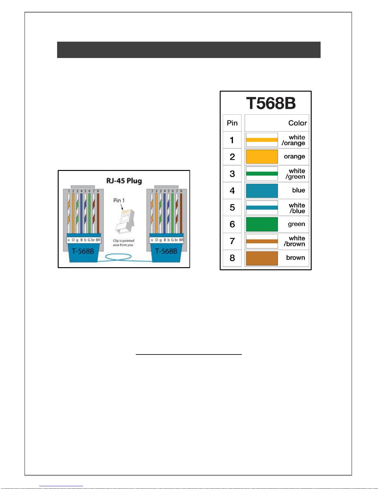
All of these signals can be transmitted between a transmitter (4K-TX866) and a receiver (4K-RX866) at a
distance of up to 100m over Cat5e-8 cabling.
The 4K-866 can extend resolutions up to 4K @30Hz 24bpp (8-bit colour depth) or 4K @24Hz 30bpp (10-bit
colour depth) over 100m of Cat5e-8 cable. This makes the 4K-866 the ideal extension solution for a Sky Q or
4K-UHD Blu-ray player. The 4K-866 is compliant with the HDMI 1.4 standard meaning it can transmit any
HDMI signal up to a total TMDS clock of 340MHz. The 4K-866 is also compliant with the HDCP 2.2 standard
making it suitable for the extension of UHD signals with copy protection such as movies or encrypted content
from satellite and cable receivers.
Within the HDBaseT protocol it is also possible to transmit surround sound up to 7.1 channels. This makes
the 4K-866 ideal for feeding your surround sound system or AV receiver. The audio through the 4K-866 is
carried embedded within the HDMI signal, to extract you can use the optical output on the rear of your screen,
commonplace in most modern screens or use an inline audio de-embedder.
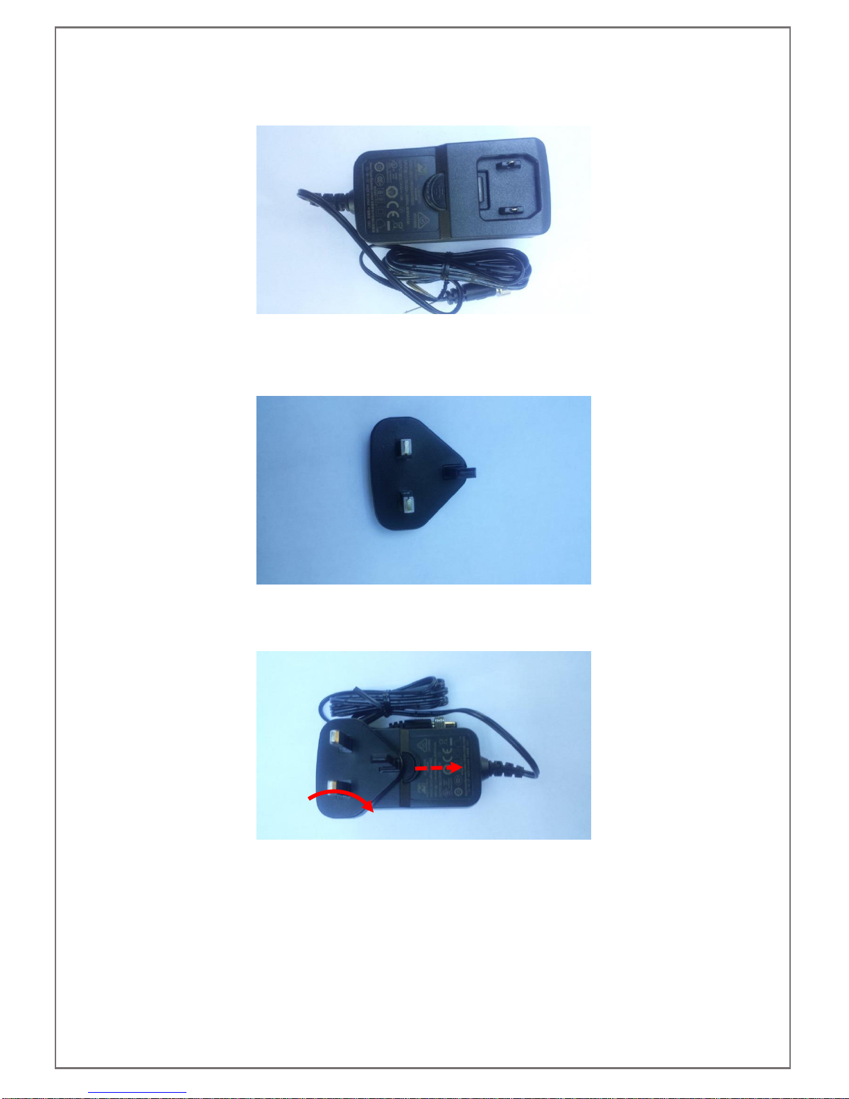
The 4K-866 requires a single 24V power supply (power supply included with purchase of a single item or pair).
Whichever end the power is supplied to, the 24V power will be sent remotely to the other unit. This enables
the user to place the power supply in the most convenient location, for example to keep unsightly cables away
from the screen location the power supply could be attached to the transmitter in your AV source cupboard
and power supplied remotely to the receiver at the screen location.
The 4K-866 also offers the ability to extend ethernet at speeds up to 100BaseT (100 Mbps) otherwise known
as Fast Ethernet. This makes it ideal for use with laptops at remote stations where wireless is not available or
to provide a wired Ethernet connection to your Smart TV providing download speeds that would not be possible
via a wireless connection. This increased speed will enable your Smart TV to take advantage of 4K streaming
utilities from apps such as BBC iPlayer, Netflix or Amazon Prime which may have struggled to maintain a 4K
stream via a wireless connection.
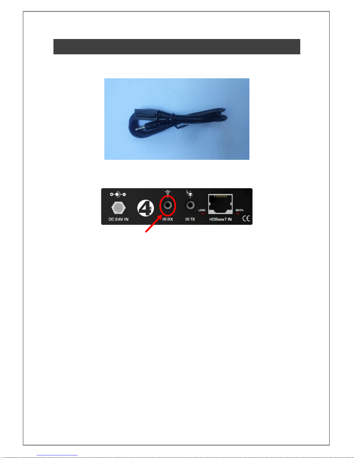
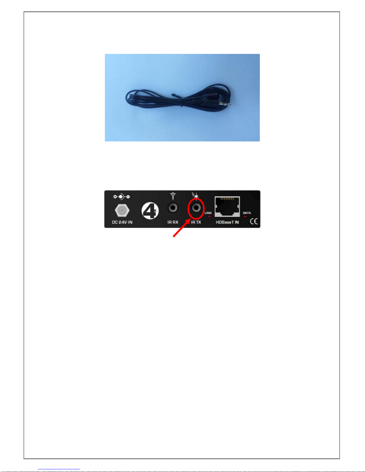
Another feature of the 4K-866 is the ability to send bi-directional infra-red signals. Each unit, TX and RX, are
supplied with an infra-red receiver and an infra-red transmitter. These devices make it possible to send infra-
red signals to and from each unit’s location. For example, with the use of a Sky Q box, the user can watch the
content on the screen and send infra-red signals back to the Sky Q box located up to 100m away with the use
of the Sky Q handset or a suitably programmed 3rd party handset.
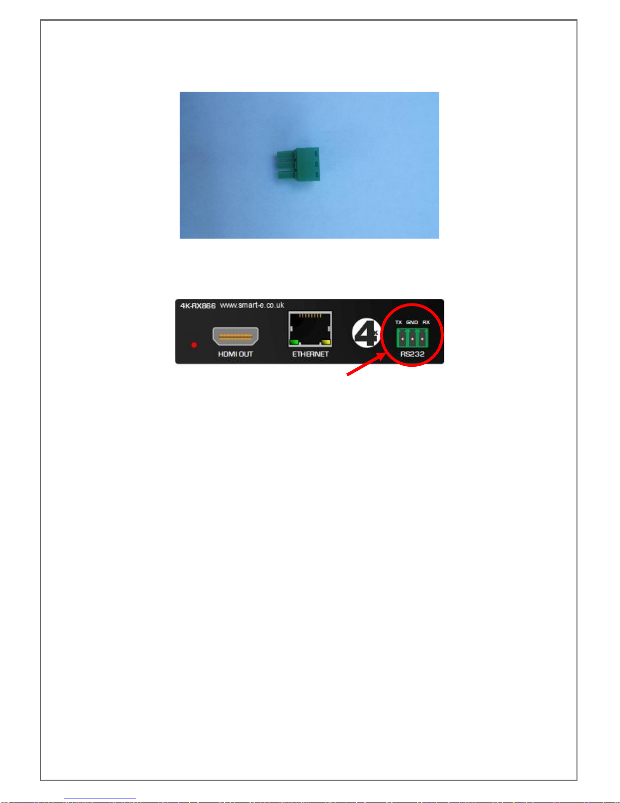
The 4K-866 can handle bi-directional RS232. With a baud rate of up to 115200, control signals can be sent
from either the transmit or receiver device and receive back the appropriate responses generated. This means
the 4K-866 can be used to integrate in to a wider control system or be used to send commands directly to a
screen or a projector from a serial control device.
Finally, the 4K-866 provides a transparent EDID path from source to sink (screen) device. EDID is the method
by which a screen tells a source what resolution, refresh rate, colour depth and many other factors it is capable
of. By presenting a transparent path the 4K-866 allows the optimal image and sound quality to pass through
the HDBaseT link.

4K-866 USER MANUAL V1.0
© 2018 Smart-e (UK) Ltd
www.smart-e.co.uk
PAGE | 6
2FEATURES
▪Small form factor –Only 25mm high
▪Utilizes easy to install and relatively inexpensive CAT 5e-8 cabling
▪Support HDMI up to 340MHz TMDS clock
▪HDCP/EDID/DCC transparent link
▪HDMI resolutions 4K, 2K & 1080p
▪HDCP 2.2 compatible
▪Full duplex RS232 passthrough
▪Bi-directional infra-red passthrough
▪100BaseT Ethernet passthrough
▪1x CAT5e U/FTP or S/FTP cable required
▪Supplies 24V remote power (PoC) to either end
▪Uses HDBaseT technology
▪Status LEDs
▪Lockable DC jack connection
▪Vented and robust housing

4K-866 USER MANUAL V1.0
© 2018 Smart-e (UK) Ltd
www.smart-e.co.uk
PAGE | 7
3CHASSIS PANEL DESCRIPTION
3.1 4K-TX866
1. 24V lockable DC jack input
2. Infra-red input port
3. Infra-red output port
4. HDBaseT link indicator LED
5. HDBaseT output port
6. HDMI data indicator LED
7. HDMI hot-plug detect indicator LED
8. HDMI input port
9. Ethernet port
10. RS232 connection

4K-866 USER MANUAL V1.0
© 2018 Smart-e (UK) Ltd
www.smart-e.co.uk
PAGE | 8
3.2 4K-RX866
1. 24V lockable DC jack input
2. Infra-red input port
3. Infra-red output port
4. HDBaseT link indicator LED
5. HDBaseT input port
6. HDMI data indicator LED
7. HDMI hot-plug detect indicator LED
8. HDMI output port
9. Ethernet port
10. RS232 connection

4K-866 USER MANUAL V1.0
© 2018 Smart-e (UK) Ltd
www.smart-e.co.uk
PAGE | 9
4APPLICATION DIAGRAM

4K-866 USER MANUAL V1.0
© 2018 Smart-e (UK) Ltd
www.smart-e.co.uk
PAGE | 10
5WHAT IS INCLUDED
4K-866
➢1x 4K-TX866
➢1x 4K-RX866
➢1x 24V power supply
➢1x Mains adapter (regional variation)
➢2x IR receivers
➢2x IR transmitters
➢2x RS232 3-pin plugs
4K-TX866
➢1x 4K-TX866
➢1x 24V power supply
➢1x Mains adapter (regional variation)
➢2x IR receivers
➢2x IR transmitters
➢2x RS232 3-pin plugs
4K-RX866
➢1x 4K-RX866
➢1x 24V power supply
➢1x Mains adapter (regional variation)
➢2x IR receivers
➢2x IR transmitters
➢2x RS232 3-pin plugs
Please ensure you have all parts listed above prior to installation, if any components are missing or
damaged please contact Smart-e support immediately.

4K-866 USER MANUAL V1.0
© 2018 Smart-e (UK) Ltd
www.smart-e.co.uk
PAGE | 11
6ACCESSORIES
6.1 INFRA-RED RECEIVERS (IR RX)
The infra-red receiver for the 866 range consists of a photo diode at one end and a 3.5mm stereo jack on the
other. The photo diode accepts infra-red signals from an infra-red emitting handset and the 3.5mm jack takes
this signal to the TX or RX866 to the 3.5mm socket as indicated below.
NOTE: Only IR RX units supplied with the 866 unit are compatible, use of other IR RX devices may result
in no infra-red functionality.

4K-866 USER MANUAL V1.0
© 2018 Smart-e (UK) Ltd
www.smart-e.co.uk
PAGE | 12
6.2 INFRA-RED TRANSMITTERS (IR TX)
The infra-red transmitter for the 866 range consists of an infra-red emitting diode at one end and a 3.5mm
stereo jack at the other. The 3.5mm stereo jacks takes infra-red signals from the 866 device and send them
to the IR emitting diode, the IR emitting diode should then be attached in close proximity of the IR receiver of
the device you wish to control. A small adhesive pad is included to attach to your device, please check with the
manufacturer of the device you wish to control where the IR receiver is located to ensure reliable functionality.
The 3.5mm jack of the IR TX should be inserted in to the 3.5mm socket as shown below.
NOTE: Only IR TX units supplied with the 866 unit are compatible, use of other IR TX devices may result
in no infra-red functionality.

4K-866 USER MANUAL V1.0
© 2018 Smart-e (UK) Ltd
www.smart-e.co.uk
PAGE | 13
6.3 RS232 PLUGS
Each 866 device is supplied with a 3-pin phoenix screw lock plug to insert in to the receptacle on the 866 as
indicated below. The pin out is indicated on the silk screen of the 866 device, you should strip back
approximately 10mm of cable and then secure by screwing in to the appropriate space of the screw lock plug.
Make sure cable is not attached to your RS232 controller whilst stripping or attaching to the terminal block.

4K-866 USER MANUAL V1.0
© 2018 Smart-e (UK) Ltd
www.smart-e.co.uk
PAGE | 14
6.4 POWER SUPPLY AND MAINS ADAPTER PLUG
Above is a picture of the 24V power supply sent with each individual TX or RX 866 unit when purchased
individually, if items are purchased as a pair (4K-866) then one unit will be sent to power both units through
PoC. Below is an example image of one of the mains plug adapters, this example is of a UK plug but the variant
supplied will depend on the region to which the 866 is supplied.
To attach the mains plug adapter to the power supply, first pull up the insertion tab on the power supply and
then rotate the mains plug adapter in to position. Once in place release the tab and the mains plug adapter will
be held in place.

4K-866 USER MANUAL V1.0
© 2018 Smart-e (UK) Ltd
www.smart-e.co.uk
PAGE | 15
7BASIC SETUP
1. Test the CATx cables to be used for HDBaseT link and if required Ethernet. This can be achieved with
a cable tester, optionally you could purchase a 4K-9000 HDBaseT tester from Smart-e which is
purpose built to test for HDBaseT installations. Ensure cables are terminated correctly and preferably
to the specification as outlined in section 9 of this manual.
2. Attach all general input and output cables to your 866 units:
➢HDMI cables
➢Ethernet cables
➢IR TX and IR RX devices
➢RS232 connections
3. Attach the screw lock output of the power supply to the DC input jack of either the TX or RX 866 unit
4. Connect the HDBaseT CATx cable between the 866 units
5. Plug the power supply in to a mains outlet
6. There is no power specific indication on the 866 units, to check functionality a number of status LEDs
are supplied on each unit, to show their meaning and how they can aid in fault locating refer to section
8 of this manual.

4K-866 USER MANUAL V1.0
© 2018 Smart-e (UK) Ltd
www.smart-e.co.uk
PAGE | 16
8STATUS LEDS
8.1 HDBASET LINK LED
A HDBaseT indicator LED is located next to the RJ45 HDBaseT connector on both the TX and RX variants of
the 866. This is the primary indication to show the CATx cable used is suitable to enable the TX and RX devices
to communicate with one another. When working this LED should be lit solid red. If not lit or blinking it means,
there is a problem with either the transmission medium (CATx cable) or with either the TX or RX unit.
If the LED is not lit it would first be advisable to check that the cabling recommendations of section 9 of this
manual have been adhered to. Test the cable using a cable tester or preferably with the use of a 4K-9000, the
units of the 4K-9000 can then be utilized, through a process of elimination, to identify if there may be a problem
with the TX or RX 866 units.
8.2 HDMI DATA LED
The HDMI data LED is located next to the HDBaseT RJ45 connector as indicated above. This LED shows the
flow of HDMI data and the type of HDMI data.
LED Status
HDMI Data
Not Illuminated
No HDMI data
Blinking
Non-HDCP HDMI data
Solidly Illuminated
HDCP HDMI data
The DATA LED will only blink or be solidly lit when a complete throughput of HDMI data is possible from the
source to the screen. If the LED is not lit firstly ensure that both the source and screen are powered on and
that the screen is set to the right output.
Ensure the source is outputting a resolution the screen is capable of displaying, this may mean taking the
source and attaching directly to the screen using a HDMI cable. Whilst performing this step it would be worth
checking both HDMI cables being used to see if they are both working.
If these tests are both completed successfully it suggests the problem lies with the TX866, RX866 or the
HDBaseT CATx cable. The easiest way to determine this would be with the use of a 4K-9000 HDBaseT tester
pair.

4K-866 USER MANUAL V1.0
© 2018 Smart-e (UK) Ltd
www.smart-e.co.uk
PAGE | 17
8.3 HDMI HOT-PLUG DETECT LED
The HDMI hot-plug detect LED is located next to the HDMI socket on both the TX and RX variants of the 866
and is located as indicated above. This LED shows that the 5V, Hot-Plug Detect mechanism of the HDMI is
working correctly. A HDMI compliant source outputs a +5V signal, this signal is detected by a HDMI compliant
screen and it responds with a Hot-Plug Detect +5V signal to tell the source a screen is attached. The 4K-866
can handle this mechanism at both the TX and RX end.
The RX866 outputs a +5V signal replicating a source, when the screen detects this signal it responds with
the Hot-Plug Detect +5V and this then illuminates the LED.
The TX866 waits to detect an incoming +5V from a source and when detected this will light the LED and
respond with the +5V Hot-Plug Detect signal, telling the source a screen is attached.
If either LED is not lit it could be because of a faulty HDMI cable, try swapping this cable or test in a known
setup to determine it’s working state.
The source and screen will need to be in at least standby mode for this mechanism to work, check both devices
are at least in standby power mode as sources and screens can often power off completely dependant on the
power management plans of the hardware.
If the above methods do not determine the source of the problem the use of the 4K-9000 would be helpful as
this can accurately determine the point where the 5V, Hot-Plug Detect mechanism is breaking down.

4K-866 USER MANUAL V1.0
© 2018 Smart-e (UK) Ltd
www.smart-e.co.uk
PAGE | 18
9HDBASET CABLING
It is advised to use T568B termination at the 4K-8x8-L and receiver termination points.
NOTE: As the 4K-8x8-L utilises power over cable (POC), if the CATx cable is incorrectly terminated there
is a danger of damaging both the 4K-8x8-L output and receiver. If you suspect an incorrectly terminated
cable may have been applied, please contact Smart-e support immediately.
HDBaseT signals can be susceptible to noise, causing image loss or snowy effects on output screens. The
best way to mitigate against these problems is by using a high quality CATx cable. Smart-e specify cable as
below.
RECOMMENDED CATx CABLE
Connectix CAT6a U/FTP Solid core cable

4K-866 USER MANUAL V1.0
© 2018 Smart-e (UK) Ltd
www.smart-e.co.uk
PAGE | 19
10 TECHNICAL SPECIFICATION
10.1 4K-TX866
Audio and Video Ports
Input Ports
1x HDMI
Output Ports
None
Serial port
Serial control interface
RS-232, 3 pin female phoenix connector
Baud rate and protocol
Baud rate: 115200, data bits: 8 bits, stop bits: 1 bit, no parity check bit
Serial control interface
structure
3 pin female phoenix interface: 1 = TX, 2 = GND, 3 = RX
Ethernet port
Ethernet Interface
RJ45 female interface with activity indicators
Ethernet Speed
Adaptive 10M/ 100M, full-duplex or half-duplex
Specifications
Mains Power to external
power supply
100VAC-240VAC, 50/60Hz, international adaptive power
Power Adapter Output
5VDC, 3A, 2.1mm centre positive 11mm barrel with locking function
Power Input Connector
2.1mmx5.5mm centre positive DC connector with locking function
Operating temperature
range
0 - +40 degrees Celsius
Storage temperature
range
-20 - +60 degrees Celsius
Relative humidity
operational or storage
20 - 90% (non-condensing)
Product weight
320g
Power consumption
4.5W (max)/0.8W (standby)
Chassis dimensions
100(l)x100(w)x25(d)mm
Mean time between
failures
30,000 hours
Quality guarantee
3-year return to base warranty
HDMI port specification
Protocols
HDMI 1.4b, HDCP 2.2 and DVI 1.0
Interface
1x Independent HDMI (Type-A) Female
Gain
0 dB
Pixel Bandwidth
340MHz full digital
Interface Bandwidth
3.4Gbps, Full digital (a total of 10.2Gbps, each colour is 3.4Gbps)
Maximum Resolution
PC: 1600x1200 @60Hz 48-bit
HDPC: 1920x1200p @60Hz 36-bit
HDTV: 3840x2160 @30Hz 4:2:0
Clock Jitter
<0.15T bit
Rise Time
<0.3T bit (20-80%)

4K-866 USER MANUAL V1.0
© 2018 Smart-e (UK) Ltd
www.smart-e.co.uk
PAGE | 20
Fall Time
<0.3T bit (20-80%)
Maximum Transmission
Delay
5ns (+/- 1ns)
Signal Strength
T.M.D.S +/- 0.4V p-p
Minimum/Maximum
Level
T.M.D.S 2.9V/3.3V
Impedance
50Ω
EDID
Pass-through
Maximum DC Offset
error
15mV
Maximum Input cable
length
15 meters (always use high quality cable)
Maximum Output cable
length
N/A
HDBaseT port specification
Protocols
HDBaseT
Input Ports
None
Output Ports
1x RJ45 female
Gain
0 dB
Pixel Bandwidth
340MHz Full Digital
Interface Bandwidth
3.40Gbps, Full digital (a total of 10.2Gbps, each colour is 3.40Gbps)
Maximum Resolution
PC: 1600x1200 @ 60Hz 48-bit
HDPC: 1920x1200p @ 60Hz 36-bit
HDTV: 3840x2160 @ 30Hz 4:2:0
Clock Jitter
<0.15T bit
Rise Time
<0.3T bit (20%~80%)
Fall Time
<0.3T bit (20%~80%)
Signal Type
High speed differential signal defined in HDBaseT protocol
PoC
24V
EDID
Pass-through
RS232 Serial Control Signal
Pass-through
Infrared Control Signal
Pass-through
Maximum DC offset error
15mV
Maximum Input Cable
N/A
Maximum Output Cable
≤100-meters
(CAT 5e –7a U/UTP –S/FTP)
This manual suits for next models
2
Table of contents
Other Smarte Extender manuals

Smarte
Smarte SNX-16x16 X+ User manual

Smarte
Smarte 4K-710 User manual

Smarte
Smarte SmartLynx SLX-800 User manual

Smarte
Smarte 4K-5W155 User manual

Smarte
Smarte SmartLynx-X+ SLX-212/D User manual

Smarte
Smarte SNX-8x8 X+ User manual

Smarte
Smarte 4K-800 User manual

Smarte
Smarte SDS-1002 User manual

Smarte
Smarte SLX-111 User manual

Smarte
Smarte SDS User manual