Smartec CLD 130 User manual

BA 001C/07/en/02.97
No. 50040314 smartec
CLD 130
Conductivity
Measurement
Operating Instructions
Quality made by
Endress+Hauser
ISO 9001

Table of contents
1. General .......................................................... 2–3
1.1 Unpacking............................................................ 2
1.2 Application............................................................ 2
1.3 Ordercode ........................................................... 3
2. Measuring system . . . . . . . . . . . . . . . . . . . . . . . . . . . . . . . . . . . . . . . . . . . . . . . . . 4 – 5
2.1 Measuring principle. . . . . . . . . . . . . . . . . . . . . . . . . . . . . . . . . . . . . . . . . . . . . . . . . . . . . 4
2.2 Sensor............................................................... 4
2.3 Measuring transmitter . . . . . . . . . . . . . . . . . . . . . . . . . . . . . . . . . . . . . . . . . . . . . . . . . . . 4
2.4 Designs.............................................................. 5
3. Installation . . . . . . . . . . . . . . . . . . . . . . . . . . . . . . . . . . . . . . . . . . . . . . . . . . . . . . . 6 – 9
3.1 Sensor with integrated transmitter. . . . . . . . . . . . . . . . . . . . . . . . . . . . . . . . . . . . . . . . . . 6
3.2 Sensor with separate transmitter. . . . . . . . . . . . . . . . . . . . . . . . . . . . . . . . . . . . . . . . . . . 7
3.3 Sensor with integrated transmitter. . . . . . . . . . . . . . . . . . . . . . . . . . . . . . . . . . . . . . . . . . 8
3.4 Immersion sensor with separate transmitter. . . . . . . . . . . . . . . . . . . . . . . . . . . . . . . . . . 8
3.5 Separate transmitter . . . . . . . . . . . . . . . . . . . . . . . . . . . . . . . . . . . . . . . . . . . . . . . . . . . . 9
4. Electrical connection . . . . . . . . . . . . . . . . . . . . . . . . . . . . . . . . . . . . . . . . . . . . . 10 – 11
4.1 Connection principles . . . . . . . . . . . . . . . . . . . . . . . . . . . . . . . . . . . . . . . . . . . . . . . . . . 10
4.2 Sensor with integrated transmitter. . . . . . . . . . . . . . . . . . . . . . . . . . . . . . . . . . . . . . . . . 10
4.3 Sensor with separate transmitter. . . . . . . . . . . . . . . . . . . . . . . . . . . . . . . . . . . . . . . . . . 11
5. Start-up ............................................................ 12
5.1 Power-up............................................................ 12
5.2 Instrument settings . . . . . . . . . . . . . . . . . . . . . . . . . . . . . . . . . . . . . . . . . . . . . . . . . . . . 12
5.3 ATCsetting .......................................................... 12
5.4 Measuring mode . . . . . . . . . . . . . . . . . . . . . . . . . . . . . . . . . . . . . . . . . . . . . . . . . . . . . . 12
6. Operation....................................................... 13–16
6.1 Measuringrangechange-over........................................... 13
6.2 ATC adjustment (automatical temperature compensation) . . . . . . . . . . . . . . . . . . . . . 14
6.3 Signal output change-over . . . . . . . . . . . . . . . . . . . . . . . . . . . . . . . . . . . . . . . . . . . . . . 15
6.4 Signal output assignment . . . . . . . . . . . . . . . . . . . . . . . . . . . . . . . . . . . . . . . . . . . . . . . 15
6.5 Remote switching of current output . . . . . . . . . . . . . . . . . . . . . . . . . . . . . . . . . . . . . . . 16
7. Maintenance and troubleshooting. . . . . . . . . . . . . . . . . . . . . . . . . . . . . . . . . . 17 – 18
7.1 Maintenance ......................................................... 17
7.2 Troubleshooting. . . . . . . . . . . . . . . . . . . . . . . . . . . . . . . . . . . . . . . . . . . . . . . . . . . . . . . 17
7.3 Instrument function test . . . . . . . . . . . . . . . . . . . . . . . . . . . . . . . . . . . . . . . . . . . . . . . . . 18
8. Technical data. . . . . . . . . . . . . . . . . . . . . . . . . . . . . . . . . . . . . . . . . . . . . . . . . . . . . . . 19
BE1LD130.CHP
Smartec CLD 130 Table of contents
1
1. General
1.1 Unpacking
•Inspect for any damaged packaging!
The post office or forwarding agent must be
informed of any damage.
Damaged packaging material must be
retained until the matter has been settled.
•Verify that the contents are undamaged!
Inform the post office or forwarding agent as
well as the supplier of any damage.
•Check if the delivery is complete and
agrees with the shipping documents as well
as your order:
•Delivered quantity
•Instrument type and version
•Accessories
•Operating instruction(s)
•Instrument identification card(s)
If you have any questions, consult your
supplier or the Endress+Hauser sales center
in your area (see back page of these
operating instructions for addresses).
1.2 Application
Use: Conductivity measurement
Measuring
principle: inductive
Application area: in liquids
Measuring range: medium to high
conductivities
Special features: sterilizable
no influence of
contamination on
measurement, resistant to
chemicals, fully
encapsulated
Applications: food industry,
chemical industry,
electroplating
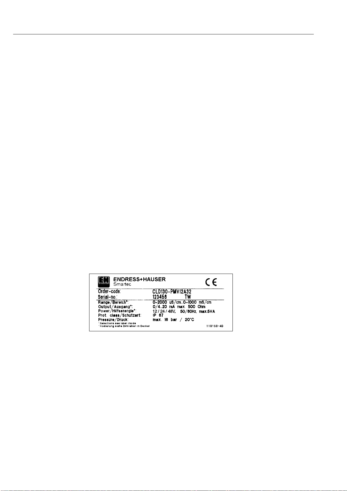
Fig. 1.1: Nameplate
Smartec CLD 130
1. General Smartec CLD 130
2
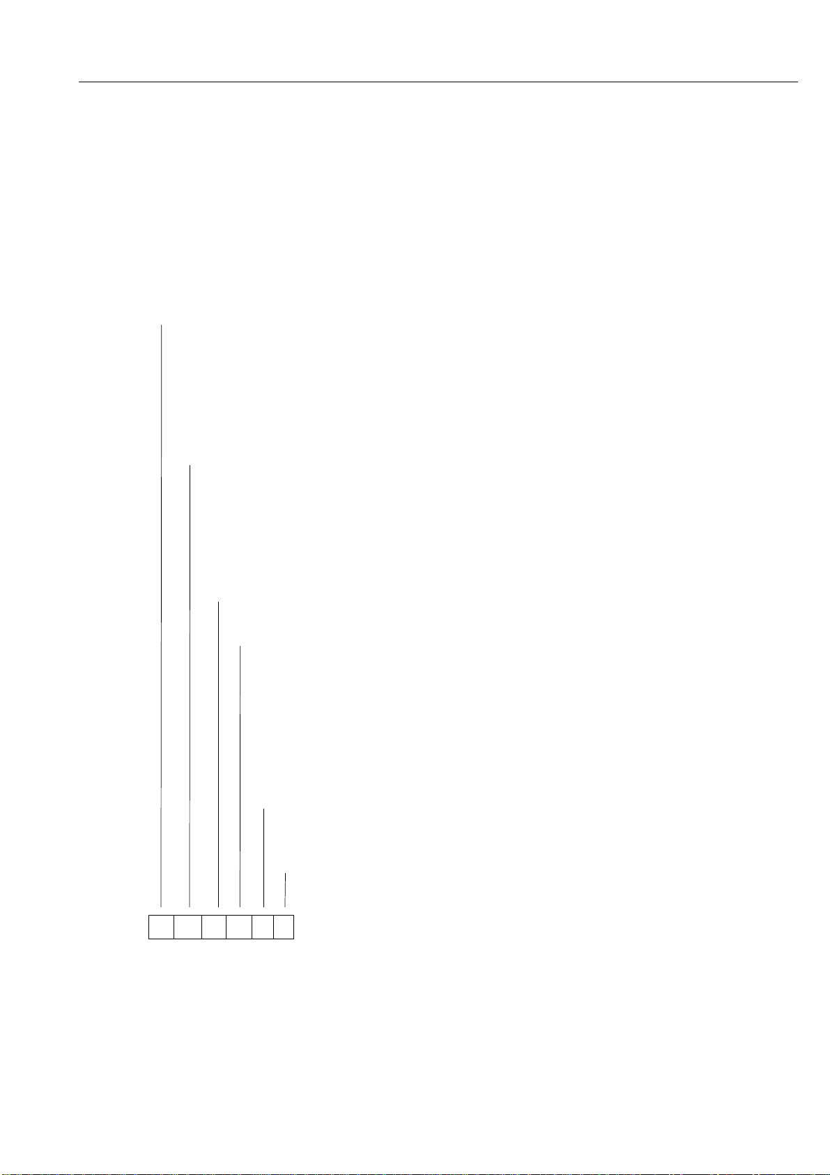
1.3 Order code
Inductive instrument Smartec CLD 130
Design
P Compact design with in situ measuring transmitter / PEEK
W Separate measuring transmitter with 5 m cable / PEEK
X Separate measuring transmitter with special cable length (max. 15 m) / PEEK
Version
MV1 Dairy fitting connection DN 50 to DIN 11851
RF1 Round flange DN40/PN10 and loose flange
TF1 Immersion sensor IP68 / loose fl. UP-GF DN50 / PN10 (W/X design only)
CS1 2" clamp fitting
ET1 Immersion version with round flange, l=2000mm
GE1 Internal thread G 1 1/2"
IF1 2" IDF flange
VA1 Varivent fitting for housing TN
Measuring ranges
0 0 ... 2000 µS/cm
1 0 ... 20 mS/cm
2 0 ... 200 mS/cm
3 0 ... 1000 mS/cm
4 20 / 2 mS/cm with remote switching
5 200 / 20 mS/cm with remote switching
6 1000 / 100 mS/cm with remote switching
ATC range
A ATC range 1 ... 3 %/K
Power supply
0 Power supply 230 V, 50 / 60 Hz
1 Power supply 110 V, 50 / 60 Hz
2 Power supply 200 V, 50 / 60 Hz
3 Power supply 24 V, 50 / 60 Hz
4 Power supply 48 V, 50 / 60 Hz
5 Power supply 100 V, 50 / 60 Hz
6 Power supply 127 V, 50 / 60 Hz
7 Power supply 240 V, 50 / 60 Hz
8 Power supply 24 V m. sep. DC/AC converter
Instrument output
0 0 ... 20 mA, max. 500 Ω
2 4 ... 20 mA, max. 500 Ω
CLD 130– ⇐complete order code
BE1LD130.CHP
Smartec CLD 130 1. General
3

2. Measuring system
2.1 Measuring principle
The test medium is a liquid conductor
coupling the magnetic field of two
magnetically isolated induction coils. The
AC voltage U1applied to coil T1is transmitted
to the second coil T2proportional to the
conductance G of the test medium. This
yields a linear relationship between the
conductance G and the output voltage U2
which is converted and rectified into a voltage
proportional to the conductance.
This measuring principle offers following
advantages:
•no electrodes, therefore no polarization
•faultless measurement in media or solutions
with a tendency to form deposits
A Pt 100 temperature sensor is fitted inside
the sensor to measure the temperature.
2.2 Sensor
The sensor is injection-moulded of chemically,
mechanically and thermally resistant PEEK
(polyether ether ketone), ensuring that it is
free of crevices and joints, and making it
biologically safe.
The sensor shaft contains the two induction
coils and a temperature sensor Pt 100 which
is in direct contact with the test medium.
The use of special elements and materials
makes the sensor suitable for continuous
operation at temperatures of up to + 100 °C,
and short-term operation at up to + 130 °C.
Therefore, Smartec can be sterilized.
The sensor is available in different mounting
variants with integrated or separate
measuring transmitter.
2.3 Measuring transmitter
The measuring transmitter
•determines the conductivity of the liquid,
and indicates the conductivity value based
on reference temperature 25 °C and
•supplies this measured value as current
(0 or 4 ... 20 mA) at the signal output.
The instrument requires power supply (see
cover label).
The actual measured value and the set
temperature coefficient can be read externally
through a viewglass in the housing cover.
Four basic measuring ranges can be freely
selected:
•0 ... 2000 µS/cm
•0 ... 20 mS/cm
•0 ... 200 mS/cm
•0 ... 1000 mS/cm
The zero point can be displaced within the
selected measuring range, increasing the
sensitivity, and thus spreading the range,
considerably. This permits precise
measurement even in media with slight
conductivity changes.
Medium
Chemical attack Resistance
Medium Concentr.
(%) Temp.
(°C) PVC-C PVDF PEEK
Nitric acid HNO35
up to 40
20
60
20
60
+
+
+
+
+
+
+
+
+
+
+
–
Phosphoric acid H3PO4up to 10 20
60 +
++
++
+
Caustic soda solution
NaOH 320
50
90
+
+
+
+
0
–
+
+
+
sodium hypochlorite
Labarraque's solution
NaOCl
diluted
aqueous 20
50
90
+
+
0
0
0
–
+
+
+
Fig. 2.2 Excerpt from resistance
tables for PVDF, PEEK
and PVC-C
Legend:
+ resistant
0 conditionally resistant
– not resistant
Fig. 2.1: The inductive conductivity
measuring principle
2. Measuring system Smartec CLD 130
4

2.4 Designs
2.4.1 Sensor with integrated
transmitter
The sensor with integrated measuring
transmitter including screw connection,
provides a complete measuring unit.
2.4.2 Sensor with separate
transmitter
The standard version provides the measuring
transmitter with 5 m connected cable. The
sensor is connected to the fitted cable plugs.
2.4.3 Immersion sensor with
integrated transmitter
The measuring system comprises:
Measuring transmitter with immersion pipe,
sensor and round flange.
2.4.4 Immersion sensor with
separate transmitter
The measuring system comprises:
Separate transmitter, immersion sensor IP 68
with connected cable, round flange with strain
relief for freely suspended sensor.
Power supply
Signal output
0 / 4 … 20 mA
Measuring cable
Double coaxial cable
double shielded with fitted
plugs for connection of
sensor
Power supply
Transmitter
Signal output 0 / 4 - 20 mA
7-pole connection
with cable
Power supply
Signal output
0/4-20mA
Fig. 2.3: Sensor with integrated
(left) transmitter
Fig. 2.5: Immersion sensor with
(right) integrated transmitter
Fig. 2.4: Measuring transmitter
(left) connected to separate
sensor via 5 m cable
Fig. 2.6: Immersion sensor with
(right) separate measuring
transmitter
BE1LD130.CHP
Smartec CLD 130 2. Measuring system
5
3. Installation
3.1 Sensor with integrated
transmitter
The Smartec measuring system is available in
different designs for all commonly used
mounting and installation versions for
industrial applications:
•Dairy fitting connection DN 50, DIN 11851
•Internal thread G 1 1/2"
•Varivent fitting
•2" IDF flange
•2" clamp fitting
•Round flange DN 40 / PN 10
The instrument is installed at the measuring
point using the selected connections, i.e.
dairy fitting connection (see fig. 3.1).
For installations in pipelines it must be
ensured that the sensor is mounted at a point
which is always fully flooded during the
measuring process.
If the sensor is mounted vertically onto the
pipeline, it should be installed in a culvert.
For measurements in high viscosity media
(e.g. emulsions) the sensor should be
installed in a pipe bend so that the media
flows directly through the measuring channel.
The version with integrated measuring
transmitter is suitable for use with continuous
medium temperatures of up to 90 °C and
ambient temperatures of up to 50 °C.
Note:
The suitable connection flange for
pipe or tank has to be provided
by customer.
➡155.5
min. 20
min.
DN 65
➭
Pg 16,
reduced
G 11/2"
118.5
250
ø34
107
85 22
Pg 16,
reduced
118.5
250
ø34
69
57
➳
➺
234
85
➑
234
85
➱
250
102
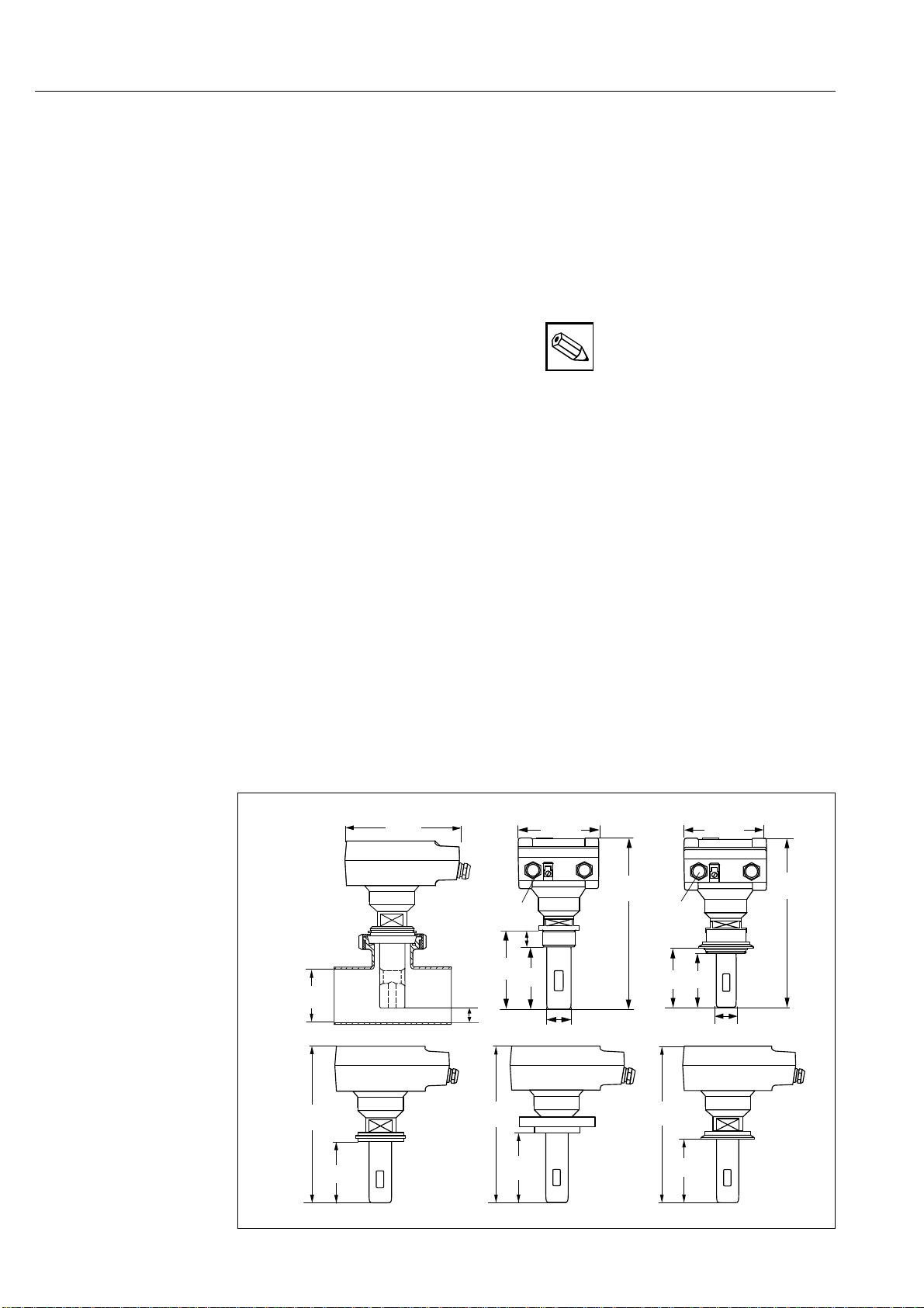
Fig. 3.1: Sensors with integrated
transmitter in the
connection head
➡Sensor with dairy fitting connection
DN 50, DIN 11851
➭Sensor with internal thread G 1
1
/
2
"
➳Sensor with Varivent fitting
➺Sensor with 2" IDF flange
➱Sensor with round flange
DN 40 / PN 10
➑Sensor with 2" clamp fitting
3. Installation Smartec CLD 130
6
3.2 Sensor with separate
transmitter
Smartec with a separate measuring
transmitter is available for industrial
applications with high permanent
temperatures (>90 °C) and hardly accessible
measuring points.
The sensor is mounted at the measuring point.
The measuring transmitter is then mounted
separately and connected to the sensor via a
5 metres long double shielded double coaxial
cable.
The ambient temperature of the measuring
transmitter may be max. + 60 °C.
Warning:
The ready-made cable must not be
shortened in any case!
230
102
➡
85
➳
85
➭
85
➺
85
G1
1/2"
➱➑
69
DN
40 DN
50
D 150 165
k 110 125
l1818
a6278
b1618
ak
D
b
D
l
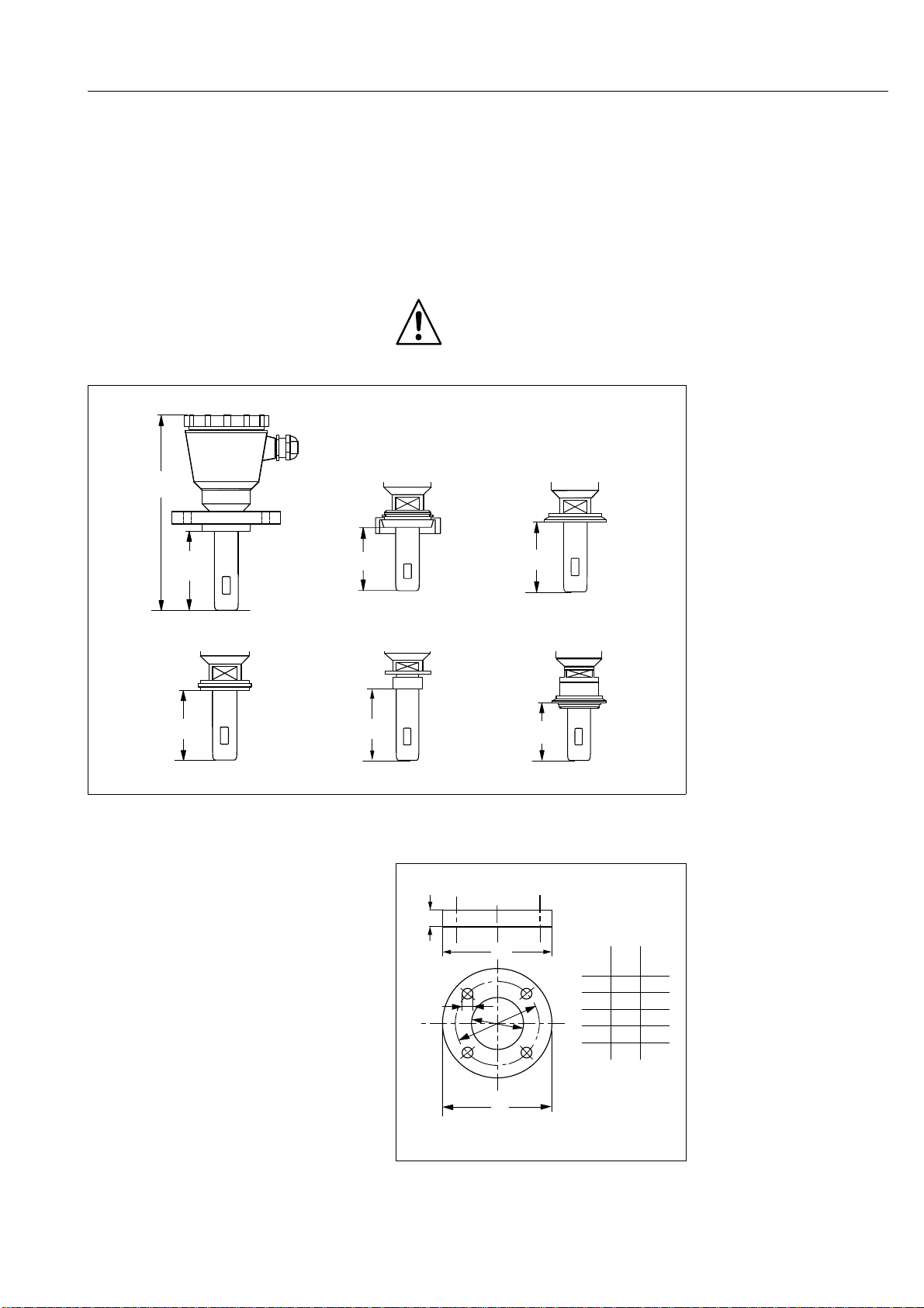
Fig. 3.2: Sensors with connection
head without measuring
transmitter
➡Sensor with dairy fitting connection
DN 40 / PN 10
➭Sensor with dairy fitting connection
DN 50, DIN 11851
➳Sensor with 2" clamp connection
➺Sensor with 2" IDF flange
➱Sensor with internal thread G 11/2"
➑Sensor with Varivent fitting
(stainless steel adapter)
Fig. 3.3: Dimensioned drawing
of the used flanges for the
corresponding installation
versions
BE1LD130.CHP
Smartec CLD 130 3. Installation
7

3.3 Immersion sensor with
integrated transmitter
Smartec as an immersion assembly with an
integrated measuring transmitter is used in
large basins or open channels.
The measuring signal (0/4 ... 20 mA) can be
transmitted across larger distances (up to a
maximum of 1000 m).
The immersion assembly is installed with a
round flange DN 50 / PN 10. It is made of
PVC-C and is available in different lengths
(400 bis 2000 mm).
This assembly can be used in temperatures
of up to 90 °C (permanent temperature 80 °C)
and under pressures of up to 6 bar (at 20 °C)
in closed containers.
3.4 Immersion sensor with
separate transmitter
For installation in tanks or other closed
containers, Smartec CLD 130 is available as
an immersion assembly with a separate
measuring transmitter.
The inductive sensor is mounted in the
assembly using a bayonet lock. The assembly
material PVC-C is resistant to aggressive
chemicals. For application in CIP systems, the
assembly is mounted in a V4A version using a
DN 65 dairy pipe fitting.
For open containers and channels the sensor
is mounted freely suspended with clamp
connection and strain relief.
In case of the IP 68 immersion sensor the
measuring cable is protected from the
medium by a pressure-proof silicone hose.
The cable gland in the immersion sensor is
mounted by means of a bayonet lock.
➡
Ø 123
Ø47
82
277
➭
86
172
82
Ø 123
Ø 47
Ø88
400 – 2000 mm immersion depth 220
82
63172
Pg 16
reduced
∅47
measuring
cable
∅49
Fig. 3.5: Immersion sensors for
measuring transmitters
➡Immersion sensor TF1 (ingress
protection IP 68)
with PVDF sensor cap,
2 m silicone hose and round
flange DN 50/PN 10
➭Immersion sensor ET 1 made of
PVC in different lengths
(400 to 2000 mm immersion depth)
with round flange DN 50 / PN 10
Fig. 3.4: Immersion sensor with
integrated transmitter
3. Installation Smartec CLD 130
8

Exchanging of the sensor
1. Unscrew Pg thread of cable duct on top
of the assembly (see fig. 3.5, ➡or ➭).
2. Loosen sensor by turning it anticlockwise
(bayonet lock ➑).
3. Withdraw the sensor part with protection
sleeve ➺from immersion tube ➡.
4. Unscrew Pg thread ➳of protection sleeve.
5. Take sensor out of guide notch of
protection sleeve and loosen plug
connections ➭,➱.
6. Assembe the sensor in reverse order.
Warning:
When assembling or disassembling
the sensor the Pg thread must be
unscrewed before pulling the
measuring cable (see fig. 3.5).
110
18
133
87
54
70
155
Ø 40
min.
9
Retaining
strap
Fig. 3.7: Mounting plate for wall
and post mounting of
separate measuring
transmitter
➡
➳
➑
➱
➭
➺
Fig. 3.6: Cable connection and
assembling of sensor
for immersion versions
3.5 Separate transmitter
The separate measuring transmitter can be
easily installed on wall and posts using a
mounting plate.
The mounting plate is secured to a wall using
3 screws and the supplied spacer bushes.
The transmitter is attached to pipes or posts
by means of a retaining strap.
The sensor cable with 4 plugs is introduced in
the sensor housing through the Pg thread.
Then put together the cable plugs, tighten
Pg 16 thread and screw cover on the
connection head.
BE1LD130.CHP
Smartec CLD 130 3. Installation
9

4. Electrical connection
4.1 Connection principles
Attention:
•The instrument must be grounded
before operation!
•If malfunctions cannot be
remedied, the instrument must be
removed from service and
protected against accidental
start-up.
Repair work can only be carried
out directly by the manufacturer or
by the Endress + Hauser service
organization.
Warning:
•Notes and warnings of these
operating instructions must be
strictly adhered to! Maintenance
work can only be carried out by
qualified personnel if the
instrument remains connected to
the power supply!
•The instrument is protected
against interference, pulse-shaped
transients, high frequency and
electrostatic discharges according
to the Namur recommendations,
IEC 801 und DIN VDE 0843.
However, this is only valid for a
properly grounded instrument with
a screened measured value output
line.
•For the separate version of the
instrument we recommend not to
wire the measuring line to the
sensor directly next to a
high-voltage line. If this is
unavoidable, embed measuring
line in a grounded steel pipe.
Note:
•This instrument has been built and
tested in accordance with VDE
0411, part 100, and left the
manufacturer's works in perfect
condition concerning safety
regulations.
•This instrument has been tested
under reference conditions
concerning electromagnetic
compatibility according to
EN 50081-2.
•Malfunctions of the instrument can
be remedied by means of the error
list in chapter 7.2 without requiring
intervention in the instrument itself.
Alterations to the instrument are
not allowed and make any
guarantee claim invalid.
•After installing and connecting the
instrument and sensors the whole
measuring system has to be
checked for function.
Instrument connection to
direct voltage mains
(24 V AC version)
Smartec CLD 130 can be operated in the
direct voltage mains by inserting of a DC/AC
converter:
DC/AC converter
Input voltage 15 bis 32 V DC
Output voltage 24 V AC 2%
Output frequency 50 Hz
Output power 4.5 VA
Order no. 50038935
KL1(A) KL2
0/4-20mA
PE
NL1
–+
PE
NL1PE
–+ AC
Power supply
24 V to 240 V AC
(see nameplate)
Fig. 4.1: Connection diagram for
sensor with integrated
transmitter
4.2 Sensor with integrated transmitter
4. Electrical connection Smartec CLD 130
10

4.3 Sensor with separate
transmitter
KL3KL4
0/4-20mA
KL1(A) KL2
KL5
Measuring cable
Pt 100
Measuring
transmitter
blk rd bn gn
Inductive
Sensor
21321321
+–
PE
PE N
L1PE N
L1
Pt 100
+–
AC
gnbnwtwtrdblk
wt wt
κ
Ι
Power supply
24 V to 240 V AC
(see nameplate)
Fig. 4.2: Connection diagram for
sensor with separate
transmitter
BE1LD130.CHP
Smartec CLD 130 4. Electrical connection
11

5. Start-up
5.1 Power-up
Before switching on, ensure that all
connections have been correctly made
according to chapter 4.
5.2 Instrument settings
Normally no settings need to be made since
the instrument has been preset at the factory
according to the order code.
The settings concerned are as follows:
•Measuring range and decimal point of
display,
•Signal output function (0 or 4 ... 20 mA),
•Mains voltage coding,
•Signal output variation and zero point
suppression, if ordered.
The settings are recorded on the inside of the
cover (see figure 6.1).
Any changes required should be made
according to chapter 6.
5.3 ATC setting
The automatic temperature compensation
(ATC) factor can be set externally on the
scaled ATC control (see chapter 6.2). If the
factor is not known refer to chapter 6.2.
5.4 Measuring mode
After applying the mains voltage, the
instrument must operate correctly and display
a temperature-compensated conductivity
value in mS/cm or µS/cm.
5. Start-up Smartec CLD 130
12
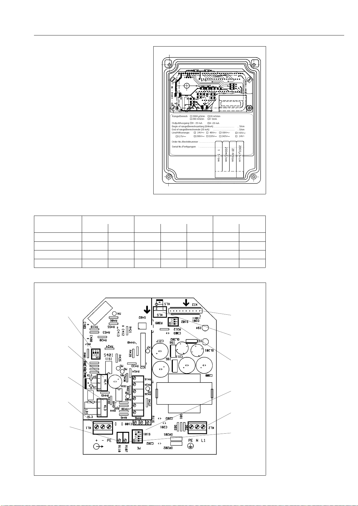
6. Operation
All information in the following chapters
relates to the items in figures 6.1 and 6.2.
6.1 Measuring range
change-over
The instrument has four measuring ranges
which can be changed over by means of
coding switches S 101 and S 401.
The decimal point in the display must be
adjusted with switch S 102 whenever the
measuring range is changed.
A corresponding measuring range plate can
be removed from the label in the cover and
inserted into the pocket on the rear of the
transparent front panel. The measuring range
plates are self-adhesive.
Measuring range Switch S 101 Switch S 102 Switch S 401
1212312
0 ... 2000 µS/cm –––––––
0 ... 20 mS/cm –––on –on –
0 - 200 mS/cm ––––on on on
0 - 1000 mS/cm on on –––on on
Measuring
range
change-over
S 401
Terminal 4
Receiving coil
Terminal 3
temperature
sensor
Pt 100
Terminal 1
signal output
Control R110
end of range
Display
connector
Terminal 5
Transmitting coil
Decimal point
change-over
S102
Change-over
signal output
S101
Terminal 2
Power supply
Control R107
start of range
Fig. 6.1 Inside view of cover with
measuring range plates
Fig. 6.2: Inside view Smartec
CLD 130 - componentry
with terminals and plugs
for measuring range
change-over
Table 6.1: Switching of
measuring range
BE2LD130.CHP
Smartec CLD 130 6. Operation
13

•If the temperature coefficient is known it is
set on the scaled ATC control on the front
panel using a screwdriver.
Typical temperature coefficients are:
Water > 1 µS/cm: 2.1 % / °C
Lye (NaOH) approx. 2 %: 1.9 % / °C
Acid (HNO3) up to 2 %: 1.6 % / °C
Salty solutions: 2.2 % / °C
Milk, beverages: 2.0 % / °C
•If the temperature coefficient is unknown
determine the coefficient as follows:
Determination of actual temperature
coefficient:
The reference temperature of automatic
temperature compensation is 25 °C. At this
temperature the setting of the ATC control has
no influence, this means the ATC is virtually
switched off.
•Carry out a measurement in the test
medium at 25 °C
•Note the display value
•Heat the test medium to operating
temperature
•Wait until the value of the measurement has
stabilized (adjustment time of temperature
sensor)
•Set the display to the value noted previously
(at 25 °C) using the ATC control.
The actual temperature coefficient for the
medium used is now indicated on the ATC
scale.
Note:
The temperature sensor in the
sensor requires approx. 10 minutes
to adjust to the changed
temperature. Therefore wait until
display has stabilized when the
temperature of the test medium has
changed.
Concentration
Temperature coefficient
Salts
Strong alkalis
Strong acids
Fig. 6.3: Concentration dependency
of the temperature
coefficient for several
electrolyte solutions
6.2 ATC adjustment
(automatical temperature
compensation)
6. Operation Smartec CLD130
14

6.3 Signal output change-over
The signal output can be switched to
0 ... 20 mA or 4 ... 20 mA using switch S 101
(see fig. 6.2).
6.4 Signal output assignment
(MR versions 0/1/2/3)
The signal output can be spread continuously.
Also the beginning of the signal output can be
continuously set within 0 ... 80 % of the
measuring range.
This enables to extract virtually any window
from the measuring range and output it as a
current signal.
Procedure:
•Connect an ammeter 0 ... 20 mA to the
signal output.
•Simulate the conductance at which the
signal output should be 0 or 4 mA
(conductance simulation see chapter 7.3).
•Set 0 or 4 mA with control R 107 (see
fig. 6.2).
•Simulate the conductance at which the
signal output should be 20 mA.
•Set 20 mA with control R 110 (see fig. 6.2).
Output range Switch S 101
345
0 ... 20 mA –on –
4 ... 20 mA on –on
Example:
A signal output of 0 ... 20 mA corresponding
to 100 ... 150 mS / cm is to be set in the range
0 ... 200 mS / cm.
This is possible following the above
instructions. The spread is factor 4 which
equals 25 % of the measuring range, the zero
point suppression corresponding to 50 % of
the measuring range.
Then align the equipment at 0 mA for 50 Ohm
and 20 mA for 33.3 Ohm (see chapter 7.3.)
20 mA
4mA
20 80 100
Max.
spread Min.
spread
Max.
spread
Allowed simulation value end of measuring range
Selected measuring range (%)
Allowed simulation value start of measuring range
Control
R 110
Control
R 107
Selected
signal output
0to20mAor
0to20mA
Fig. 6.4: Assignment of measuring
range - current output
Table 6.2: Switching of output range
BE2LD130.CHP
Smartec CLD 130 6. Operation
15

6.5 Remote switching
of current output
(MR versions 4/5/6)
With the option remote switching of current
output the following measuring ranges are
usable:
•1000 mS / cm
•200 mS / cm
•20 mS / cm
Remote switching spreads current output and
measuring range by factor 10, e.g. the
original indication range from
•0 or 4 ... 20 mA
corresponding to 0 ... 200 mS / cm
changes to
•0 or 4 ... 20 mA
corresponding to 0 ... 20 mS / cm.
Note:
Zero-point adjustment of measured
value output is not possible by
remote switching!
Control connection
remote switching Assigned
current output
0 / 4 - 20 mA)
Selected measuring
range
Selected measuringrange
10
Terminal 1 A
signal output
Terminal 1 B
remote switching
Fig. 6.5: Inside view of Smartec
CLD 130 - remote
switching connection
Table 6.3: Measuring range
assignment for remote
switching
6. Operation Smartec CLD130
16

7. Maintenance and
troubleshooting
7.1 Maintenance
Measuring transmitter and sensor are
maintenance-free. No parts wear out.
7.2 Troubleshooting
Error Possible cause Remedy
No display
No signal output
(display present)
Display unsteady, flickers,
susceptible to faults
Display 1---
Display 000
No power supply
Output line interrupted
Grounded conductor not
connected and / or shield of
output line not connected
Measuring range exceeded
Sensor does not immerse into
the medium
Check mains supply
Check line, terminals and
connected analyzer
Check grounded conductor
connection (should be short
and have a large cross-section)
use a shielded cable and
connect shield to grounded
conductor
Select the next higher range
(see chapter 6.1)
Check flow of pipe system or
level at tank installation as well
as installation position (air
bubbles) Table 7.1: Troubleshooting, cause
and remedy
BE2LD130.CHP
Smartec CLD 130 7. Maintenance and troubleshooting
17

7.3 Instrument function test
Simulation values for simulating the
conductance of the medium
For simulation purposes a wire is looped
through the sensor (looped through the
central hole and out through one of the holes
at the side).
The simulation resistance is connected to this
wire loop, either as an individual resistance or
using a resistance decade.
A large wire cross-section and low transition
resistances must be ensured when high
conductance values, i.e. low resistance are
involved (short connections, solder carefully!).
For intermediate values, the simulation
resistance is calculated according to the
following fomula:
R=1
Conductance ⋅k
Conductance in S/cm yields R in ohm
Conductance in mS/cm yields R in kohm
Conductance in µS/cm yields R in Mohm
k (cell constant) = 5
Attention:
The displayed value will only
correspond with the siumulation
value if
•the temperature is 25 °C or
•a simulation resistance of
109.72 ohm is connected to
terminal 3 instead of the Pt 100
sensor.
•Precision resistances must be
used for simulation, allowed
tolerance 0.1 %.
•The transition resistances for wire
coil and soldering joint must be
considered for the allowed
tolerance value.
Conductance Simulation value
100 µS/cm 50 kOhm
200 µS/cm 25 kOhm
500 µS/cm 10 kOhm
1000 µS/cm 5 kOhm
2000 µS/cm 2.5 kOhm
5 mS/cm 1 kOhm
10 mS/cm 500 Ohm
20 mS/cm 250 Ohm
50 mS/cm 100 Ohm
100 mS/cm 50 Ohm
200 mS/cm 25 Ohm
500 mS/cm 10 Ohm
1000 mS/cm 5 Ohm
7. Maintenance and troubleshooting Smartec CLD130
18

8. Technical data
Measuring transmitter
Measuring ranges (switchable). . . . . . . . . . . . . . . . 0 ... 2000 µS/cm; 0 ... 20/200/1000 mS/cm
ATC range (standard) . . . . . . . . . . . . . . . . . . . . . . . . . . . . . . . . . . 1.0 ... 3 %/K (–5 ... +105 °C)
(option). . . . . . . . . . . . . . . . . . . . . . . . . 0.5 ... 3 %/K (–5...+105°C); 2.1 ... 6 %/K (0 ... +40 °C)
ATC reference temperature. . . . . . . . . . . . . . . . . . . . . . . . . . . . . . . . . . . . . . . . . . . . . . . . . 25 °C
Measured value deviation
Display. . . . . . . . . . . . . . . . . . . . . . . . . . . . . . . . . . . . . . . . . . . . . 1 % of meas. range final value
Signal output . . . . . . . . . . . . . . . . . . . . . . . . . . . . . . . . . . . . . . . . 1 % of meas. range final value
Smallest measured value . . . . . . . . . . . . . . . . . . . . . . . . . . . . . . . . . . . . . . . . . . . . . . 100 µS/cm
Power supply AC. . . . . . . . . . . . . . . . 110/127/220 V, 50 ... 60 Hz; 100/200/240 V, 50 ... 60 Hz
........................................ 12/24/48V,50...60Hz;–10 % ... +15 %
Power supply DC. . . . . . . . . . . . . . . . . . . . . . . . . . . . . . . . . . . . with seperate DC-AC converter
Power consumption. . . . . . . . . . . . . . . . . . . . . . . . . . . . . . . . . . . . . . . . . . . . . . . approx. 4.5 VA
Signal output . . . . . . . . . . . . . . . . . . . . . . . . . . . . . . . . . . . . . . . . . . . 0 / 4 ... 20 mA, switchable
Load........................................................... max.500Ohm
Measured value output spread . . . . . . . . . . . . . . . . . . . . . . . . . . . . . . . . . 20 % ... 100 % of MR
Measured value zero shift . . . . . . . . . . . . . . . . . . . . . . . . . . . . . . . . . . . . . . . 0 % ... 80 % of MR
Display. . . . . . . . . . . . . . . . . . . . . . . . . . . . . . . . . . . . . . . . . . . 13.5 mm LC display, 3 1/2digits;
Permissible operating temperature (with integrated transmitter) . . . . . . . . . . . . . –10 ... +50 °C
Permissible operating temperature (with separate transmitter) . . . . . . . . . . . . . . –10 ... +60 °C
Permissible storage temperature . . . . . . . . . . . . . . . . . . . . . . . . . . . . . . . . . . . . . –25 ... +80 °C
Permissible humidity . . . . . . . . . . . . . . . . . . . . . . . . . . . . . . . . . . . . . . . . . . . . . 5 % ... 95 % rel.
Ingress protection (DIN 40050). . . . . . . . . . . . . . . . . . . . . . . . . . . . . . . . . . . . . . . . . . . . . . IP 67
Dimensions . . . . . . . . . . . . . . . . . . . . . . . . . . . . . . . . . . . . . . . . . . 160 x 120 x 70 mm (HxWxD)
Housing material . . . . . . . . . . . . . . . . . . . . . . . . . . . . . . . . . . . . . . . . . . . . . . coated aluminium,
Terminal wire cross section. . . . . . . . . . . . . . . . . . . . . . . . . terminals 2.5 mm2; sensor 1.5 mm2
Housing ducts . . . . . . . . . . . . . . . . . . . . . . . . . . . . . . . 2 x Pg 9 glands; (replaceable by Pg 16)
Sensor connection Pg 16 (only for separate sensor)
Sensor with integrated transmitter
Sensor material . . . . . . . . . . . . . . . . . . . . . . . . . . . . . . . . . . . . . . PEEK (Polyether-ether-ketone)
Operating temperature . . . . . . . . . . . . . . . . . . . . . . . . . . . . . –5 ... +110 °C (permanent temp.)
Temperature sensor . . . . . . . . . . . . . . . . . . . . . . . . . . . . . . . . . . . . . . . . . . . . . . . Pt 100, built-in
Pressure. . . . . . . . . . . . . . . . . . . . . . . . . . . . . . . . . . . . . . . . . . . . . . . . . . . . max. 16 bar (20 °C)
Shaft immersion length . . . . . . . . . . . . . . . . . . . . . . . . . . . . . . . . . . . . . . . . . . . . . . . . . . . 85 mm
Pipe cross section . . . . . . . . . . . . . . . . . . . . . . . . . . . . . . . . . . . . . . . . . . . . . . . . . . . min. DN 65
Weight................................................................ 0.5kg
Mounting versions . . . . . . . . . . . . . . . . . . . . . . . . . . . . . . . . dairy pipe fitting DN 50, DIN 11851
............................................ internalthreadG11/2"; 2" IDF flange
............................................................. 2"clampfitting
................................................... roundflangeDN40/PN10
. . . . . . . . . . . . . . . . . . . . . . . . . . . . . . . . . . . . . . . . . . . . . . . . . . . . . . immersion sensor IP 68
Sensor with separate transmitter
Mounting versions . . . . . . . . . . . . . . . . . . . . . . . . . . . . as above, add. immersion sensor IP 68
Cable length and type . . . . . . . . . . . . . . . . . . . . . . . . . . . . . . . . . . . . 5 m long, pre-assembled
Cable connection . . . . . . . . . . . . . . . . . . . . . . . . . . . . . . . . permanently connected to sensor;
. . . . . . . . . . . . . . . . . . . . . . . . . . . . . . . . . . . . . . . . . . . . . . with terminals in meas. instrument
Immersion sensor (integrated and separate measuring transmitter)
Pipe material . . . . . . . . . . . . . . . . . . . . . . . . . . . . . . . . . . . . . . . . . . . . . . . . . . . . . . . . . . . PVC-C
Pipe length. . . . . . . . . . . . . . . . . . . . . . . . . . . . . . . . . . . . . . . . . . . . . . . . . . . . . 400 ... 2000 mm
Installation (compact version) . . . . . . . . . . . . . . . . . . . . . . . . . . . . . round flange DN 50 / PN 10
Installation (separate version) . . . . . . . . . round flange DN 50 / PN 10; dairy pipe fitting DN 65
Temperature . . . . . . . . . . . . . . . . . . . . . . . . . . . . . . . . . . . . . . . . . . . . . . . . . . . . . . . max. 80 °C
Pressure. . . . . . . . . . . . . . . . . . . . . . . . . . . . . . . . . . . . . . . . . . . . . . . . . . . . . max. 6 bar (20 °C)
Immersion sensor
Ingress protection . . . . . . . . . . . . . . . . . . . . . . . . . . . . . . . . . . . . . . . . . . . . . . . . . . . . . . . . IP 68
Material of protection cap . . . . . . . . . . . . . . . . . . . . . . . . . . . . . . . . . . . . . . . . . . . . . . . . . . PVDF
Material protection hose . . . . . . . . . . . . . . . . . . . . . . . . . . . . . . . . . . . . . . . . . . . . . . . . . silicone
Length..............................................................2000mm
Installation . . . . . . . . . . . . . . . . . . . . . . . . . . . . . . . . . . . . flange DN 50 / PN 10 with strain relief
. . . . . . . . . . . . . . . . . . . . . . . . . . . . . . . . . . . . . . . . . . . . . . . oval flange or mounting bracket
BE2LD130.CHP
Smartec CLD 130 8. Technical data
19
Table of contents


