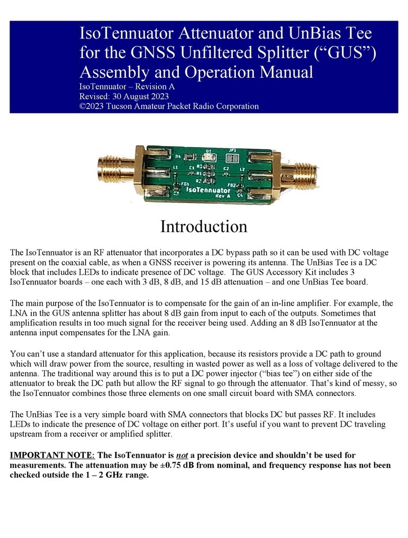
Neousys Technology NSIO-LTE-7455 User manual

Neousys Technology Inc.
NSIO-LTE-7455
User Manual
Revision 1.0

Table of Content
Table of Contents
Table of Contents...................................................................................................................2
Legal Information...................................................................................................................3
Contact Information...............................................................................................................4
Declaration of Conformity.....................................................................................................4
Copyright Notice....................................................................................................................5
Safety Precautions.................................................................................................................6
Service and Maintenance ......................................................................................................7
ESD Precautions....................................................................................................................7
About This Manual.................................................................................................................8
1Introduction
1.1 Specification of NSIO-LTE-7455..............................................................................10
1.2 Dimension................................................................................................................. 11
1.2.1 Top View With Modem Module..........................................................................11
1.2.2 Top view without the modem module................................................................11
1.2.3 Top View of Modem Module..............................................................................12
2System Overview
2.1 Unpacking.................................................................................................................13
2.2 NSIO-LTE-7455 module.............................................................錯誤! 尚未定義書籤。
2.3NSIO-LTE-7455 Daughterboard...............................................................................15
3System Installation
3.1 Disassembling the System Enclosure....................................................................17
3.2 NSIO-LTE-7455 Module Installation ........................................................................17
3.2.1 mini-PCIe Daughterboard Installation...............................................................17
3.2.2 LTE Module Installation.....................................................................................19
4Software and Firmware Installation
4.1 Windows®Operation................................................................................................22
4.2 Terminal Emulator Access.......................................................................................24

Legal Information
Legal Information
All Neousys Technology Inc. products shall be subject to the latest Standard
Warranty Policy
Neousys Technology Inc. may modify, update or upgrade the software, firmware or
any accompanying user documentation without any prior notice. Neousys
Technology Inc. will provide access to these new software, firmware or
documentation releases from download sections of our website or through our
service partners.
Before installing any software, applications or components provided by a third party,
the customer should ensure that they are compatible and interoperable with Neousys
Technology Inc. product by checking in advance with Neousys Technology Inc. The
customer is solely responsible for ensuring the compatibility and interoperability of
the third party’s products. The customer is further solely responsible for ensuring its
systems, software, and data are adequately backed up as a precaution against
possible failures, alternation, or loss.
For questions in regards to hardware/ software compatibility, customers should
contact Neousys Technology Inc. sales representative or technical support.
To the extent permitted by applicable laws, Neousys Technology Inc. shall NOT be
responsible for any interoperability or compatibility issues that may arise when (1)
products, software, or options not certified and supported; (2) configurations not
certified and supported are used; (3) parts intended for one system is installed in
another system of different make or model.

Contact Information/ Declaration of Conformity
Contact Information
Headquarters
(Taipei, Taiwan)
Neousys Technology Inc.
15F, No.868-3, Zhongzheng Rd., Zhonghe Dist., New Taipei City, 23586, Taiwan
Tel: +886-2-2223-6182 Fax: +886-2-2223-6183 Email, Website
Americas
(Illinois, USA)
Neousys Technology America Inc.
3384 CommercialAvenue, Northbrook, IL 60062, USA
Tel: +1-847-656-3298Email, Website
China Neousys Technology (China) Ltd.
Room 612, Building 32, Guiping Road 680, Shanghai
Tel: +86-2161155366Email, Website
Declaration of Conformity
FCC This equipment has been tested and found to comply with the limits for a Class
A digital device, pursuant to part 15 of the FCC Rules. These limits are
designed to provide reasonable protection against harmful interference when
the equipment is operated in a commercial environment. This equipment
generates, uses, and can radiate radio frequency energy and, if not installed
and used in accordance with the instruction manual, may cause harmful
interference to radio communications. Operation of this equipment in a
residential area is likely to cause harmful interference in which case the user will
be required to correct the interference at own expense.
CE The product(s) described in this manual complies with all applicable European
Union (CE) directives if it has a CE marking. For computer systems to remain
CE compliant, only CE-compliant parts ma
y be used. Maintaining CE
compliance also requires proper cable and cabling techniques.

Copyright Notice
Copyright Notice
All rights reserved. This publication may not be reproduced, transmitted,
transcribed, stored in a retrieval system, or translated into any language or
computer language, in any form or by any means, electronic, mechanical,
magnetic, optical, chemical, manual or otherwise, without the prior written
consent of Neousys Technology, Inc.
Disclaimer This manual is intended to be used as an informative guide only and is subject
to change without prior notice. It does not represent commitment from Neousys
Technology Inc. Neousys Technology Inc. shall not be liable for any direct,
indirect, special, incidental, or consequential damages arising from the use of
the product or documentation, nor for any infringement on third party rights.
Patents and
Trademarks
Neousys, the Neousys logo, Expansion Cassette, MezIOTM are registered
patents and trademarks of Neousys Technology, Inc.
Windows is a registered trademark of Microsoft Corporation.
Intel®, Core™ are registered trademarks of Intel Corporation
NVIDIA®, GeForce® are registered trademarks of NVIDIA Corporation
Qualcomm is a registered trademark of Qualcomm Incorporated.
All other names, brands, products or services are trademarks or registered
trademarks of their respective owners.

Safety Precautions
Safety Precautions
Store and transport the mini-PCIe card in the antistatic bag
Only remove it from the antistatic bag when it is ready to be installed
Read these instructions carefully before you install, operate, or transport the
module or system.
When installing/ servicing modules in the system, remove the system from DIN
rail or mount and place it on a flat and sturdy surface/ location
Install the power socket outlet near the system where it is easily accessible
Secure each system module(s) using its retaining screws
Place power cords and other connection cables away from foot traffic. Do not
place items over power cords and make sure they do not rest against data
cables
Shutdown, disconnect all cables from the system and ground yourself before
touching internal modules
Ensure that the correct power range is being used before powering the device
Should the module fail, arrange for a replacement as soon as possible to
minimize down-time
If the system is not going to be used for a long time, disconnect it from mains
(power socket) to avoid transient over-voltage

Service and Maintenance/ ESD Precautions
Service and Maintenance
ONLY qualified personnel should service the system
Shutdown the system, disconnect the power cord and all other cable
connections before servicing the system
When replacing/ installing additional components (expansion card, memory
module, etc.), insert them as gently as possible while assuring proper
connector engagement
ESD Precautions
Handle add-on module, motherboard by their retention screws or the module’s
frame/ heat sink. Avoid touching the PCB circuit board or add-on module
connector pins
Use a grounded wrist strap and an anti-static work pad to discharge static
electricity when installing or maintaining the system
Avoid dust, debris, carpets, plastic, vinyl and styrofoam in your work area.
Do not remove any module or component from its anti-static bag before it is
ready for installation

About This Manual
8
About This Manual
This manual introduces and demonstrates installation procedures of Neousys
NSIO-LTE-7455, an mPCIe Cat. 6 LTE module.
Revision History
Version Date Description
1.0 Jul. 2020 Initial release

NSIO-LTE-7455
9
1 Introduction
Neousys Technology NSIO-LTE-7455 is an add-on LTE module for industrial embedded
systems based on the Sierra EM7455 LTE cellular module in mPCIe card
specifications.
Neousys NSIO-LTE-7455 is a scalable radio module powered by EM7455 LTE solution.
It is a certified industrial-grade modem with a small form factor design that offers robust
cellular connectivity to M2M devices, industrial-grade computers, and in-vehicle
computers. At 5mm thin, its compact design suits applications that are space-limited.
Capable of up to Cat. 6 (2CA, 300Mb/s), it is an economical and effective alternative to
save on cost and complex certification processes.

NSIO-LTE-7455
10
1.1 Specification of NSIO-LTE-7455
Applicable region North America/ EMEA
Bands
4G/ LTE Bands: B1, B2, B3, B4, B5, B7, B8, B12, B13, B20, B25,
B26, B29, B30, B41
3G/ HSPA+/ UMTS Bands: B1, B2, B3, B4, B5, B8
Satellite location service
Galileo
GLONASS
GPS
BeiDou
Antenna configuration MIMO 2x2
Data speed
Cat. 6
Download: up to 300Mb/s
Upload: up to 50Mb/s
SIM slot 2FF SIM connector
Supported OS
Windows®7
Windows® 8.1
Windows® 10
Linux
Control option APIs, AT commands
Power consumption LTE: 1.5A (Max.)
Idle: 2.6mA
Dimension 55.7(L) x 30(W) x 5(H) mm
Operating temperature -25°C ~ 60°C
Regulatory compliance CE/ FCC/ RoHS
NOTE
The NSIO-LTE-7455 is designed to operate within Neousys systems only!
It MUST NOT be sold independently as an add-on module for third party systems!

NSIO-LTE-7455
11
1.2 Dimension
1.2.1 Top View With Modem Module
1.2.2 Top view without the modem module

NSIO-LTE-7455
12
1.2.3 Top View of Modem Module

NSIO-LTE-7455
13
2 System Overview
Upon receiving and unpacking your NSIO-LTE-7455, please check immediately if the
package contains all the items listed in the following table. If any item(s)are missing or
damaged, please contact your local dealer or Neousys Technology.
2.1 Unpacking
Item Description Qty
1 mini-PCIe SIM card daughter board 1
2 EM-7455 LTE module 1
3 Screw pack 1

NSIO-LTE-7455
14
2.2 NSIO-LTE-7455 module
The NSIO-LTE-7455 module features the MAIN, GPS and AUX connector and gold
finger connectors at opposite ends.
No. Item Description
1 MAIN
connector
This is module's main antenna connector for receiving LTE RF
signals.
2 GPS
connector This is LTE module's main connector for the GPS antenna.
3 AUX
connector
AUX is the secondary RF input for the reception of LTE RF
signals for Down-Link MIMO 2 x 2 radio; a compulsory hardware
component for category 4 LTE user equipment. This can also be
connected as an alternative reception option for GPS.
NOTE
The connector pins of NSIO-LTE-7455 has a nominal characteristic impedance of 50
Ωand must be connected to an Rx antenna through a 50Ωtransmission line to
allow proper RF reception.

NSIO-LTE-7455
15
2.3 NSIO-LTE-7455 Daughterboard
The NSIO-LTE-7455 daughterboard features mini-PCIe connector gold finger, LTE
module insertion slot, SIM card slot, two screw holes to for securing the daughterboard
and screw-mount for securing the LTE module.
No. Item Description
1 mini-PCIe
connector pin 1 Pin 1 of the mini-PCIe connector.
2 mini-PCIe
connector pin 51 Pin 51 of the mini-PCIe connector.
3 LTE module slot The LTE module is inserted into the slot after the
daughterboard has been installed.
4 SIM card slot The SIM card holds one 2FF SIM card
5 Daughterboard
screw hole
The two screw holes are used for securing the
daughterboard.
6 LTE module
screw-mount The screw-mount is used for securing the LTE module.

NSIO-LTE-7455
16
3 System Installation
Before disassembling your system enclosure to install NSIO-LTE-7455 Cat. 6 LTE
module, please make sure you have done the following:
It is recommended that only qualified service personnel should install and service
this product to avoid injury or damage to the system.
Please observe all ESD procedures at all times to avoid damaging the equipment.
Before disassembling your system, please make sure you have the module/
component you wish to install at hand and have all the necessary tools.
Before disassembling your system, please make sure the system has powered off,
all cables and antenna (power, video, data, etc.) are disconnected.
Place the system on a flat and sturdy surface (remove from mounts or out of server
cabinets) before proceeding with the installation/ replacement procedure.

NSIO-LTE-7455
17
3.1 Disassembling the System Enclosure
The NSIO-LTE-7455 module is a Cat.6 LTE module designed to operate on Neousys
systems with a mini-PCIe interface.
To uninstall your system, please refer to the user manual of your system for
disassembly instructions and locate the mini-PCIe slot.
3.2 NSIO-LTE-7455 Module Installation
NOTE
For demonstration purposes, the Neousys POC-351VTC will be used to illustrate the
installation procedure.
The antenna and antenna cable are not included and must be purchased separately.
The installation process for NSIO-LTE-7455 starts off with the installation of the
daughterboard and SIM card. The LTE module and antenna is then installed after the
daughterboard has been secured
3.2.1 mini-PCIe Daughterboard Installation
1. The daughterboard cannot be secured if your NSIO-LTE-7455 module is installed
onto the daughterboard. Please separate the NSIO-LTE-7455 module from the
daughterboard by removing the flathead screw indicated in the illustration below.
2. Insert the SIM card into the daughterboard’s SIM card slot. You MUST install to
this SIM slot in order to operate with the NSIO-LTE-7455 module.

NSIO-LTE-7455
18
Insert SIM card Fully inserted SIM card
3. Locate the mini-PCIe slot on the system motherboard and insert the
daughterboard into the slot at an approximately 45-degree angle.
4. Gently push the daughterboard down to meet the stand-mount so the
daughterboard is horizontal with the system motherboard. Secure the
daughterboard with the supplied flathead screw or screws if you have two
stand-mounts to secure the mini-PCIe daughterboard.

NSIO-LTE-7455
19
3.2.2 LTE Module Installation
1. To install the LTE module, insert it at an approximately 45-degree angle.
2. Gently push the LTE module down to meet the stand-mount on the daughterboard
so the LTE module is horizontal with the daughterboard. Secure the LTE module
with the supplied flathead screw.

NSIO-LTE-7455
20
3. Clip-on the module’s antenna to the MAIN and AUX connector for optimum
reception. For details please refer to the EM7455 product technical specifications.
For demonstration purposes, the illustration below shows only the MAIN cable
connected.
4. Locate and remove one of the antenna covers from the enclosure.
Front panel antenna openings COM port panel antenna openings
5. Secure the SMA antenna connector, refer to the system's manual to reassemble
the enclosure and attach the external antenna.
Table of contents
Other Neousys Technology Control Unit manuals
