MG R7LWTU User manual

EM-7815 Rev.3 P. 1 / 15
MG CO., LTD. www.mgco.jp
5-2-55 Minamitsumori, Nishinari-ku, Osaka 557-0063 JAPAN
INSTRUCTION MANUAL
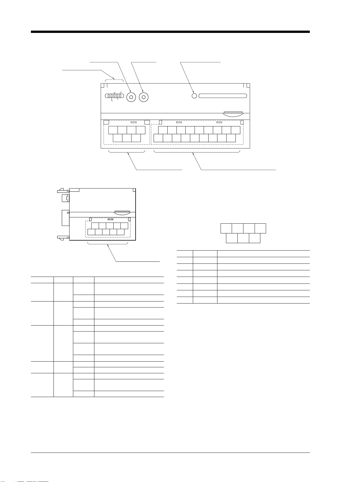
MULTI POWER MONITORING MODULE
(clamp-on current sensor CLSE, LONWORKS)MODEL R7LWTU
BEFORE USE ....
Thank you for choosing us. Before use, please check con-
tents of the package you received as outlined below.
If you have any problems or questions with the product,
please contact our sales office or representatives.
■PACKAGE INCLUDES:
Multi power monitoring module or extension module ......(1)
NeuronID label....................................................................(2)
■MODEL NO.
Confirm Model No. marking on the product to be exactly
what you ordered.
■INSTRUCTION MANUAL
This manual describes necessary points of caution when
you use this product, including installation, connection and
basic maintenance procedures.
The PC Configurator Software can use “monitoring meas-
ured values” and “loop test” functions for the R7LWTU. For
detailed information on the PC configuration, refer to the
PMCFG users manual. The PMCFG PC Configurator Soft-
ware is downloadable at our web site.
POINTS OF CAUTION
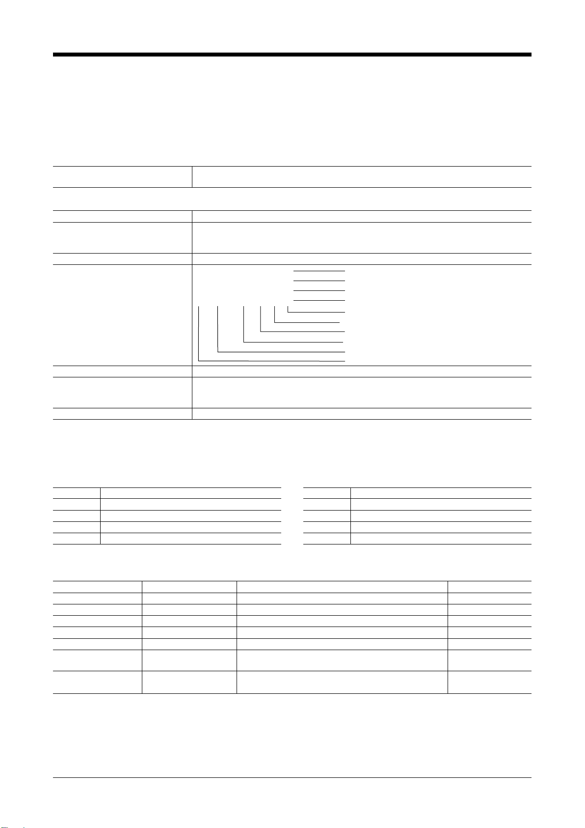
■POWER INPUT RATING & OPERATIONAL RANGE
• Locate the power input rating marked on the product and
confirm its operational range as indicated below:
100 – 240V AC rating: 85 – 264V, 50/60 Hz
Basic module < 5VA
Basic module + Extension module < 6VA
110 – 240V DC rating: 99 – 264V
Basic module < 1.5W
Basic module + Extension module < 2W
■GENERAL PRECAUTIONS
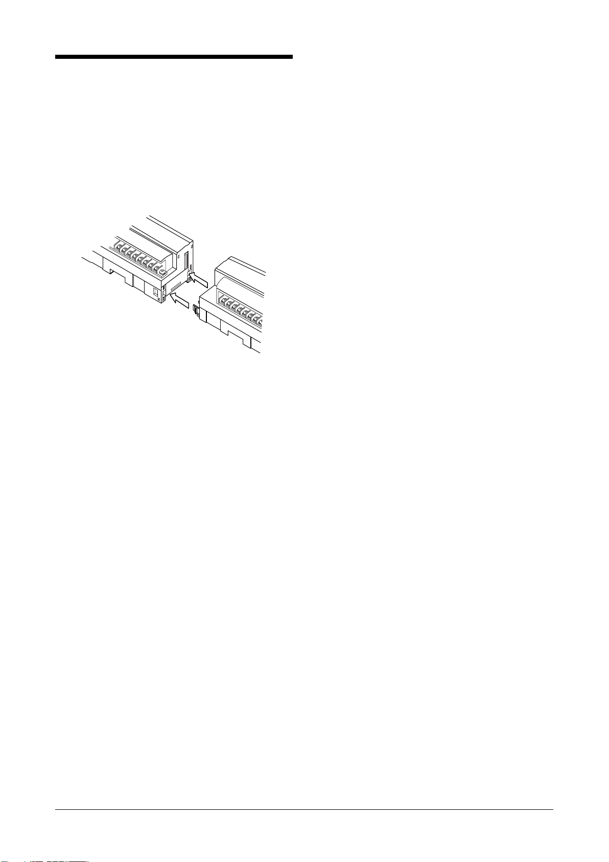
• Before you remove or mount the unit, turn off the power
supply and input signal for safety.
■ENVIRONMENT
• Indoor use.
• When heavy dust or metal particles are present in the
air, install the unit inside proper housing with sufficient
ventilation.
• Do not install the unit where it is subjected to continuous
vibration. Do not subject the unit to physical impact.
• Environmental temperature must be within -10 to +55°C
(14 to 131°F) with relative humidity within 30 to90% RH
in order to ensure adequate life span and operation.
■WIRING
• Wiring to the unit must be conducted by qualified service
personnel.
• Do not install cables close to noise sources (relay drive
cable, high frequency line, etc.).
• Do not bind these cables together with those in which
noises are present. Do not install them in the same duct.
■AND ....
• The unit is designed to function as soon as power is sup-
plied, however, a warm up for 10 minutes is required for
satisfying complete performance described in the data
sheet.

R7LWTU
EM-7815 Rev.3 P. 2 / 15
MG CO., LTD. www.mgco.jp
5-2-55 Minamitsumori, Nishinari-ku, Osaka 557-0063 JAPAN
COMPONENT IDENTIFICATION
■BASIC MODULE
ERR SVCE
ONLINETX/RX
PWR
4567
123
10 11 12 13
2341
15 16 17 18
7896
14
5
Voltage/Current/Discrete Input Terminals
SERVICE RESET
CNFG.
Status Indicator LED
PC Configurator Jack
Reset Switch
Service Switch
LONWORKS, Power Supply
Terminals
■EXTENSION MODULE
Discrete Input Terminals
786910
23145
■STATUS INDICATOR LED
ID COLOR STAT U S FUNCTION
PWR Green ON Internal power 5V normal
operating
OFF
Internal power 5V abnormality
ONLINE Green
ON Online
Blink
≈2 Hz Wink message received
OFF Abnormality
ERR Red
ON
Writing in non-volatile memory
Blink
≈ 0.5 Hz No input or input overflow
Blink
≈2 Hz Abnormality
OFF Normal operating
TX/RX Green ON In communication
OFF No connection
SVCE Green
ON Internal program error
Blink
≈ 0.5 Hz No network service
OFF Normal operating
■SERVICE SWITCH
Used to identify the node in LONWORKS network configura-
tion.
■RESET SWITCH
Used to reset the Neuron Chip. Press the switch behind the
front cover to reset.
Control functions are halted while completing resetting and
restarting. Confirm no danger before conducting resetting.
■POWER SUPPLY, LONWORKS TERMINAL ASSIGNMENT
4
NET1
5
NET2
6
U (+)
1
NET1
2
NET2
3
FG
7
V (
–
)
NO. ID FUNCTION
1 NET 1 LONWORKS communication 1
2 NET 2 LONWORKS communication 2
3 FG FG
4 NET 1 LONWORKS communication 1
5 NET 2 LONWORKS communication 2
6 U (+) Power input (+)
7 V (–) Power input (–)
Note: LONWORKS wiring must be paired between NET1 termi-
nals and/or NET2 terminals.

R7LWTU
EM-7815 Rev.3 P. 3 / 15
MG CO., LTD. www.mgco.jp
5-2-55 Minamitsumori, Nishinari-ku, Osaka 557-0063 JAPAN
■INPUT TERMINAL ASSIGNMENT
• Basic module
•1 Circuit, 4 point discrete
14
56
2K
2L 3L
15
3K
16 17 18
78 9
DI1
+
DI3
+
COM
DI2
+
DI4
+
10
12
P3
P1 P2
11
NC
12 13
34
1ch
1ch 1ch
1ch1ch
1ch
NC 1K
N1L
COM
1P1 Voltage Input P1 10 P3 Voltage Input P3
2P2 Voltage Input P2 11 NC Unused
3NVoltage Input N12NC Unused
4
1ch 1L
1ch current input 1L
13
1ch 1K
1ch current input 1K
5
1ch 2L
1ch current input 2L
14
1ch 2K
1ch current input 2K
6
1ch 3L
1ch current input 3L
15
1ch 3K
1ch current input 3K
7 DI2 + Discrete input 216 DI1 + Discrete input 1
8 DI4 + Discrete input 417 DI3 + Discrete input 3
9 COM
Discrete input common
18 COM
Discrete input common
• 2 Circuits
14
56
2K
2L 3L
15
3K
16 17 18
78 9
10
12
P3
P1 P2
11
NC
12 13
34
1ch
1ch1ch
1ch1ch
1ch
NC 1K
N1L
2K
2L 3L
3K
2ch
2ch2ch
2ch2ch
2ch
1K
1L
1P1 Voltage Input P1 10 P3 Voltage Input P3
2P2 Voltage Input P2 11 NC Unused
3NVoltage Input N12NCUnused
4
1ch 1L
1ch current input 1L 13
1ch 1K
1ch current input 1K
5
1ch 2L
1ch current input 2L 14
1ch 2K
1ch current input 2K
6
1ch 3L
1ch current input 3L 15
1ch 3K
1ch current input 3K
7
2ch 1L
2ch current input 1L 16
2ch 1K
2ch current input 1K
8
2ch 2L
2ch current input 2L 17
2ch 2K
2ch current input 2K
9
2ch 3L
2ch current input 3L 18
2ch 3K
2ch current input 3K
PIN
No. ID FUNCTION PIN
No. FUNCTION
ID PIN
No. ID FUNCTION PIN
No. FUNCTION
ID
■
EXTENSION MODULE
10
5
DI7+
DI8+
6
12
COM
COM
DI2+
7
DI1+
89
34
DI3+ DI5+
DI4+ DI6+
1 COM Common COM Common
2 DI2 + Discrete input 2 DI1+ Discrete input 1
3 DI4 + Discrete input 4DI3 + Discrete input 3
4 DI6 + Discrete input 6DI5 + Discrete input 5
5 DI8 + Discrete input 8DI7 + Discrete input 7
6
7
8
9
10
No. ID FUNCTION No. FUNCTIONID

R7LWTU
EM-7815 Rev.3 P. 4 / 15
MG CO., LTD. www.mgco.jp
5-2-55 Minamitsumori, Nishinari-ku, Osaka 557-0063 JAPAN
TERMINAL CONNECTIONS
Connect the unit as in the diagram below.
■EXTERNAL DIMENSIONS unit: mm (inch)
• BASIC MODULE
4567
123
10 11 12 13
2341
15 16 17 18
789
6
14
5
30 (1.18) [5 (.20)]
3 (.12)5.5 (.22)
DIN RAIL
35mm wide
54 (2.13)
17 (.66)
50 (1.97) 18.5 (.73)
115 (4.53)
7–M3 SCREW TERMINALS
for LONWORKS, Power
18–M3 SCREW TERMINALS
for Voltage, Current, Discrete Input
6 (.24) 6 (.24)
• EXTENSION MODULE
11.5
(.45)
786910
23145
65 (2.56)
30 (1.18) [5 (.20)]
3 (.12)5.5 (.22)
DIN RAIL
35mm wide
54 (2.13)
17 (.66)
50 (1.97) 18.5 (.73)
10–M3 SCREW TERMINALS
for
Discrete Input
6 (.24)

R7LWTU
EM-7815 Rev.3 P. 5 / 15
MG CO., LTD. www.mgco.jp
5-2-55 Minamitsumori, Nishinari-ku, Osaka 557-0063 JAPAN
■CONNECTION DIAGRAM
1
5
10
2
6
4
7
13
8
9
14
12
15
11
16
17
18
P1
VOLTAGE INPUT
■
BASIC MODULE
• 1 Circuit, 4-point Discrete Inputs
CURRENT INPUT
DISCRETE INPUT
P3
N
1L
2L
3L
DI2+
DI4+
COM
NC
COM
NC
1K
2K
3K
DI1+
DI3+
P2
3
4
1
2
5
3
NET1
NET1
NET2
NET2
FG
6
7
1
5
10
2
6
4
7
13
8
9
14
12
15
11
16
17
18
P1
• 2 Circuits
P3
N
1L
2L
3L
NC
NC
1K
2K
3K
1L
2L
3L
1K
2K
3K
P2
3
6
7
LONWORKS
LONWORKS
4
1
2
5
3
NET1
NET1
NET2
NET2
FG
LONWORKS
LONWORKS
U (+)
V (−)
POWER INPUT
U (+)
V (−)
POWER INPUT
Di1+
COM
COM
Di2+
Di3+
Di4+
• Discrete input connection e.g.
VOLTAGE INPUT
1 Ch. CURRENT INPUT
2 Ch. CURRENT INPUT
EXTENSION CONNECTOR
1
5
2
4
7
8
9
10
DI4+
DI6+
DI8+
DI1+
DI3+
DI5+
DI7+
■
EXTENSION MODULE
DI2+
3
COM
6
COM
EXTENSION CONNECTOR

R7LWTU
EM-7815 Rev.3 P. 6 / 15
MG CO., LTD. www.mgco.jp
5-2-55 Minamitsumori, Nishinari-ku, Osaka 557-0063 JAPAN
■INPUT WIRING
1K 1L 3K 3L
source load
kl
P1
uv
UV
P2
uv
UV
P3
uv
UV
N
KL kl
KL
P1 P2 P3 1K 1L 3K 3LN
source load
kl
KL kl
KL
2K 2L
kl
KL
N
N
2K 2L
kl
KL
P1 N 1K 1L
source load
kl
KL
uv
UV
P1 N 1K 1L
source load
N
kl
KL
N
Three-phase /
4-wire,
balanced load
Three-phase /
4-wire,
unbalanced load
P1 P2 P3 1K 1L 3K 3L
L1
source load
N / L2
L3
uv vu
UV VU
kl
KL
kl
KL
P1 P2 P3 1K 1L 3K 3L
L1
source load
N / L2
L3
kl
KL
kl
KL
P1 P2 P3 1K 1L
source load
uv vu
UV VU
kl
KL
P1 P2 P3 1K 1L
L1
source load
L2
L3
kl
KL
P1 P2 1K 1L
L1
source load
N
kl
KL
uv
UV
P1 P2 1K 1L
L1
source load
N
kl
KL
System /
Application
Single-phase /
2-wire
Three-phase /
3-wire,
balanced load
Note: Use CLSE for CT.
Grounding is unnecessary for low-voltage circuit.
Single-phase /
3-wire
Three-phase /
3-wire
unbalanced load
(2CT)
Terminal System /
Application Terminal
L1
L2
L3
L1
L2
L3
L1
L2
L3
L1
L2
L3
L1
L2
L3
COMMUNICATION CABLE CONNECTIONS
HOST PC
■HOST PC CONNECTION
LONWORKS
R7LWTU
LONWORKS
R7LWTU
LONWORKS
Terminator
WIRING INSTRUCTIONS
■SCREW TERMINAL
Torque: 0.5 N·m
■SOLDERLESS TERMINAL
Refer to the drawing below for recommended ring tongue
terminal size. Spade tongue type is also applicable.
Applicable wire size: 0.25 to 1.65 mm2(AWG 22 to 16)
Recommended manufacturer: Japan Solderless Terminal
MFG. Co., Ltd, Nichifu Co., Ltd
6 (.24) max
3.3 (.13) max
mm (inch)

R7LWTU
EM-7815 Rev.3 P. 7 / 15
MG CO., LTD. www.mgco.jp
5-2-55 Minamitsumori, Nishinari-ku, Osaka 557-0063 JAPAN
EXTENSION MODULE
A ‘basic’ module (Model: R7LWTU-221-AD4) can be at-
tached with one ‘extension’ module. The extension module
is powered from the basic module.
By combining two modules, single station can handle mixed
2 circuits power and discrete inputs.
Turn the power on, after the extension module is connected.
■CONNECTING THE EXTENSION MODULE
1) Remove the extension connector cover located at the side
of the basic module.
2) Connect the extension module.
3) Mount the combined module on a DIN rail.

R7LWTU
EM-7815 Rev.3 P. 8 / 15
MG CO., LTD. www.mgco.jp
5-2-55 Minamitsumori, Nishinari-ku, Osaka 557-0063 JAPAN
LONWORKS COMMUNICATION
■DEVICE INTERFACE FILE
Device Interface File (XIF) is used to define a LONWORKS device when programmed on LonMaker.
For this module, the following file is used:
R7LWTU21vxxx.XIF
R7LWTU22vxxx.XIF
The XIF files are downloadable at our web site.
■OPERATING ENVIRONMENT
Software requirements LonMaker 3.1 or later
LNS Ver. 3.0 Service Pack 8 or later
■TRANSMISSION SPECIFICATIONS
Transmission Mode LonTalk
Interface TP/FT-10
Neuron chip: FT3150
Transceiver: FT-X1 (equivalent to FTT-10A)
Transfer Rate 78 kbps
Program ID 9 000DF 1535 0A 04 01 R7LWTU-21x-AD4
9 000DF 1535 0A 04 02 R7LWTU-22x-AD4 (Ver.1.00)
9 000DF 1535 0A 04 03 R7LWTU-22x-AD4+ Extension module (Ver.1.10)
9 000DF 1535 0A 04 07 R7LWTU-22x-AD4+ Extension module (Ver.1.13)
SPID Model Number
Media Channel – TP/FT-10
Usage Class – General
Device Class – Multi-Phase Power Monitor
Manufacturer ID – M-System Co., Ltd.
Standard Format
Address Table 15
Alias Table 21 R7LWTU-21x-AD4
19 R7LWTU-22x-AD4 (Ver.1.00)
15 R7LWTU-22x-AD4 (Ver.1.10 or later)
Domain Table 2
■FUNCTIONAL BLOCKS
The following four Functional Blocks are available. They include objects corresponding to the numbers of circuits and coun-
ters.
• R7LWTU-21x-AD4
OBJECT ID FUNCTIONAL BLOCK
0 NodeObject
1 CommonObject
2 SystemObject 1
3 – 6 CounterObject 1 – 4
• R7LWTU-22x-AD4
OBJECT ID FUNCTIONAL BLOCK
0 NodeObject
1 CommonObject
2 – 3 SystemObject 1 – 2
4 – 11 CounterObject 1 – 8 (only for extension module)
■SUPPORTED NETWORK VARIABLE TYPES
Supported Network Variable Types and their effective range, resolution are as follows:
TYPE VARIABLE EFFECTIVE RANGE RESOLUTION
SNVT_amp_f Current 0.000 – 20 000.000 A 0.001 A
SNVT_vol_f Voltage 0.00 – 400 000.00 V 0.01 V
SNVT_power_f Power -2 000 000 000 – +2 000 000 000 (W or var) 1 (W or var)
SNVT_freq_f AC frequency 0.00 or 45.00 – 65.00 Hz 0.01 Hz
SNVT_pwr_fact_f Power factor -1.0000 to +1.0000 cos ϕ0.0001 cos ϕ
SNVT_elec_kwh_l Energy 0.0 – 99 999 999.9 (kWh or kvarh)
Reset to 0 when counted up to the maximum value.
0.1 (kWh or kvarh)
SNVT_count_f Counter 0.0 – 9 999 999.0
Reset to 0 when counted up to the maximum value.
1.0

R7LWTU
EM-7815 Rev.3 P. 9 / 15
MG CO., LTD. www.mgco.jp
5-2-55 Minamitsumori, Nishinari-ku, Osaka 557-0063 JAPAN
FUNCTIONAL BLOCKS
■NodeObject FUNCTIONAL BLOCK
NodeObject (Object ID: 0)
nv 0 nviRequest
SNVT_obj_request
nv 1 nvoStatus
SNVT_obj_status
nv 2 nvoFileDirectory
SNVT_address
SCPTlocation Location
NodeObject :
Configuration Properties
Network Variables
■NodeObject FUNCTIONAL BLOCK
• Network Variable
nv NETWORK VARIABLE TYPE EXPLANATIONS
0 nviRequest SNVT_obj_request
A request is provided through Object ID (object_id) and Request (object_re-
quest) and its result is output through nvoStatus.
Usable object_id and object_request are as follows:
object_id 0 : All objects
1 to 3: (R7LWTU-21x-AD4) or
1 to 6: (R7LWTU-22x-AD4): Specify Object ID of the
Functional Block
Other : Invalid_id
object_request RQ_NORMAL
Used to return the module to normal status.
Disabled objects are enabled.
RQ_ENABLE
Used to enable disabled objects.
RQ_DISABLE
Used to disable a specified object.
Disabled objects stop sending or resetting network
variables.
RQ_REPORT_MASK
Used to set 1 at supported status values and output
to nvoStatus.
RQ_UPDATE_STATUS
Used to obtain a specified object status.
If all objects are specified, OR result of individual
status values is set at nvoStatus.
RQ_CLEAR_STATUS
Used to clear error counter and others.
The following Requests are NOT supported.
RQ_SELF_TEST
RQ_OVERRIDE
RQ_RMV_OVERRIDE
RQ_UPDATE_ALARM
RQ_CLEAR_ALARM
RQ_CLEAR_RESET
RQ_RESET

R7LWTU
EM-7815 Rev.3 P. 10 / 15
MG CO., LTD. www.mgco.jp
5-2-55 Minamitsumori, Nishinari-ku, Osaka 557-0063 JAPAN
nv NETWORK VARIABLE TYPE EXPLANATIONS
1 nvoStatus SNVT_obj_status The result of a request entered at nviRequest is output with Object ID and
status value.
FIELD EXPLANATIONS
object_id Object ID
Bits following object_id show OR result of individu-
al objects when 0 is set.
invalid_id Invalid Object ID
invalid_request Invalid Request
disabled Object is disabled. Disabled objects stop sending or
resetting network variables.
out_of_limits The relevant bit reads 1 when voltage, current or
AC frequency is out of the respective rated range. 0
is read otherwise.
open_circuit Not supported (always 0)
out_of_service Not supported (always 0)
mechanical_fault Not supported (always 0)
feedback_failure Not supported (always 0)
over_range Not supported (always 0)
under_range Not supported (always 0)
electrical_fault Not supported (always 0)
unable_to_measure 1 is read when network variables are not updated
due to certain function failure of the module.
comm_failure Not supported (always 0)
fail_self_test Not supported (always 0)
self_test_in_progress Not supported (always 0)
locked_out Shows the module is online but unable to operate
normally. 1 is read at the bit when unable_to_mea-
sure bit turns to 1.
manual_control Not supported (always 0)
in_alarm Not supported (always 0)
in_override Not supported (always 0)
report_mask Shows the response is for RQ_REPORT_MASK re-
quest. With the bit read 1, all other bits supported
by the module read 1 and unsupported ones read 0.
programming_mode Not supported (always 0)
programming_fail Not supported (always 0)
alarm_notify_disabled Not supported (always 0)
reserved1 Reserved (always 0)
reserved2 Reserved (always 0)
2 nvoFileDirectory SNVT_address Used by integration tools.
• Conguration Property
NETWORK VARIABLE
TYPE
{Range}
{Default}
EXPLANATIONS
SCPTlocation SNVT_str_asc
{ascii 31 characters}
{ “” }
Subsystem information required for use with network recovery tools.
Max. 31 ASCII characters including terminating null character.

R7LWTU
EM-7815 Rev.3 P. 11 / 15
MG CO., LTD. www.mgco.jp
5-2-55 Minamitsumori, Nishinari-ku, Osaka 557-0063 JAPAN
■CommonObject FUNCTIONAL BLOCK
CommonObject (Object ID: 1)
nv 3 nvoVol1
SNVT_vol_f
nv 4 nvoVol2
SNVT_vol_f
nv 5 nvoVol3
SNVT_vol_f
nv 6 nvoHz
SNVT_freq_f
SCPTsceneNmbr
SCPTmaxRnge
SCPTcutOutValue
SCPTmaxSendTime
SCPTpwrUpDelay
SCPTdirection
System configuration
Voltage rating
Low-end cutout, Voltage
Sending interval
Power ON delay time
Operation mode setting
CommonObject:
Network Variables
Configuration Properties
■CommonObject FUNCTIONAL BLOCK
• Network Variable
nv NETWORK VARIABLE TYPE EXPLANATIONS
3 nvoVol1 SNVT_vol_f Voltage 1*1
4 nvoVol2 SNVT_vol_f Voltage 2*1
5 nvoVol3 SNVT_vol_f Voltage 3*1
6 nvoHz SNVT_freq_f Frequency
*1. Assignments depend upon system configuration.
Single-phase/2wire Voltage 1: Phase R Voltage 2: 0 Voltage 3: 0
Single-phase/3-wire Voltage 1: Phase R Voltage 2: Delta T – R Voltage 3: Phase T
Three-phase/3-wire Voltage 1: Delta R – S Voltage 2: Delta S – T Voltage 3: Delta T – R
Three-phase/4-wire Voltage 1: Phase R Voltage 2: Phase S Voltage 3: Phase T

R7LWTU
EM-7815 Rev.3 P. 12 / 15
MG CO., LTD. www.mgco.jp
5-2-55 Minamitsumori, Nishinari-ku, Osaka 557-0063 JAPAN
• Conguration Property
NETWORK VARIABLE
TYPE
{ Range }
{ Default }
EXPLANATIONS
SCPTsceneNmbr unisigned short
{ 0 to 5 }
{ 1 }
System configuration
0 : Single-phase / 2-wire
1 : Single-phase / 3-wire
2 : Three-phase / 3-wire, balanced load (1CT)
3 : Three-phase / 3-wire, unbalanced load (2CT)
4 : Three-phase / 4-wire, balanced load (1CT)
5 : Three-phase / 4-wire, unbalanced load (3CT)
SCPTmaxRnge SNVT_vol_f
{ 50 - 400 000}
{ 110 }
Voltage rating
The numbers of the specified value after the decimal point are
rounded down. When external voltage transformer is used, sec-
ondary voltage rating is fixed to 110 V. The specified value is re-
garded as primary voltage rating to calculate the voltage. In this
case, the specified value can be set and utilized up to 400 kV.
When SCPTdirection set the direct voltage input, the specified
value is regarded as voltage rating to calculate the voltage. In this
case, the specified value can be set and utilized up to 240 V.
SCPTcutOutValue SNVT_temp_p
{ 0.0 to 99.9 }
{ 1.0 }
Low-end cutout, Voltage
The voltage below (rated voltage x Specified value / 100) is disre-
garded and the data is set to 0 V.
SCPTmaxSendTime SNVT_time_sec
{ 0.0 to 6553.4 }
{ 3.0 }
Sending time intervals of output network variables.
The module does not send out network variables when 6553.5
(sec.) is set.
Used for polling.
SCPTpwrUpDelay SNVT_time_sec
{ 0.0 to 6553.4 }
{ 0.0 }
Delay time to start sending network variables after the power is
turned on.
SCPTdirection SNVT_state
{ 0 or 1 }
{ 0,0,0,0,0,0,0,0,
0,0,0,0,0,0,0,0 }
Bit 0: The network variable’s sending pattern by each sending
cycle is determined. See the figure below.
0 = All bound variables are sent.
1 = Bound variables are sent one by one.
Bit 1: Set ‘1’, when direct voltage input is used without external
voltage transformer.
Power ON
• SCPTdirection bit 0 = 0
• SCPTdirection bit 0 = 1
SCPTpwrUpDelay time
Send
all nv
SCPTmaxSendTime time
Send
all nv
SCPTmaxSendTime time
Send
all nv
SCPTmaxSendTime time
Send
all nv
Power ON
SCPTpwrUpDelay time
Send
1st nv
SCPTmaxSendTime time
Send
2nd nv
Send
last nv
SCPTmaxSendTime time
Send
1st nv

R7LWTU
EM-7815 Rev.3 P. 13 / 15
MG CO., LTD. www.mgco.jp
5-2-55 Minamitsumori, Nishinari-ku, Osaka 557-0063 JAPAN
■SystemObject 1 to 2 FUNCTIONAL BLOCK
SystemObject 1 - 2 (Object ID: 2 or 2 - 3)
nvoAmp1
SNVT_amp_f
nviResetWh
SNVT_elec_kwh_l
nviResetVarh
SNVT_elec_kwh_l
nvoAmp2
SNVT_amp_f
nvoAmp3
SNVT_amp_f
nvoWat
SNVT_power_f
Network Variables
SNVT_power_f
nvoCosT
SNVT_pwr_fact_f
nvoVar
nvoWh
SNVT_elec_kwh_l
nvoVarh
SNVT_elec_kwh_l
SCPTsceneNmbr
SCPTmaxRnge
SCPTcutOutValue
SCPTmaxSendTime
SCPTpwrUpDelay
SCPTdirection
CT sensor selection
CT primary rating for CLSE-R5
Low-end cutout, Current
Sending interval
Power ON delay time
Operation mode setting
SystemObject:
Configuration Properties
■SystemObject FUNCTIONAL BLOCK
• Network Variable
nv NETWORK VARIABLE TYPE EXPLANATIONS
R7LWTU-211 R7LWTU-221
7 7 to 8
nviResetWh SNVT_elec_kwh_l Active energy, preset
‘nvoWh’ is preset by specified value. ‘nvoWh’
is reset (clear to 0) when ‘0.0’ is entered.
8 9 to 10
nviResetVarh SNVT_elec_kwh_l Reactive energy, preset
‘nvoVarh’ is preset by specified value.
‘nvoVarh’ is reset (clear to 0) when ‘0.0’ is
entered.
9 11 to 12 nvoAmp1 SNVT_amp_f Current 1*2
10 13 to 14 nvoAmp2 SNVT_amp_f Current 2*2
11 15 to 16 nvoAmp3 SNVT_amp_f Current 3*2
12 17 to 18 nvoWat SNVT_power_f Active power
13 19 to 20 nvoVar SNVT_power_f Reactive power
14 21 to 22 nvoCosT SNVT_pwr_fact_f Power factor
15 23 to 24 nvoWh SNVT_elec_kwh_l Active energy
16 25 to 26 nvoVarh SNVT_elec_kwh_l Reactive energy
*2. Assignments depend upon system configuration.
Single-phase/2-wire Current 1: Line R Current 2: 0 Current 3: 0
Single-phase/3-wire Current 1: Line R Current 2: Neutral Current 3: Line T
Three-phase/3-wire Current 1: Line R Current 2: Line S Current 3: Line T
Three-phase/4-wire Current 1: Line R Current 2: Line S Current 3: Line T

R7LWTU
EM-7815 Rev.3 P. 14 / 15
MG CO., LTD. www.mgco.jp
5-2-55 Minamitsumori, Nishinari-ku, Osaka 557-0063 JAPAN
• Conguration Property
NETWORK VARIABLE
TYPE
{ Range }
{ Default }
EXPLANATIONS
SCPTsceneNmbr unisigned short
{ 0 to 5 }
{ 0 }
CT sensor selection
0: CLSE−R5 (5A)
1: CLSE−05 (50A)
2: CLSE−10 (100A)
3: CLSE−20 (200A)
4: CLSE−40 (400A)
5: CLSE−60 (600A)
SCPTmaxRnge SNVT_amp_f
{ 5 to 20 000}
{ 5 }
Primary rating when CLSE-R5 is chosen for CT sensor
The numbers of the specified value after the decimal point are rounded
down.
The current is calculated by primary rating of the sensor when the sensor
other than CLSE-R5 is chosen.
SCPTcutOutValue SNVT_temp_p
{ 0.0 to 99.9 }
{ 1.0 }
Low-end cutout, Current
The current below (rated current × specified value / 100) is disregarded and
the data is set to 0 V.
The rated current is the value specified by SCPTmaxRng when CLSE-R5
is chosen for CT sensor. The rated current is primary rating of the sensor
when the sensor other than CLSE-R5 is chosen.
SCPTmaxSendTime SNVT_time_sec Shared use with SCPTmaxSendTime of Common Object
SCPTpwrUpDelay SNVT_time_sec Shared use with SCPTpwrUpDelay of Common Object
SCPTdirection SNVT_state Shared use with SCPTdirection of Common Object

R7LWTU
EM-7815 Rev.3 P. 15 / 15
MG CO., LTD. www.mgco.jp
5-2-55 Minamitsumori, Nishinari-ku, Osaka 557-0063 JAPAN
■CounterObject 1 to 4 FUNCTIONAL BLOCK
CounterObject1 - 4(Object ID: 3 - 6)
*1
nv 21
to nv 24
nvoCounter
SNVT_count_f
nv 17
to nv 20
nviReset
SNVT_count_f
nv 25
to nv 28
nvoDOStat
SNVT_switch
SCPTmaxSendTime
SCPTpwrUpDelay
SCPTdirection
Sending interval
Power ON delay time
Operation mode setting
CounterObject:
Network Variables
Configuration Properties
*1. CounterObject 1 to 8 (Object ID: 4 to 11) when R7LWTU-221 and extension module are used.
■CounterObject FUNCTIONAL BLOCK
• Network Variable
nv
NETWORK VARIABLE TYPE EXPLANATIONS
R7LWTU-211 R7LWTU-221
+ Extension Module
17 to 20 27 to 34 nviReset SNVT_count_f Counter, preset
‘nvoCounter’ is preset by specified value.
‘nvoCounter’ is reset (clear to 0) when ‘0.0’ is
entered.
21 to 24 35 to 42 nvoCounter SNVT_count_f Counter data
25 to 28 43 to 50 nvoDOStat SNVT_switch Status of the contact
{ 0.0 0 } : OFF
{ 100.0 1 } : ON
• Conguration Property
NETWORK VARIABLE TYPE EXPLANATIONS
SCPTmaxSendTime SNVT_time_sec Shared use with SCPTmaxSendTime of Common Object
SCPTpwrUpDelay SNVT_time_sec Shared use with SCPTpwrUpDelay of Common Object
SCPTdirection SNVT_state Shared use with SCPTdirection of Common Object
LIGHTNING SURGE PROTECTION
We offer a series of lightning surge protector for protec-
tion against induced lightning surges. Please contact us to
choose appropriate models.
Table of contents
Other MG Control Unit manuals