EN FR DE
IT
CZ
PT NL
ES SE PL
Model
Detection method
Coverage
Detection zones
Mounting height
LED alarm indicator
Alarm period
Alarm output
Tamper switch
PIR sensitivity/range
Warm up period
Power input
Current consumption
Dimensions
Weight
Operating temperature
Environmental humidity
RF interference
Passive infrared and Microwave
Long; 12m (40ft.) or Short; 7m (23ft.) 85°wide
78 zones
1.5 to 2.4m (5 to 8ft)
Switchable ON/OFF
Approx. 2.5 sec
N.C., 28VDC 0.2A max.
N.C., Open when cover is removed.
Switchable LOW/MID/HI
Microwave sensitivity/range
Switchable LONG/SHORT
Approx. 60 sec
9.5 to 16VDC
12mA (normal), 15mA (max.) at 12VDC
93.4mm x 61.4mm x 46.0mm <HxWxD>
Approx. 90 g (with bracket: 110 g)
-20°C to +45°C (-4°F to +113°F)
95% max.
No alarm 10V/m
Model
Detekční metoda
Dosah
Počet detekčních zón
Montážní výška
Poplachová LED dioda
Čas rozepnutí poplach. kontaktu
Typ poplach. kontaktu
Typ sabotážního kontaktu
PIR nastavení citlivosti
Mikrovlnné nastavení citlivosti
Zahřívací interval
Napájecí napětí
Proudový odběr
Rozměry
Hmotnost
Pracovní teplota
Relativní vlhkost
Odolnost proti RF rušení
Modello
Modalità di rilevamento
Copertura
Zone di rilevazione
Altezza allestimento
LED allarme indicatore
Periodo allarme
Output allarme
Antiapertura
PIR sensibilità/portata
Microonde sensibilità/portata
Periodo di riscaldamento
Tenzione di alimentazione
Assorbimento di corrente
Dimensioni
Peso
Temperatura in funzione
Umidità ambientale
Interferenza RF
Infrarossi passivi e Microonde
12m x 12m apertura 85°
78 zone
da 1,5 a 2,4m
Interruttore ON/OFF
Appross. 2,5 sec
N.C., 28VDC 0,2A massimi
N.C., Aprire quando il rivestimento è stato rimosso.
Selezione LO/MID/HI
Selezione LONG/SHORT
Appross. 60 sec
Da 9.5 a 16VDC
12mA (normale), 15mA (massimo) a 12VDC
93,4mm x 61,4mm x 46,0mm <AxLxP>
90g circa (con agganci: 110g)
Massimo 95%
Nessun allarme 10V/m
Modelo
Método de Detecção
Cobertura
Zonas de Detecção
Altura de Montagem
Indicador de alarme LED
Período do alarme
Saída do alarme
Tamper
PIR sensibilidade/alcance
Microondas sensibilidade/alcance
Período de ambientação
Alimentação
Consumo de corrente (energía)
Dimensões
Peso
Temperatura de funcionamento
Umidade ambiental
Interferência RF
Infravermelho Passivo e Microondas
12m x 12m 85°largura
78 zonas
1,5 à 2,4m
Selecionável Liga/Desliga
Aproximadamente (Aprox.) 2,5 seg.
N.C., 28VDC 0,2A máx.
N.C., Aberto quando a tampa é removida
Selecionável LO/MID/HI (Baixo/Médio/Alto)
Selecionável LONG/SHORT
Aprox. 60 seg.
9,5 à 16VDC
12mA (normal), 15mA (máx.) em 12VDC
93,4mm x 61,4mm x 46,0mm <Alt.xLar.xDim.>
Aprox. 90 g (com suporte: 110 g)
De -20°C à +45°C
95% máx.
Nenhum alarme até 10V/m
Model
Detectiemethode
Detectiebereik
Detectiezones
Montagehoogte
Alarm LED
Alarmperiode
Alarmuitgang
Sabotagechakelaar
PIR gevoeligheid/bereik
Magnetron gevoeligheid/bereik
Opwarmperiode
Stroomtoevoer
Stroomafname
Afmetingen
Gewicht
Bedrijfstemperatuur
Relatieve vochtigheid
RF storing
Passief infrarood en de Magnetron
12m x 12m 85°breed
78 zones
1,5 tot 2,4m
Schakelbaar AAN/UIT
Ong. 2,5 sec
N.C., 28VDC 0.2A max.
N.C., Open wanneer deksel verwijderd wordt.
Schakelbaar LAAG/MID/HOOG
Schakelbaar LONG/SHORT
Ong. 60 sec
9,5 tot 16VDC
12mA (normaal), 15mA (max.) op 12VDC
93,4mm x 61,4mm x 46,0mm <HxBxD>
Ong. 90 g (met klamp: 110 g)
-20°C tot +45°C
95% max.
Geen alarm 10V/m
Modelo
Método de detección
Cobertura
Zonas de detección
Altura de montaje
LED indicador de alarma
Periodo de alarma
Salida alarma
Interruptor contra sabotaje
PIR sensibilidad/alcance
Microondas sensibilidad/alcance
Periodo de calentamiento
Entrada corriente
Consumo de corriente
Dimensiones
Peso
Temperatura de trabajo
Humedad del entorno
Interferencia RF
Infrarrojo Pasivo y Microondas
12 m x 12 m 85º ancho
78 zonas
De 1,5 a 2,4 m
Seleccionable ON/OFF
Aprox. 2,5 seg.
N.C. 28 V DC 0,2 A máx
N.C. Abierto cuando se haya retirado la cubierta
Seleccionable LO/MID/HI
Seleccionable LARGO/CORTO
Aprox. 60 seg.
De 9,5 a 16 V DC
12 mA (normal), 15 mA (máx) a 12 V DC
93,4mm x 61,4mm x 46,0mm <AlxAnxPr>
Aproximadamente 90 g (con soporte: 110 g)
De -20°C a +45°C
95% máx.
No alarma 10V/m
Model
Detekteringsmetod
Område
Detekteringszoner
Monteringshöjd
LED-larmindikator
Larmperiod
Larmutgång **
Sabotagekontakt
PIR känslighet/räckvidd
Mikrovågsteknik känslighet/räckvidd
Uppvärmningsperiod
Spänning **
Ström
Mått
Vikt
Arbetstemperatur
Luftfuktighet
RF-immunitet
Passiv infraröd och Mikrovågsteknik
12m x 12m 85 ° bredstrålande
78 zoner
1,5 till 2,4m
Valbart PÅ/AV
Ca. 2,5 sek
NC, 28VDC 0,2A max.
NC, Bryter när locket öppnas.
Ställbar LÅG / MELLAN / HÖG
Ställbar LÅNG / KORT
Ca. 60 sek
9,5 till 16VDC
12mA (normal), 15mA (max) vid 12VDC
93,4mm x 61,4mm x 46,0mm <HxWxD>
Ca. 90 g (med fäste: 110 g)
-20 ° C till +45 ° C
95% max.
Inget larm 10V / m
Model
Metoda detekcji
Zasięg detekcji
Ilość stref detekcji
Wysokość instalacji
Diodowy wskaźnik alarmu
Czas trwania alarmu
Wyjście alarmowe
Styk sabotażowy
PIR czułość/Zakres czułości
Mikrofalowe czułość/Zakres czułości
Mikrofalowe czas rozruchu
Napięcie zasilania
Pobór prądu
Wymiary
Masa
Zakres temperatur pracy
Dopuszczalna wilgotność
Zakłócenia RF
Pasywna Czujka Podczerwieni i Mikrofalowe
12m x 12m, kąt 85°
78 stref
od 1,5m do 2,4m
Przełączalny WŁĄCZONE/WYŁĄCZONE
Ok. 2,5 sek.
N.Z., 28VDC 0,2A maks.
N.Z., Otwarty po otwarciu obudowy
Przełączalny NISKI/ŚREDNI/WYSOKI
Przełączalny DŁUGO/KRÓTKO
Ok. 60 sek.
od 9,5 do 16VDC
12mA (typowe.) / 15mA (maks.) przy 12VDC
93,4mm x 61,4mm x 46,0mm <WxSzxG>
Ok. 90 g (z obramowaniem: 110 g)
od -20°C do +45°C
maks. 95%
Brak alarmu dla 10V/m
Modèle
Méthode de détection
Couverture
Zones de détection
Hauteur de montage
Indicateur LED pour alarme
Période d'alarme
Sorties alarme
Interrupteur autoprotection
PIR sensibilité/étendue
Micro-ondes sensibilité/étendue
Préchauffage
Alimentation
Circuit électrique
Dimensions
Poids
Température de régime
Humidité ambiante
IP / IK
Interférence en Radio-Fréquence
Infrarouge passif et micro-ondes
12 m sur 12 m 85° de largeur
78 zones
Entre 1,5 et 2,4 m
Commutateur ON/OFF
Environ 2,5 s
N.C., 28 VDC 0,2 A max. Résistance<10 Ohms
N.C., active quand le capot est enlevé
Commutateur LO/MID/HI (Basse/Moyen/Haute)
Commutateur LONG/SHORT
Environ 60 s
Entre 9,5 et 16 VDC
12 mA (normal), 15 mA (max.) à 12 VDC
93,4 mm X 61,4 mm x 46, 0 mm (HxLxP)
Approx. 90 g (avec fixation: 110 g)
Entre -20°C et +45°C
95% max.
Pas d'alarme à 10 V/m
IP: 30 / IK: 04
Modell
Erfassungsmethode
Erfassungsbereich
Erfassungszonen
Montagehöhe
LED-Alarmanzeige
Alarm-Periode
Alarmausgang
Deckelkontakt
PIR empfindlichkeit
Mikrowelle empfindlichkeit
Aufwärmperiode
Betriebsspannung
Stromaufnahme
Abmessungen
Temperaturbereich
Betriebstemperatur
Umgebungsfeuchte
HF-Störfestigkeit
Passiv-Infrarot und Mikrowelle
12m x 12m 85° breit
78 Zonen
1,5 bis 2,4 m
EIN/AUS-umschaltbar
Ca. 2,5 Sek.
N.C.,28 VDC 0,2A max.
N.C., öffnet, wenn Deckel abgehoben wird
Niedrig/mittel/hoch einstellbar
Niedrig LONG/SHORT
Ca. 60 Sek.
9,5 - 16 VDC Gleichstrom
12 mA (typ.), 15 mA (max.) bei 12 V Gleichstrom
93,4 x 61,4 x 46,0 mm (H x B x T)
Ca. 90 g (mit Halterung: 110 g)
-20°C bis +45°C
95 % max.
Kein Alarm bei 10 V/m
7SPECIFICATIONS
Tamper output 24VDC 0.1A max. Sortie autoprotection 24 VDC 0,1A max. Résistance<10 Ohms
Manipulationsschutz-Ausgang
24VDC 0.1A max.
Uscita antiapertura 24VDC 0,1A massimi Saida do Tamper 24VDC 0,1A max. Sabotageuitgang 24VDC 0.1A max.
RU
Salida de interruptor
contra sabotaje
24VDC 0,1A máx.
Sabotageutgång 24VDC 0,1A max.
Wyjście sabotażowe
Wyjście 24VDC maks. 0,1A
Zatížitelnost sabotážního kontaktu
Pasivní infračervený a Mikrovlnné
12 m x 12 m / 85°
78 zón
1,5 až 2,4 m
Ovládaná propojkou ON/OFF
Přibližně 2,5 s
NC, 28 V DC 0,2 A max.
NC, otevře se při otevření krytu.
Propojkou LOW/MID/HI
Propojkou DLOUHÝ/KRÁTKÝ
Přibližně 60 sec
9,5 až 16 V DC
12 mA (v klidu), 15 mA (max.) při 12 V DC
93,4 mm x 61,4 mm x 46,0 mm <VxŠxH>
Přibližně 90 g (s držákem 110 g)
–20 °C až +45 °C
95 % max.
Bez poplachu do 10V/m
24 V DC 0,1 A max.
Dimensions
Abmessungen
Dimensioni
Rozm
ě
ry
Dimensões
Afmetingen
Dimensiones
Dimensioner
Wymiary
Размеры
NOTE
This unit is designed to detect movement of an intruder and activate
an alarm control panel.
Being only a part of a complete system, we can not accept
responsibility for any damages or other consequences resulting
from an intrusion.
NOTE
HINWEIS
Dieses Gerät dient zur Erfassung von Eindringlingen und es
aktiviert einen Alarm über das Steuerungspanel.
Da es nur ein Teil eines kompletten Systems ist, können wir keine
Haftung für Schäden oder für die Konsequenzen übernehmen, die
aus einem Einbruch resultieren.
NOTA
Questa unità è progettata per rilevare i movimenti di eventuali
intrusi ed attivare un pannello di controllo per l'allarme. Essendo
semplicemente un parte di un sistema completo, non possiamo
assumerci alcuna responsabilità per eventuali danni o altri
incovenienti derivati da un'intrusione.
POZNÁMKA
NOTA
Esta unidade foi desenhada para detectar movimento de um intruso
e activar um painel de controlo de alarme.
Sendo apenas uma parte de um sistema completo, não podemos
aceitar a responsabilidade por quaisquer danos ou outras possíveis
consequências resultantes de uma intrusão.
LET OP
NOTA
Esta unidad ha sido diseñada para detectar el movimiento de
cualquier intruso y activar un panel de control de alarmas. Es solo
una parte de un completo sistema, por lo que nosotros no podemos
hacernos responsables de ningún daño u otras consecuencias que
se pudieran producir como resultado de una intrusión.
NOTERA
OBS Denna enhet är konstruerad för att detektera rörelse av en
inkräktare och aktivera en larmpanel kontroll.
Det är endast en del av ett komplett system, vi tar inte ansvar för
eventuella skador eller andra konsekvenser till följd av ett intrång.
UWAGA
Jednostka ta została zaprojektowana do wykrywania ruchu i
uruchamiania panelu kontroli systemu alarmowego. Ponieważ
stanowi ona integralną część całego systemu, nasza firma nie
ponosi odpowiedzialności za szkody powstałe w wyniku włamania.
Toto zařízenísloužík detekci pohybu nežádoucíosoby a k
aktivaci poplachového systému. Vzhledemk tomu,že se jedná
pouze o část kompletního systému,nepřebíráme odpovědnost za
škody nebo jiné následky vyplývajícíz vniknutínežádoucíosoby.
8DIMENSIONS
Unit: mm (inch)
61.4 (2.4)
93.4 (3.7)
46 (1.8)
Caractéristiques
Technische Daten
Specificazioni
Specifikace
Especificações
Specificaties
Especificaciones
Specifikationer
Specyfikacja
Спецификации
Specifications and design are subject to change without prior notice.
Conception et spécifications sont sujettes à changement sans préavis.
Spezifikationen und Design können sich ohne vorherige Ankündigung ändern.
Le specificazioni e il design sono soggetti a cambiamenti senza notifica anticipata.
Especificações e modelos estão sujeitos à mudanças sem aviso prévio.
Specificaties en ontwerp kunnen zonder voorafgaande kennisgeving veranderd worden.
Las especificaciones y diseño están sujetos a cambios sin aviso previo.
Specifikation och design kan ändras utan förvarning.
Технические характеристики и дизайн могут быть изменены без предварительного уведомления.
Specyfikacja oraz wygląd czujki mogą ulec zmianie bez wcześniejszego powiadomienia.
Změna specifikace a designu produktu bez předchozího upozornění vyhrazena.
Модель
Метод обнаружения
Зона обнаружения
Зоны детекций
Высота установки
LED индикатор сигнализации
Время теревоги
Теревожный выход
Тампер переключение
Тампер выходной
PIR Чувствительность
Время прогрева
Напряжение питания
Ток потребления
Размеры
Рабочая температура
Влажность окружающей среды
Радиочастотное излучение
Пассивный инфракрасный
12м х 12м, угол 85°
78 зон
от 1,5м до 2,4м
Переключение Вкль./Выкль.
Около 2,5 сек
Н.З., 28В Пост.Т. 0,2A (макс.)
Н.З., ...., открывается при снятой крышке
Переключение Низкий/Средний/Высокий
микроволновая печь чувствительности
Переключение Длинная / короткая
Около 60 сек
от 9,5В до 16В Пост.Т.
12mA (обычное) / 15mA (макс.) при 12В Пост.Т.
93,4мм x 61,4мм x 46,0мм <ВxШxГ>
Около 90 гр (110 гр с держателем)
от -20°C до +45°C
Макс. 95%
Теревоги нет при 10В/м
24В Пост.Т. 0,1A (макс.)
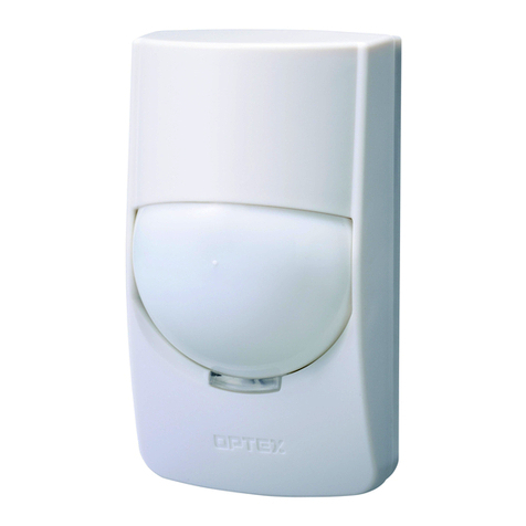
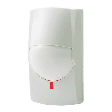
RXC-DT
Deze eenheid is ontworpen om bewegingen van een indringer te
detecteren en een alarmbesturingspaneel te activeren.
Omdat het slechts een onderdeel van een compleet systeem is, zijn wij
niet aansprakelijk voor enige schade of andere gevolgen van een inbraak.
ПРИМЕЧАНИЕ
Это устройство предназначено для обнаружения движения
нарушителя и активации управления сигнализацией.
Это всего лишь часть общей системы, поэтому мы не несем
никакой ответственности за любые повреждения или иные
последствия, причиненные вторжением.
Вес
RXC-DT
RXC-DT
RXC-DT
RXC-DT RXC-DT RXC-DT RXC-DT
RXC-DT
RXC-DT
RXC-DT
22.5°
22.5°
82.2 (3.2)
Mark position provides the maximum detection range.
Caution>>
The using of a mounting bracket may affect the
unit range of detection and dead zone area.
**
När den inkommande spänningen sjunker öppnas larmreläet innan
förlust av känslighet.
Da -20°C a +50°C (Da -10°C a +40°C: IMQ certificato)
UL/c-UL Listed
larm klass 2, miljö klass II, SSF 1014
IMQ-SECURITY SYSTEM
PD6662: 2010
EN 50131-1 Grades and Environmental Class;
Security Grade 2, Environment Class II.
EN 50131-2-4
Tested and certified by Telefication.
We declare the DC power source provided to the product is
DC 9.5~18V and must be limited power source complied
IEC 60950-1 chapter 2.5.
The following table indicates the areas of intended use of the
equipment and any known restrictions. For countries not included
in this list, please consult the responsible Spectrum Management
Agency.
9COMPLIANCE
Conformité
Zur Beachtung
Conformità
Legislativa
Conformidade
Naleving
Conformidad
Kravuppfyllnad
Deklaracja zgodności
Соответствие
Cet appareil est fait pour détecter les mouvements intrus et activer
un panneau d'alarme.
Le détecteur est protégé contre l'immunité au champ magnétique.
N'étant n'est qu'une partie d'un système complet, nous rejetons
toute responsabilité pour tout dommage ou autres conséquences
suite à une intrusion.
FCC ID: DC9 OPMWWL IC: 4012A-OPMWWL
This device complies with Part 15 of the FCC Rules.
Operation is subject to the following two conditions:
(1) This device may not cause harmful interference.
(2) This device must accept any interference
received, including interference that may cause
undesired operation.
10.525 GHz: Belgium, Denmark, Finland, Greece, Italy,
Luxembourg,The Netherlands, Spain, Sweden,
Iceland, Norway,Switzerland
10.587 GHz: France, Ireland, United Kingdom, Belgium,
The Netherlands, Luxembourg
Microwave emission Frequency and Power
EU contact information
Manufacturer:
OPTEX CO., LTD.
5-8-12 Ogoto, Otsu, Shiga, 520-0101 JAPAN
Authorised representative in Europe:
OPTEX (EUROPE) LTD.
/ EMEA HEADQUARTERS
Marandaz House 1 Cordwallis Park, Clivemont Road,
Maidenhead, Berkshire, SL6 7BU U.K.
OPTEX INC. (U.S.)
URL: http://www.optexamerica.com
OPTEX DO BRASIL LTDA. (Brazil)
URL: http://www.optex.net/br/es/sec
OPTEX (EUROPE) LTD. / EMEA HQ (U.K.)
URL: http://www.optex-europe.com
OPTEX TECHNOLOGIES B.V. (The Netherlands)
URL: http://www.optex.eu
OPTEX SECURITY SAS (France)
URL: http://www.optex-security.com
OPTEX SECURITY Sp.z o.o. (Poland)
URL: http://www.optex.com.pl
OPTEX PINNACLE INDIA, PVT., LTD. (India)
URL: http://www.optex.net/in/en/sec
OPTEX KOREA CO.,LTD. (Korea)
URL: http://www.optexkorea.com
OPTEX (DONGGUAN) CO.,LTD.
SHANGHAI OFFICE (China)
URL: http://www.optexchina.com
OPTEX (Thailand) CO., LTD. (Thailand)
URL: http://www.optex.net/th/th
Copyright (C) 2017 OPTEX CO.,LTD.
RXC-DT-X5 : 10.525 GHz 10.4 mW e.i.r.p.
RXC-DT-X8 : 10.587 GHz 14.6 mW e.i.r.p.
Hereby, OPTEX declares that the radio equipment type
RXC-DT-X5 and RXC-DT-X8 are in compliance with
RED 2014/53/EU. The full text of the EU DoC is available
at the following internet address; www.optex.net
Optex RXC-DT shall be supplied by a SELV and LPS (or UL1310
class 2) power supply or connected to a dedicated control unit with
SELV and LPS output.
