manuals.online logo
Brands
  1. Home
  2. •
  3. Brands
  4. •
  5. Rielta
  6. •
  7. Security Sensor
  8. •
  9. Rielta STZ-RK User manual

Rielta STZ-RK User manual

WIRELESS FLOOD
DETECTOR
«STZ-RK»
Installation Guide
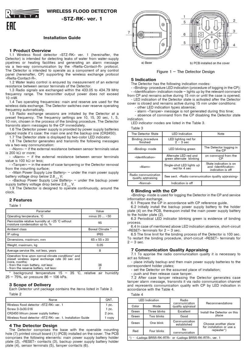
1 Product Overview
1.1 Wireless flood detector «STZ-RK» (hereinafter, the Detector) is intended
for detecting leaks of water, water solutions, other current-conducting
non-aggressive liquids and generating an alarm message via a two-way
communication by the «Rielta-Contact-R» protocol. The Detector is intended to
operate as a component of any control panel (hereinafter, CP) supporting the
wireless exchange protocol «Rielta-Contact-R».
1.2 The Detector comprises a Signal Processing Module (SPM) and flood sensors
«DZ-3V» (FS). The SPM has two connecting blocks for FS hooking up: «G 1» and
«G 2». Not more than two FSs can be hooked up in parallel to each loop.
1.3 The Detector is able to operate in two-loop or single-loop mode. The last
mode presumes the «G 2» status is ignored. The operation mode choosing is
available during the detector logging in the CP.
1.4 Radio signals are exchanged within the 433.05 to 434.79 MHz frequency
range. The transmitter output power does not exceed 10 mW.
1.5 Two operating frequencies: main and reserve are used for the wireless data
exchange. The Detector switches over reserve operating frequency automatically.
1.6 Radio exchange sessions are initiated by the Detector at a preset
frequency. The frequency settings are 10, 15, 30 sec, 1, 5, 10 min, chosen in
the process of the the binding procedure. The SPM transmits alarm messages
to the CP immediately.
1.7 Independent power supply of the Detector is provided by power supply
batteries placed inside it’s case: the main one (CR123A) and the backup one
(CR2450). If the main power supply battery is low, the Detector switches over
to the backup power supply source automatically.
1.8 The Detector generates and transmits the following messages:
- «Norm in Loop 1» – under the absence of liquid between the FS contacts
plugged to «G 1»;
- «Norm in Loop 2» – under the absence of liquid between the FS contacts
plugged to «G 2»;
- «Alarm in Loop 1» – under the presence of liquid between the FS contacts
plugged to «G 1»;
- «Alarm in Loop 2» – under the presence of liquid between the FS contacts
plugged to «G 2»;
- «Tamper» – under the case tampering or SPM removal from the installation
surface;
- «Failure in Loop 1» under the break of communication bus SPM – FS,
hooked to «G 1»;
- «Failure in Loop 2» under the break of communication bus SPM – FS,
hooked to «G 2»;
- «Main Power Supply Low Battery» – under the main power supply battery
voltage drop over 2.2-0.2 V;
- «Backup Power Supply Low Battery» – under the backup power supply
battery voltage drop over 2.2-0.2 V.
1.9 The Detector is designed to operate continuously, around the clock.
1.10 The Detector provides immunity to electromagnetic interference.
1.11 The level of industrial interference generated by the Detector does not
exceed the norms established for the technical equipment operated in residential
buildings or connected to power mains of residential buildings.
2 Features
Table 1
Features Value
Assumed number of FSs in an alarm loop circuit, max 2 pcs.
Length of each alarm loop between the FS and the
SPM, max 5 m
Weight:
- SPM, max
- FS, max
0.1 kg
0.03 kg
Operating temperature minus 20 … +55 °C
Permissible relative humidity at +25 °C temperature up to 98 %
Case dimensions:
SPM, max
FS, max
112 x 41 x 32 mm
65 x 22 x 16 mm
IP rating:
- SPM
- FS
IP30
IP67
Average service life 8 years
Battery life under normal climate conditions and speci-
fied broadcast period not more than 60 sec, not less:
- main power supply battery
- backup power supply battery
60 months
2 months
Figure 2
–
Flood Sensor «DZ-3V»
5 Sound and LED Indication
The Detector has the following indication modes:
-
«
Binding
»
procedure LED indication (procedure of logging in the CP);
- LED indication of the mode
«
Identification
»
– lights up by sending relevant
command from CP and remains active during 15 min or until the case is opened;
- LED indication of the Detector state – lights up and remains unchanged for
15 min after the case is closed under conditions:
- other LED indication types (except the sound alarm) absence;
- alarm
«
Tamper
»
message is not generated during this time period;
- the Detector state indication is ON upon the receipt of relevant command
from the CP.
LED indicator modes are listed in the Тable 3.
Тable 3
The Detector Mode Indication Note
Binding procedure
finished LED lighting red for 2
–
3 sec
«Binding» mode
LED blinking green with
0.25 sec period
The Detector
logging in the CP
in single-channel
mode
LED blinking green with 1 sec
period
The Detector
logging in the CP
in double-channel
mode
«Identification» Alternate LED red and green
alternate blinking
on command from
the CP
«Alarm in Channel 1»
«Alarm in Channel 2»
Single-shot LED lights up red
for 4 sec *
State indication
is on and
«Identification»
indication is off
Generation
«Alarm in Channel 1»
«Alarm in Channel 2»
Sound alarm dual switching **
State sound
indication is on
Fallback recovery
«Alarm in Channel 1»
«Alarm in Channel 2»
Single-shot sound alarm
switching **
Radio communication
quality appraisal See sect. «Radio communication quality appraisal»
3 Scope of Delivery
Each Detector unit package contains the items Table 2.
Table 2
Name Qty
Signal processing module «STZ-RK SPM»
Flood sensor «DZ-3V»
CR123A lithium power supply battery
CR2032 lithium power supply battery
Set of accessories:
Screw 3-3x30.016
Nylon wall plug NAT 5x25 SORMAT
Wireless flood detector «STZ-RK». Installation Guide
1 pc.
2 pcs.
1 pc.
1 pc.
6 pcs.
6 pcs.
1 copy
4 Design of the Detector
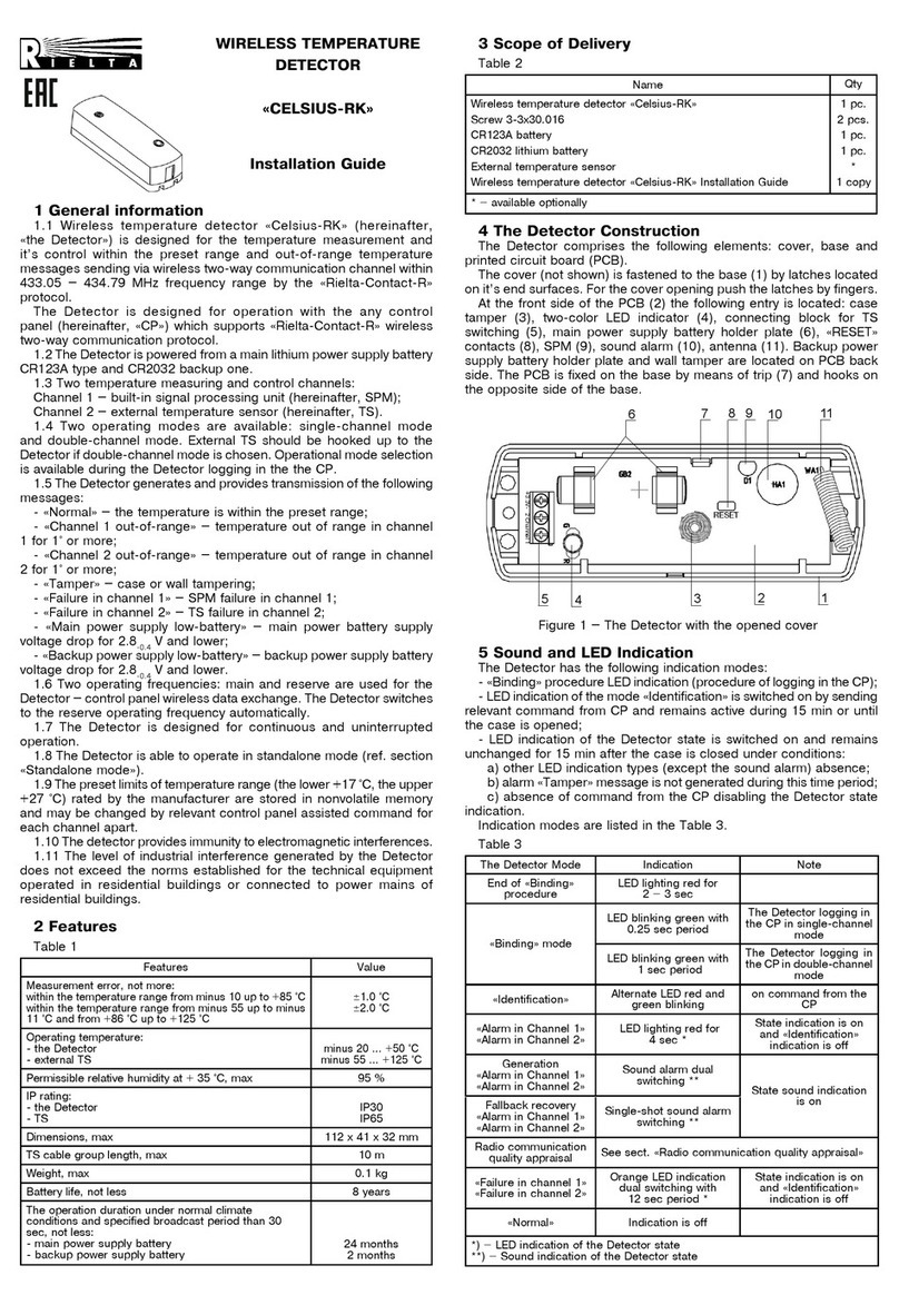
The external appearance of the SPM is shown in Figure 1.
The SPM comprises a base, a cover and a printed circuit board (PCB).
The front side of PCB (1) comprises: tamper (2), LED indicator (3), connec-
ting blocks (4) for connecting the FSs, main power supply battery holder (5)
and backup power supply battery holder (10), «RESET» contacts (7), sounder
(8), antenna (9). The tamper are located on the reverse side of the PCB. The
PCB is fixed in the base of the case by a latch (6) and grips on the reverse
side of the base.
Figure 1
–
The Base with the PCB
The «DZ-3V» layout is shown in Figure 2.
red
black
2 G 1
1
2
38
96
5
4
«DZ-3V»
7
10
red
«DZ-3V»
Reset
●
The case of the FS is watertight, it is
provided with sensing contacts and a
1.5 m cable for connecting to the SPM. The FS
is designed to be fastened to both horizontal and
vertical surfaces.
Table 3, continuation
The Detector Mode Indication Note
«Failure in channel 1»
«Failure in channel 2»
Orange LED indication dual
blinking with 12 sec period *
State indication
is on and
«Identification»
indication is off
«Normal» Indication is off
*) – LED indication of the Detector state
**) – Sound indication of the Detector state
6
Binding with the CP
«
Binding
»
mode is used for logging the Detector in the CP and service
information exchange.
6.1 Prepare the CP in accordance with CP reference guide.
6.2 If it is necessary to log the Detector in double-channel mode, hook up TS
to the Detector as shown in Figure or short-circuit the terminals of the Detector
«
-
»
and
«
G 2
»
. For the single-channel mode neither hooking on, no short-circuit
is required.
6.3 Insert backup battery to the holder plate(10) (if the battery is already set
into the holder, than pull out the insulating foil)
6.4 Insert main battery to the holder plate(5) (if the battery is already set into
the holder, than pull out the insulating foil).
6.5 Periodical LED indicator blinking green is evidence of binding process.
6.6 In case of mentioned above LED indication absence, short-circuit
«
Reset
»
terminals for 2 – 3 sec.
6.7 Successful binding procedure complying is indicated by LED indicator
lighting red for 2 – 3 sec.
6.8 The time limit for the binding process of the Detector is 70 sec. To restart
the binding procedure, short-circuit
«
Reset
»
terminals for 2 – 3 sec.
7
«
Stand Alone
»
mode
7.1 The Detector changes to stand alone mode upon the expiry of 100 sec
binding procedure.
7.2 During operation in the stand alone mode LED and sound indication is
always ON under condition of
«
Tamper
»
message absence.
7.3 The Detector has no communication with CP and its state is displayed
only by means of LED and sound indication (see Table 4).
Table 4
The Detector Mode Indication Period
«Main battery discharge»
«Backup battery discharge»
LED lighting orange for 2 sec
Sound indicator single-shot actuation 12 s
«Alarm in Loop 1»
«Alarm in Loop 2»
LED lighting red for 2 sec
Sound indicator single-shot actuation 4 s
«Failure in Loop 1»
«Failure in Loop 2»
Double-shot LED lighting orange for 2 sec
Sound indicator single-shot actuation 12 s
«Norm» Green LED single-shot blinking 12 s
8 Communication Quality Appraisal
8.1 For radio communication quality appraisal it is necessary to:
- set the Detector on the assumed place of installation;
- push and then release case tamper.
8.2 After case tamper releasing the Detector generates case tamper
alarm message, transmits it via radio communication channel and represents
communication quality with CP by LED indication in accordance with the Table 4.
Table 4
LED Indication Radio
communication
quality appraisal
Recommendations
Color Mode
Green Three
blinks Excellent Install the Detector on
this place
Green Two blinks Good
Green One blink Communication
established Choose another place
for installation or use a
repeater*)
Red Four blinks No communication
*) – «Ladoga-RK» system repeater
9 Installation
9.1 Drill holes for fastening the Detector elements. You may use the FD and
the SPM base without the PCB for marking out the holes.
The FS should be located in the place, where the water spilled in the
detection zone close the sensor contacts. The FS installation with the terminals
downwards ensures generation of alarm signal over appearance the liquid sheet
with a thickness exceeding 1 mm. The FS installation with the terminals sidewise
provides easy access to the sensor terminals for removal of a liquid from the FS
surface between the terminals after the leakage elimination.
9.2 Fasten the FS on the mounting surface with screws or a water-resistant
glue. Fasten the SPM base on the mounting surface with screws. For the wall-
tamper monitoring, the second screw must be screwed in a hole under the wall
tamper. Install the PCB, connect the FSs to the loop terminals (the red wire to
the «+» terminal). Install the cover.
«RIELA» JSC, www.rielta.com,
17 Chapayeva St., Saint Petersburg, Russia, 197101, [email protected],
tel./fax: +7 (812) 233-0302, 703-1360,
Technical support: tel.: +7 (812) 233-29-53, 703-13-57, [email protected]
Made in Russia
Rev. 4 of 19.02.18
№Э00439
v.11.1/ v.12
10 Troubleshooting
Table 5
CP Message Elimination Procedure
«Tamper» Check the security of the SPM fastening, close
it’s cover
«Alarm in Loop 1»
«Alarm in Loop 2»
In case there is no liquid (moisture) between the
FS contacts, check the absence of a short circuit
between the wires
«Failure in Loop 1»
«Failure in Loop 2»
Check the integrity of the wires connecting the
FS and the SPM and their fastening to the SPM
terminals
«Main power supply
battery fault»
Replace the main power supply battery and the
backup one
«Backup power supply
battery fault» Replace the backup power supply battery
11 Manufacturer’s Guarantees
11.1 The manufacturer guarantees conformity of the Detector to the
requirements of technical conditions provided the transportation, storage,
installation and operation conditions are observed.
11.2 The guaranteed shelf life of the Detector is 63 months since the date of
manufacture. The guaranteed useful life is 60 months since the day of putting
into operation within the limits of the guaranteed shelf life.
11.3 The detectors that are found non-conforming to the requirements of the
specifications will be repaired by the manufacturer, provided the installation and
operation rules have been observed.
Note – Warranty obligations do not apply to batteries.
12 Storage and Transportation
12.1
The Detectors are transported without power supply battery. The De-
tector in their original packaging are resistant to:
- transport jolting with the acceleration up to 30 m/sec2at impact frequency
range from 10 to 120 per minute or 15 000 strikes;
- ambient temperature range minus 50 ... +50 °С;
- relative air humidity (95 ± 3) % at a temperature +35 °С.
12.2 The Detector in original package may be transported by any means
of transportation in closed vehicles over any distances in compliance with the
existing shipping rules concerning the respective means of transportation.
13.3 After transportation under the conditions different to exploitation
conditions the Detector shall be ready to operate after a maximum of six hours.
14.4 The storage room shall be free from current-conducting dust, acid va-
pors, alkali and gases that cause corrosion and destroy insulation.
13 Packing Certificate
Wireless flood sensor «STZ-RK» manufactured in accordance with current
technical documentation is classified as fit for operation and is packed by
«RIELTA» JSC.
Packing date _______________________________
month, year
Figure 3 - SPM base
9.3 Fasten the FS on the mounting surface
with screws or a water-resistant glue. Fasten
the SPM base on the mounting surface with
screws. To ensure the wall-tamper control,
the second screw must be screwed in the wall
tamper fixing arm. Install the PCB, connect
the FSs to the loop terminals in accordance
with the Figure 1 . Install the cover.
ATTENTION! Antenna should be installed
into the holder (see Figure 3). Antenna
installation outside of the holder essentially
reduces communication range.
Fixation holes for
fastening base to
mounting surface
Antenna holder
Wall tamper fixing
arm
Other Rielta Security Sensor manuals

Rielta FOTON-15A User manual

Rielta

Rielta FOTON-15A User manual

Rielta Pyrone-7i User manual

Rielta

Rielta Pyrone-7i User manual

Rielta FOTON-21 User manual

Rielta

Rielta FOTON-21 User manual

Rielta C.Nord CN-Flood-Mini User manual

Rielta

Rielta C.Nord CN-Flood-Mini User manual

Rielta FOTON-17 User manual

Rielta

Rielta FOTON-17 User manual

Rielta FOTON-12-RK User manual

Rielta

Rielta FOTON-12-RK User manual

Rielta Ladoga MK-RK User manual

Rielta

Rielta Ladoga MK-RK User manual

Rielta FOTON-16B User manual

Rielta

Rielta FOTON-16B User manual

Rielta ORLAN-D User manual

Rielta

Rielta ORLAN-D User manual

Rielta STZ-RK User manual

Rielta

Rielta STZ-RK User manual

Rielta FOTON-SH1 User manual

Rielta

Rielta FOTON-SH1 User manual

Rielta Ladoga MK-RK version 2 User manual

Rielta

Rielta Ladoga MK-RK version 2 User manual

Rielta C.Nord CN-PIR User manual

Rielta

Rielta C.Nord CN-PIR User manual

Rielta STEKLO-3RK User manual

Rielta

Rielta STEKLO-3RK User manual

Rielta ORLAN-2 User manual

Rielta

Rielta ORLAN-2 User manual

Rielta STZ-RK User manual

Rielta

Rielta STZ-RK User manual

Rielta CELSIUS-RK User manual

Rielta

Rielta CELSIUS-RK User manual

Rielta C.Nord CN-Glass User manual

Rielta

Rielta C.Nord CN-Glass User manual

Rielta Pyrone-4D User manual

Rielta

Rielta Pyrone-4D User manual

Rielta PYRONE-5 User manual

Rielta

Rielta PYRONE-5 User manual

Rielta PYRONE-8B-RK User manual

Rielta

Rielta PYRONE-8B-RK User manual

Rielta STZ-RK User manual

Rielta

Rielta STZ-RK User manual

Rielta CELSIUS-RK User manual

Rielta

Rielta CELSIUS-RK User manual

Rielta Ochrana ORLAN-D User manual

Rielta

Rielta Ochrana ORLAN-D User manual

Popular Security Sensor manuals by other brands

MSA Dyna-Glide User instructions

MSA

MSA Dyna-Glide User instructions

iRay Technology Mars1417V user manual

iRay Technology

iRay Technology Mars1417V user manual

Interlogix ACL870SU-BSMF installation manual

Interlogix

Interlogix ACL870SU-BSMF installation manual

Capital Safety DBI-Sala Ultra-Lok RSQ 3504553 Specific instructions

Capital Safety

Capital Safety DBI-Sala Ultra-Lok RSQ 3504553 Specific instructions

GJD D-TECT R Ricochet GJD830R manual

GJD

GJD D-TECT R Ricochet GJD830R manual

Greenlee GT-11 instruction manual

Greenlee

Greenlee GT-11 instruction manual

Hansen Technologies WLT Specifications, Applications, Service Instructions & Parts

Hansen Technologies

Hansen Technologies WLT Specifications, Applications, Service Instructions & Parts

rollease acmeda AUTOMATE ARC Motion Sensor instructions

rollease acmeda

rollease acmeda AUTOMATE ARC Motion Sensor instructions

Titanium TT-ACC-IR-11 manual

Titanium

Titanium TT-ACC-IR-11 manual

pdlux PD-MV1005-Z instructions

pdlux

pdlux PD-MV1005-Z instructions

Sygonix 1593961 operating instructions

Sygonix

Sygonix 1593961 operating instructions

Adixen ASM 142 D user manual

Adixen

Adixen ASM 142 D user manual

Baumer FZAM 18P6460 quick start guide

Baumer

Baumer FZAM 18P6460 quick start guide

Honeywell FF-SPS4 Series installation manual

Honeywell

Honeywell FF-SPS4 Series installation manual

DINUY RE DMS 001 instruction manual

DINUY

DINUY RE DMS 001 instruction manual

Qazqa Rana WL PIR LUX LED Solar instruction manual

Qazqa

Qazqa Rana WL PIR LUX LED Solar instruction manual

Smartwares SMA-40151 instruction manual

Smartwares

Smartwares SMA-40151 instruction manual

ADT TMD15 user guide

ADT

ADT TMD15 user guide

manuals.online logo
manuals.online logoBrands
  • About & Mission
  • Contact us
  • Privacy Policy
  • Terms and Conditions

Copyright 2025 Manuals.Online. All Rights Reserved.