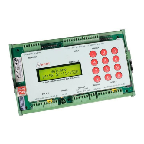
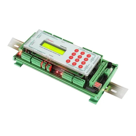
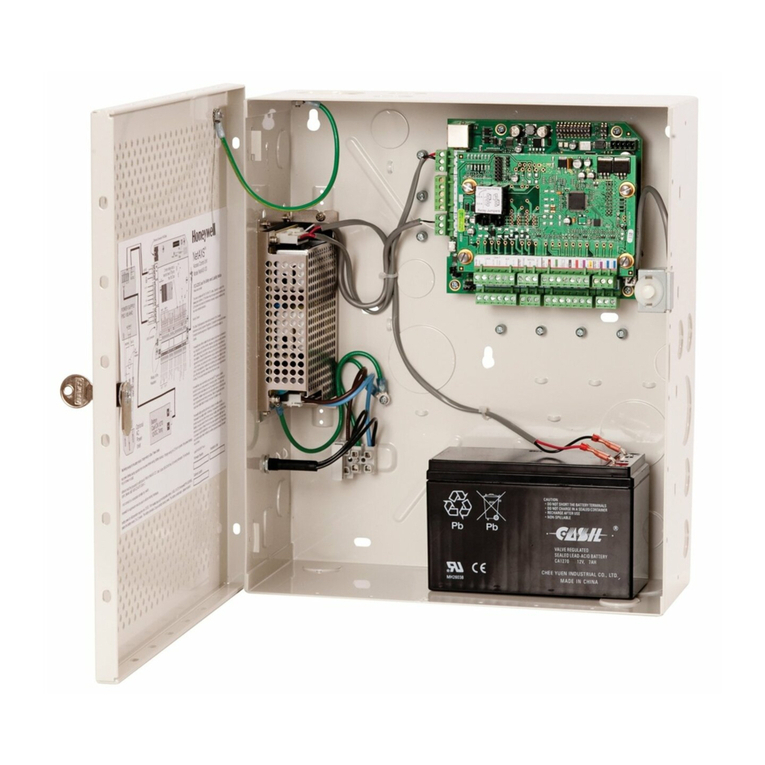
Smarti SMNG240 User manual

Smart-iELECTRONICS SYSTEMS PVT. LTD.(An ISO 9001:2008 certified company)
Tel: + 91-22-6566 6555
Web site:
www.smartisystems.com

2
Contents
PRODUCT SELECTION ............................................................................................................... 4
INTRODUCTION .......................................................................................................................... 4
SPECIFICATION ........................................................................................................................... 5
Hardware specification:............................................................................................................... 5
Access control features:............................................................................................................... 5
KEYPAD DETAILS....................................................................................................................... 6
NG 2DR4RD CONNECTION DETAILS: ................................................................................... 10
DEVICE CONFIGURATION ...................................................................................................... 12
RECOMMENDED CABLE SPECIFICATION........................................................................... 13
CONNECTING TO HOST COMPUTER USING ....................................................................... 13

3
WARNING & CAUTION
ØPlease handle the equipment with care. Physical Damage to the system is not covered under
warranty.
ØDo not power on the system without reading this manual. Ensure proper power supply with
Earthing.
ØNote down the serial number and model no. of the device for future reference and quote in all
support and service requests.
ØTo connect or interface the Card reader to the Smart XS NG unit please refer to the Hardware
nstallation Guide or Manual and carefully follow the instructions. A trained technician must
make the connections.
Any negligence on your part may damage the Card reader interface on the Smart XS NG
terminal.
ØDo not use this unit near water.
Ø Do not open system or places it near other heavy electrical equipment. The system is sensitive
to Electro Static Discharge (ESD)
ØNever insert objects of any kind into the unit or through the cabinet slots as they may touch
voltage points and/or short circuit parts possibly resulting in fire or electric shock. Never spill
liquid of any kind on the unit.
ØWhen connecting up the Controller Access Controller ensure that the mains power supply is
safely isolated. Power up the controller only when installation is complete.
ØOperating conditions: 0 to 55 deg Celsius and 50 deg Celsius at 90% RH.
Fire Safety and accountabi ity Notice
When connecting card or Biometric readers to any emergency entry, exit door, barrier or elevator must
provide an alternative exit in accordance with all fire and life safety codes pertinent to the installation.
These fire and safety codes vary from city to city and you must get approval from local fire officials
whenever using an electronic product to control a door or other barrier.
Important Instructions
Care should be taken identifying the wires. mproper wiring may render permanent damage to
the device or personal injury.
Refer the color code on the Reader to connect the external weigand reader on the controller.
Check the earthing at the site before installing the controllers. Normally the earthing should be
between 1V to 2V only. Earthing on the higher side may damage the controller or its various
other components.
Before nstallation delete all data (Factory reset) using keypad menu * 90
Disc aimer
Changing of default user password is mandatory to avoid tampering of the device.
n case of user password not changed; smart will not be responsible for any tampering on the
device.

4
PRODUCT SELECTION
Particulars Specifications
Model no. SMNG240
Applications Access Control
INTRODUCTION
The
new NG SMART 2door 4reader blends loads of innovative features to streamline
installation and administration for large business enterprises for multiple doors access
control deployment. NG 2dr4rd brings the high speed, accuracy, flexibility and user
friendly interactivity.

SPECIFICATION
Hardware specification:
Particulars Description
CPU 32 Bit RISC Arm
Memory Flash 4MB
Events/Transactions 60,000
No. of Users 30000
Operation Modes Card Only, (On Weigand Card Only).
Card Reader Options
(extra Module) Mifare, HID (I Class), HID Prox, EM cards.
Communications Port TCP/IP, RS485
Baud Rate 9600bps (Default)
Controller ID Max 9999
LCD 16x2
Keypad Dome keypad
Language English
Power Supply 12 V DC/ 5A (Min)
Enclosure Metal
Color / Weight Siemens grey
Dimension (L X H X D)
in mm L= 370mm X W=325mm X D=75 mm
Mounting Wall Mounting
Access contro features:
Particulars Description
Facility Code Available
Time Zone /
Access Levels
63 + 1 (Free Time Zone)/128
Time Zone Slots 4 slots per Day
Anti-Pass back Hard, Soft, Escort (Reader Wise)
Holiday Settings 42

KEYPAD DETAILS
Sr. No. Function How to go? Note Observation
(IDEAL)
1)
Normal mode Key – *0 In this mode card is shown
2)
Admin Mode Key – *2
Enter User ID – 11111
Key – #
Enter Password – 12345
Key – #
To log out from Admin mode
press
Key – *2
Key – #
(Auto logoff after 60sec)
3)
Add User Key – *3
Show card
Key – #
After showing card to reader 1,
card no will come
automatically on LCD then
press #
4)
Delete User Key – *4
Show card
Key – #
After showing card to reader 1,
press #. Then that user gets
deleted.
5)
Search User Key – *5
Show card
Key – #
If user is added then it will
show card no with password.
6)
Set Time & Date
Key – *6
Enter Time/Date
Key – #
Enter correct Date & Time.
7)
Help Menu Key – *8
Press – 1 for INC
Press – 3 for DEC
Press – # to enter
We can directly go in to any
menu by pressing “#” key.
8)
Initialize system Key – *90
Press – 1 for INC
Press – 3 for DEC
Key – # to enter
00 Delete all data
01 Delete Transaction
02 Delete All Users
03 Set All Default
04 Delete Sys. Info
05 Delete Time Zone
06 Delete Holiday
07 Delete Facility Code
08 Delete Door info
09 Delete Admin IDs
10 Reset System
11 Delete Cards Only
Refer
Annexure:1
9)
Controller Slave
ID
Key – *91
Enter Controller Slave
ID
Key – #
By default it is set to 1.
We can assign controller ID
from 1 to 128.
10)
Add / Change or
Delete Admin
Users
Key – *92
Press – 1 for Add/Ch
Press – 3 for Del
We can add max 16 admin
users (0 – 65535nos)including
default admin user (i.e. User

Key – #
Enter user ID then #
Enter password
Key – #
ID = 11111 and Password =
12345)
11)
Door open time Key – *94
Enter door open time
Key – #
Door open time can be set for
all doors 1 to 98 secs.
And DOTL sense time is equal
to Door open time + 1 sec.
12)
Facility code Key – *96
Press – 1 for Enable
Press – 3 for Disable
Press – # #
Enter Facility code
location (0-7)
Show card
Key – #
After pressing 1, Enter facility
code location & show card.
Then facility code will come
automatically for that card.
Max 8 facility codes can be
assigned.
13)
Set Controller
Type
Key – *97
Then select controller type
for reader 1 by selection
keys from 1 to 8, and then
press # key. Same way set
controller type for reader 2
to 4 same as above.
1 = Weigand Access
3 = Weigand Att.
5 = Weigand Att. No check
6 = Deny list
14)
Set IP Address Key – *990
Enter Unit IP Address
Press – #
Enter Subnet mask
Press – #
Enter Default gateway
Press – #
Enter Server IP
Address
Press – #
Enter Port No.
Press – #
We can set Unit IP, Subnet
mask, Default gateway, Server
IP, Port No. using this menu.
After setting all parameters
reset the system to take
effect.
15)
Display Current
System
Parameters
Key – *991
Press Enter key to get
next data
System parameters: -
Terminal ID
IP Address
Net Mask
Gateway
Server IP
Port Number
Global Msg
Banner Msg
ContInOut
Identify Mode

Controller Type
User name loc
Memory mgmt , etc.
16)
Set 5/8/10 Digit
card no format
Key – *995
Press – 5 for 5-Digit
Press – 8 for 8-Digit
Press – Any Num Key
except 5 & 8 for 10-Digit
Key – #
After setting card format to 5-
Digit it will display and
process 5-Digit card no.
And for 10-Digit format, it
will display and process 10-
Digit Card no.
For 8 digit card no it will
display 5 digit card no & 3
digit facility code.
Refer note
17)
Controller No Key – *996
Enter Controller No to
be set
Key – #
We can set unique controller
no (0 - 9999) using this menu.
18)
System Info Key-*9991
Press enter key to get next
data
Model Number
Unit ID
Controller No
Card Buffer
Used Card Buffer
Bal. Card Buffer
Trans Buffer
Used Trans Buff
Bal Trans Buff
Serial No
Manufacturing Date
FW Compile Date
Firmware Version
Hardware Version
Controller Type
Reader Type
MAC address
19)
Bulk Add card Key-*9993
Press – 1 for add cards
Press – 3 for delete cards
For card addition &deletion
only show card, it will
automatically get added or
delete from controller.
20)
Fire/Tamper Key – *9994
Use Keys 0, 1, 2 or 3 to
enable disable fire &
tamper.
Then press #
To enable disable fire &
Tamper press following keys,
0 = Disable All
1 = Enable Fire
2 = Enable Tamper
3 = Enable Fire Tamper
4 = Enable Intrusion
5 = Enable Fire and Intrusion
6 = Enable Intrusion and
1 = Enable Fire

Tamper
7 = Enable All
21)
Weigand Card
Data
Key- *9998
Show card on any reader
To get received card no, its
bit etc. from particular reader.
22)
Network Ping Key- *99990
Network ping
To Ping Network
1= Ping gateway
2= Ping Internet
23)
Enable/Disable
DIS
Key – *99991
Press – 1 for Enable
Press – 3 for Disable
Door interlock system used to
control entry from secure
areas. Need to set DIS group
by s/w.
Note:
1. A add user, de user, …. Functions (3 to 24) are done in Admin mode.
2. Auto Logoff for Admin after 60 secs. (If any key is not pressed)
3. If system is initia ized or IP address is set then reset the system.
4. For 26 bit reader you can set *995 keypad menu to 5 digit, 8 digit &10 digit card as
per requirement.
5. For 32, 34 & 35 bit reader set *995 keypad menu to 5 digit &10 digit on y.
Annexure: 1
*90 Se ective Initia ization of System
00 Delete all data Every nfo is deleted and set to default value
01 Delete Transaction All transaction are deleted
02 Delete All Users All users i.e. card buffer are deleted
03 Set All Default
Deletes all info and set it to default value, except card buffer and
transactions
04 Delete Sys. nfo Deletes current system parameter and set all with default system
parameter
05 Delete Time Zone Deletes all time zones and set default time zone
06 Delete Holiday Deletes all holidays
07 Delete Facility Code Facility codes are deleted and all are set to default Facility code
08 Delete Door info Deletes door information and set to default Door information
09 Delete Admin Ds Admin d is deleted and set to default D
10 Reset System Resets the system
11 Delete Cards Only Only card buffer is deleted

NG 2DR4RD CONNECTION DETAILS:
J13
J9 J23
J
7
J8
J
24
F+
F
-
I+
I
-
12V
G
D0
D1
BZ
LED
TAMP
12V
GND
GNDL
12VL
GND
D+
D
-
TAMPER
Ether et
J19
12V
G
D0
D1
BZ
LED
TAMP
Reader 1 Reader 4
Digital supply
Lock supply
RS485
Door 2
Door 1
Fire pa el
I trusio
J20
12V
G
D0
D1
BZ
LED
TAMP
Reader 2
J21
12V
G
D0
D1
BZ
LED
TAMP
Reader 3
BZ
-
C
NC
NO
EG+
EG
-
MC
-
BZ+
GD
MC
+
BZ
-
C
NC
NO
EG+
EG
-
MC
-
BZ+
GD
MC
+
J14
JP1
JP2
JP3
Lock supply

11
Co ector Details:
Power supply (J7):
Sr. no
Signal
1.
GND
2.
12V
Door Lock co ectio (1 & 2):
Sr. no
Signal
1.
C
2.
NC
3.
NO
4.
GND
Door Co ectio (1 & 2):
Sr. no
Signal
1.
EG+
2.
EG
-
3.
MC +
4.
MC
-
5.
BZ+
6.
BZ
-
EML co ectio for all doors:
Lock Supply co ectio (J8):
Sr. no
Signal
1.
GND
2.
12V
Weiga d Readers co ectio (1 to 4):
Sr. no
Signal
1.
12V
2.
GND
3.
D0
4.
D1
5.
BZ
6.
LED
7.
MP
Strike locks co ectio for all doors:
C
NC
NO
+
-
GL
C
NC
NO
+
-
Strike
latch
J8
GND
12V
-
GL
12V
GD
J8


13
RECOMMENDED CABLE SPECIFICATION
Distance Cab e Specs
Access controller to Weigand
reader
Up to 80mtr 14/36, 22AWG, 6 core shielded cable
Egress /Exit Up to 80mtr 7/38, 22AWG, 2 core cable
Magnetic contact Up to 80mtr 7/38, 22AWG, 2 core cable
Magnetic Lock Up to 80mtr 14/36, 22AWG, 2 core cable
CONNECTING TO HOST COMPUTER USING
The NG Can be Connected to the computer by TCP/IP (Ethernet).
Note: Use proper manually crimp CAT5 cable, Refer bellow images,
Manually Crimped RJ-45 ReadymadeRJ-45
X
Other Smarti IP Access Controllers manuals
