Smartreefs Tosta-PRO User manual

System connection -----------
Installation Notes -----------
Instruction for A.T.O. --------
Instruction for A.W.C. --------
Advanced settings --------
Instructions for use --------
Child lock and others --------
Show code meaning ---------
Troubleshooting ----------
P1
P2-3
P4
P6-P8
P8-P14
P15
P16
P17
P18
Manual
Auto water changer
(Pro version)
Ver.1.0

System connection [Universal]
1
An anti-siphon
Installation Notes
2
3
4
1
12
An anti-siphon
An anti-siphon
· The anti-siphon device needs to be installed in
the fish tank. There is no difference in direction
between the two small heads on the device, but
the large head needs to be higher than the water
surface and lower than the edge of the glass. .
· If the water level in the bucket is higher
than the water level in the area where
the main controller is installed, an
anti-siphon device should also be installed
above the pump in the bucket.
· An anti-siphon device must be installed
above the drainage pump, otherwise non-
stop drainage may occur;
An anti-siphon · If it is not in the process of changing water, such
as when the circulating pump is stopped, at this
time,if the water level is higher than the siphon
prevention device, no siphon phenomenon will
occur.
Installation of
the host
· The main control has a water level detection
device, so the main control needs to be installed
in the transparent glass to work properly;
Please check the connection method:
Appendix 1: Sea water,water source are buckets
Appendix 2: Seawater, A.T.O. source is water purifier

Installation and A.T.O.function
1
2
3
1
34
Installation
steps
2. Connect the water inlet device to the green
connector and the drain pump to the black
connector;Connect the temperature probe to
the black audio connector.
1. Install the host on the section where the
water level in the fish tank can change, and
make the current water level near the "LOW"
water level line.
· You can use a PE pipe(DN10)(commonly used
for RO water purifiers) to extend the water
inlet and outlet pipes, and you can directly put
the hose on a rigid pipe (at least 5cm is
appropriate).
4. Fill the bucket with water.
3. Install anti-siphon device and water pipe
according to the figure.
1. Turn on the power, and then press the three
buttons at the same time. After 5 seconds, the
system will emit a beep sound. At this time, you
can release the buttons.
2
3
4
1
· The installation site must be cleaned before
installation. Large algae or dirt may cause
abnormal sensing.
· Please note that the internal and external
modules must be aligned, otherwise they cannot
be sensed normally.
Water pipe
· Back filter is usually opaque. After cutting the
black opaque film on the glass with a knife, the
device can be used normally.
2
Water pipe
· The water outlet of the water inlet pipe must be
higher than the water surface, otherwise the
water in the fish tank may flow back to the
bucket.
Installation of
the host
Installation of
the host
Installation of
the host
Installation
steps
Installation
steps
Initialization
2
2. The system will automatically add water to the
vicinity of the MID water level line, then the
system and ATO function are automatically
initialized.
Initialization

Installation and A.W.C.function
1
1
2
1
56
Precautions
· AWC introduction: Automatic replacement of
old and new water for the fish tank according to
the specified water exchange volume and · If
you do not specify an automatic water change
cycle, you can only start a water change task by
manually clicking the AWC button.
· If the water level drops quickly after
exceeding the HIGH level line, there may be
water droplets remaining on the sensor
head, which may cause a false alarm that the
water level is too high. You can take out the
internal module and shake it gently to
remove the water droplets.
· One-key top-up: If the water level is lower
than the LOW level when the A.T.O.
function is paused, short press the A.T.O.
button to start one-key top-up.
· If you do not specify an automatic water change
cycle, you can only start a water change task by
manually clicking the AWC button.
· Clicking any button during the water change will
stop the water change.
1. Perform automatic calibration.
2.Test the water change function
3.Set the water exchange volume.
5. Other setting items (optional).
4.Set the water change interval
1
2
3
1
· The A.T.O. function is automatically suspended
during the automatic water change.
· Briefly press the A.T.O. button to manually
perform a quantitative water addition.
· You can use the setting function to reset the
water volume for a single water fill action.
Advanced
A.T.O.
2
· Pause A.T.O .: If you do not want the A.T.O.
function to be performed, press the Pause
button briefly; press the button again to
resume the A.T.O. function.
Interface
introduction
2
· The significance of automatic calibration:
Because the size of the fish tank is different for
each user, the calibration function allows the
equipment to scan and calculate the fish tank in
order to accurately provide automatic water
change services.
Features
A.T.O.
Features
A.T.O.
Advanced
A.T.O.
Features
A.W.C.
Features
A.W.C.
Steps for usage
Calibration
A.T.O. introduction: It can automatically maintain
the water level between the MID and LOW water
level to prevent the situation of low water level
caused by evaplinesoration.
· With temperature function on standby: Time
and temperature are displayed alternately.
· During standby: The current time is displayed
and can be changed in settings.
· When adding water: Countdown. Water will
not stop until the countdown ends.

7
1
2
3
7
· Click the "AWC" button to change the water
once with the default settings:
Water change: 10 liters.
Operating mode: Simultaneous
8. Calibration will be completed automatically
and return to the standby interface.
5. After the container is full, press the Set
button again.
6. Enter the approximate capacity of the
container in ML.
· The value on the screen represents the
amount of water that has been changed. The
water change task is ended when the set
amount of water is reached.
3
4
1. Press and hold the Set button for 5 seconds to
enter the setting mode, and F1 is displayed on
the screen.
2. Press the Set button again to display F1S1.
5
3. Prepare a container under the water outlet
of the water inlet pipe.
4. Press the Set button again, and the system
starts to pour water into the container.
4
· If the water change is successfully completed,
you can further personalize the automatic water
change according to the following instructions.
Setup
calibration
6
7. Press the SET button again, the system
starts to automatically enter and exit the
water, and the progress is displayed on the
screen as a percentage.
Test run
· Click any button during the water change
process to terminate the water change task.
8
Test run
Setup
calibration
Setup
calibration
Setup
calibration
Setup
calibration
Test run
Test run
Test run
· During calibration, the system will add water
first, then drain water, and finally enter and
exit the water for a period of time. If you find
that neither water is added nor drained,
please check the water source and water inlet
and outlet equipment.
8
Notice

4
5
6
· You can set the required water change interval
days in units of days. For example, if you set the
parameter to 01, the device will automatically
change water once a day.
· Project location: F1S4-B-XX
· Effective the day after the setting is completed.
· Project location: F1S4-A-XXXX
· You can set the required interval for
changing the water in minutes. For example, if
you set this parameter to 60, it means
changing the water every hour.
· Project location: F1S3
· ATO and AWC buttons can increase or
decrease the value,
· You can arbitrarily set the required
amount of single water change.
· Setting range is 1-9999, the unit is liter
· Effective the day after the setting is completed.
· You can specify the exact time when water
change starts. For example, 12:30 means start the
scheduled water change task at 12:30.
· Project location: F1S4-B-XX-XX: XX
1
2
1
· Press and hold the Set button for 5 seconds to
enter the setting mode. At this time, you can
switch between categories (F) by clicking the ATO
or AWC button.
· When F1 is displayed on the screen, press the
Set button again to display F1S1. At this time,
you can switch between various settings (S1-S6)
by clicking the ATO or AWC button.
2
· Project location: F1S2
· Option A: Simultaneous water inlet and
outlet mode
· Default: A
· Option B: Drain first, then water
8
· If you make the above settings correctly, the
system can run fully automatically in the way you
specify. The device also provides other advanced
functions. Please set as needed.
Summary
3
Cycle
· Option B: Change the water interval in days.
· Project location: F1S4
· Option A: Intermittent water change in minutes
· Default: B
Intermittent
Interval
10
Switch
category
Run mode
Volume
Time
7
· Project location: F4S1
· Set the correct current time for the system,
so that the automatic water change task can
be performed accurately at the time you set.
System
clock
Advanced settings (recommended)
9
Switch
settings

· Parameter description: The safety
program in the system will memorize the
water inlet and outlet speed during
calibration. During the water change task,
if the inlet and outlet speed changes a lot,
it may cause a timeout alarm.
1
2
3
· Project location: F1S5
Option On: Turn on temperature linkage during
water change
· Default: Off
Option Off: Disable temperature linkage during
water change
· You can set the minimum temperature limit when
changing water. The system will be suspended
below this temperature, and the process will
resume automatically when the temperature
recovers and 1 ° above this set value.
· Project location: F1S5-On-LXXX
4
· Project location: F1S5-On-HXXX
· You can set the maximum temperature limit when
changing water. The system will be suspended
above this temperature, and the process will
resume automatically when the temperature is
restored and 1 ° below this set value.
Low limit
Timeout
parameter
Temperature
linkage
Advanced settings (optional) [S1 -AWC]
Hight limit
5
Increasing the value of this parameter can
increase the system's response to water inlet
and outlet Tolerance of speed change.
11
Timeout
parameter
6
1
2
3
· Project location: F2S1
· After entering this setting, the system starts
to add water, please press the set button again
when the water level rises about 5-7MM to
end the setting. From now on,A.T.O. function
will raise the water level by 5-7MM each time.
· Project location: F1S6-XXX
· Modify tolerance in order: water in, water
out, and simultaneously.
· Default: 200% / 100% / 150%
· Do not modify this item unless necessary.
· It can set the maximum running times of
A.T.O. function within 24 hours. Once this
number is exceeded, the system will
automatically stop and alarm.
· Project location: F2S3-XXX
· Default: 50 times
4
· Click the Pause button during standby to pause
the ATO function. At this time, if the water level is
lowered below the LOW sensing point, the water
level will not be automatically restored. You can
click the ATO button to start one-key top-up at a
time. There is no time limit for the top-up process.
Set the amount
of A.T.O.
· This function is used to prevent the pump from
running dry when water is scarce. If the number of
consecutive water additions exceeds the value
while the A.T.O. function is running and the water
level is still too low, the system will stop the alarm.
· Project location: F2S3-XX
12
Advanced settings (optional) [S2 -A.T.O.]
Limit on the
number of runs
Limits on the
number of
failures
One-click
top up
Timeout
parameter
· Project positioning: F3S2-HXXX
· The maximum temperature that can be
detected can be set. If the temperature is higher
than this, the system will beep after 5 minutes.
Automatically dismiss the alarm when the
temperature returns to normal.
5
1
2
· Select this function when the water level is lower
than the Low water level, the system will
automatically rise water to the LOW water level,
and use this time as the timeout protection time
of the one-click full function of daily operation.
· Project location: F2S4
· You can set the maximum running protection
time for one-key full function.
· Plugging or unplugging the temperature probe
under power may cause equipment damage.
· The temperature probe is not hot-swappable
· Temperature probe must be inserted when
power is off.
3
· Option On: Enable temperature monitoring
· Option Off: Disable temperature
monitoring
· Project location: F3S1-XX
· Default: Off
4
Low limit
· Project location: F3S3-HXXX
· It can set the minimum temperature that can
be detected. Below this temperature, the
system will beep after 5 minutes.
· The alarm will be automatically cancelled
when the temperature returns to normal.
One-click
top up
protection
Function switch
High limit
Advanced settings (optional) [S2 -TEMP.]
13
Precautions
1
2
3
4
· Option Off: Disable beep alert on anomalies
· Project positioning: F4S2
· Option On: Beep alert when abnormal
· Default: Off
· Set the correct current time for the system,
so that the automatic water change task can
be performed accurately at the time you set.
· Project location: F4S1
· Project location: F4S3-XX.X
· The temperature compensation value can be
set. The system will superimpose this value
on the detection result as the final
temperature detection result.
5
· Selecting this item will restore the system to
factory settings. The effect is equivalent to pressing
3 buttons at the same time to restore the factory
settings.
· Project location: F4S4
Beep settings
· Project location: F4S3-XX.X-X
· Option C: Use ° C as the temperature unit
· Option F: Use ° F as the temperature unit
· Default value: ° F
Advanced settings (optional) [S4 -SYSTEM]
Temperature
compensation
Temperature
unit
Restore
Factory
System time
14

· If you choose the simultaneous water inlet
and outlet mode, the water change will not end
immediately when the water change amount
reaches the predetermined value. The system
will automatically adjust the water level to the
middle of the MID and LOW sensing points, and
then return to the standby interface.
1
2
3
· During calibration, as long as the inlet and outlet
pumps are working properly and the water level is
not lower than the low induction line or higher
than the high induction line, it is normal.
· The larger the fish tank, the closer the speed of
water entering and exiting, the longer it takes,
even more than half an hour.
· When the water level is too high (higher than HIG),
or low (below Low), the water change cannot be
started.
The amount of water used in the water level
adjustment and pump check process is not included
in the total water exchange volumeexchange.
4
· After the water change is started, the water
will be automatically drained below the LOW
sensor line, and then a small amount of water
will be introduced until the water level is
normal. This process is used to determine that
the water inlet and outlet channels are normal.
Calibration
related
Pump
check
Level
adjustment
Instructions for use [related to A.W.C.]
Operational
restrictions
1
2
· ATO indicator: always on when running, off
when standby
· Pause indicator: always on when standby,
flashing when paused
· AWC indicator: off when standby, always on
when changing water
· The water level indicator flashes for 2
seconds after it is on for 2 seconds, please
change the installation position to avoid
direct sunlight.
· If the indicator light is on and the water level
is low, realign the inner and outer modules.
Running
instructions
Instructions for use [indicator]
Water level
indication
1. Press and hold the ATO and AWC buttons
simultaneously for 5 seconds and then
release the buttons.
1
2
Child lock
2. The indicators under all keys are off, and
clicking any button will not trigger the
corresponding function (but there will be a
key feedback sound and light.
Child lock
Child lock and other functions
3
3. Press and hold the ATO and AWC buttons
simultaneously for 5 seconds to release the
lock state.
Child lock
15 16

· AC: Automatically calculate the water supply.
· Err: Run overtime, check make-up water
source and pump / solenoid valve
· Ove: the number of times exceeds the limit,
check that the outlet pipe cannot be lower
than the water surface
1
2
· Pau: The system is paused. Press the Set
button to release the pause.
· ERP: The circuit is abnormal. Please replace
the water pump or solenoid valve.
· SHiG: The water level is too high for more
than 20 minutes.
Hardware
related
A.T.O.Related
3
4
Done: automatic calibration is complete.
· Star: Water is being poured into the container
· Hig: The water level is too high when starting
the water change. Please lower the water level.
· Oro: Drain timeout, please check the drain
pump
· Iro: water inlet timeout, please check the
water inlet device
5
· Aro: simultaneous water inlet and outlet
timeout, please check the water inlet and
outlet device.
If there are no hardware issues, try
running the device calibration again.
Timeout related
4
5
· The alarm will be automatically cancelled
when the water level returns to normal.
· The buzzer alarm will be triggered when the
water level reaches the HIGH level.
· In order to prevent false alarms due to the need
to stop the pump for feeding, the buzzer alarm
will only be triggered if the water level is too high
for more than 20 minutes.
Level
monitoring
Level
monitoring
Show code meaning
A.W.C.Related
Timeout related
17 18

19 20
Troubleshooting suggestions
· If the peripherals are working normally,
but the problem is not resolved,Please re-
initialize the device and run the device
calibration again.
2
3
A.W.C. fault
A.W.C. fault
1
A.T.O. fault
4
· It is usually caused by the failure of the
water source or water inlet and outlet
components. Please check the water source
and observe the water pump or solenoid
valve) when changing the water, then replace
the faulty equipment.
A.W.C. fault
· It is usually caused by water shortage or pump
failure. Please check the water source. If the
pump does not work, please replace the pump.
· If the water level is still too low after three
consecutive water refills, an A.T.O. overtime
alarm will be triggered.
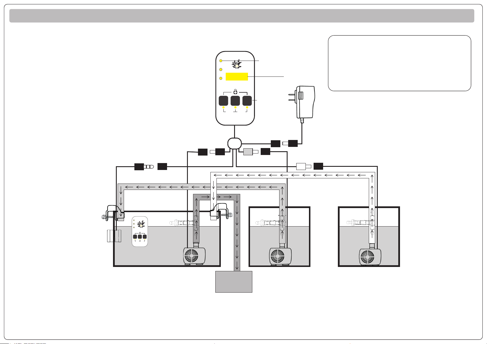
Appendix 1:System connection [Sea water,water source are buckets]
Note: If the water pipe is too long or the water pipe needs to climb the wall, please purchase a high-lift
pump and power extension cable from the dealer to achieve water in and out at a long distance.
↓ ↓ ↓ ↓ ↓
HIG
MID
LOW
A.T.O.
A.W.C .
Fre q.
Sm art re efs
AUTO WAT ER CHAN GER
Buz zer
Pau se
*
HI G
MI D
LO W
A.T.O.
A.W.C.
Q.L.
Sm ar tr ee fs
AUTO WATER CHANGER
A. P.
Pause
&
Set
8 8 8 8
*The temperature probe must not be completely
submerged in water, and the water level should
be below the highest water level line marked on
the probe.
·The temperature probe is not hot-swappable.
Power
Supply
Controller
Water level indicator
Function
keys
Digital display
Fish tank
Pipe
rack
Anti-siphon
device
Black connector Green connector
Main control
installation position
TEMP
Sensor
Sea water storage bucket Freash water storage bucket
Sewer
or waste
water tank
Anti-siphon
device
Anti-siphon
device
White connector

Appendix 1:System connection [Seawater, A.T.O. source is water purifier]
HIG
MID
LOW
A.T.O.
A.W.C .
Fre q.
Sm art re efs
AUTO WAT ER CHAN GER
Buz zer
Pau se
***
HI G
MI D
LO W
A.T.O.
A.W.C.
Q.L.
Sm ar tr ee fs
AUTO WATER CHANGER
A. P.
Pause
&
Set
8 8 8 8
*The temperature probe must not be completely
submerged in water, and the water level should
be below the highest water level line marked on
the probe.
· The temperature probe is not hot-swappable.
Power
Supply
Controller
Water level indicator
Function
keys
Digital display
Fish tank
Pipe
rack
Anti-siphon
device
Black connector Green connector
Main control
installation position
TEMP
Sensor
Sea water storage bucket
Sewer
or waste
water tank
Anti-siphon
device
White connector
**
Physical safety device
(Optional)
Dn8 solenoid valve
(Optional)
Freshwater source
*
· This device can be used repeatedly, just need to replace the compression
sponge.
* Please install the water inlet and outlet pipes according to the direction
of the water flow indicated by the arrow on the side of the solenoid valve.
Incorrect installation of the water inlet and outlet pipes will cause the
solenoid valve to fail to cut off the water channel.
** A physical safety device must be installed on the floor (lower ground)
near the fish tank.
· Please place the compression sponge on the front of the safety device, in
the circular area under the physical switch, and then press the physical
switch.
· If the compression sponge comes into contact with a small amount of
water, the switch above will be lifted by the expansion, and the water
channel will be forced to be cut.
Note: If the water pipe is too long or the water pipe needs to climb the wall, please purchase a high-lift
pump and power extension cable from the dealer to achieve water in and out at a long distance.
Note 2: The solenoid valve and physical safety device in the picture are optional accessories. Please purchase
it from the dealer to replace the water pump to realize automatic water exchange without bucket.
Table of contents
Popular Aquarium manuals by other brands

Sewon
Sewon OKE-6428HC user manual

KORALLIN
KORALLIN Sulphur BioDenitrator quick guide

Protege Pumps
Protege Pumps P2000 user manual

DOHSE AQUARISTIK
DOHSE AQUARISTIK HOBBY BUBBLE AIR LED operating instructions

D-D The Aquarium Solution
D-D The Aquarium Solution KH Manager instruction manual

Sera
Sera Precision feed A plus INFORMATION FOR USE


